EP0520489A2 - Réseau d'antennes à fluctuation de lobe pour mettre en forme des impulsions de radar - Google Patents
Réseau d'antennes à fluctuation de lobe pour mettre en forme des impulsions de radar Download PDFInfo
- Publication number
- EP0520489A2 EP0520489A2 EP92110811A EP92110811A EP0520489A2 EP 0520489 A2 EP0520489 A2 EP 0520489A2 EP 92110811 A EP92110811 A EP 92110811A EP 92110811 A EP92110811 A EP 92110811A EP 0520489 A2 EP0520489 A2 EP 0520489A2
- Authority
- EP
- European Patent Office
- Prior art keywords
- turned
- transmit
- pulse
- elements
- array
- Prior art date
- Legal status (The legal status is an assumption and is not a legal conclusion. Google has not performed a legal analysis and makes no representation as to the accuracy of the status listed.)
- Granted
Links
Images

Classifications
-
- G—PHYSICS
- G01—MEASURING; TESTING
- G01S—RADIO DIRECTION-FINDING; RADIO NAVIGATION; DETERMINING DISTANCE OR VELOCITY BY USE OF RADIO WAVES; LOCATING OR PRESENCE-DETECTING BY USE OF THE REFLECTION OR RERADIATION OF RADIO WAVES; ANALOGOUS ARRANGEMENTS USING OTHER WAVES
- G01S13/00—Systems using the reflection or reradiation of radio waves, e.g. radar systems; Analogous systems using reflection or reradiation of waves whose nature or wavelength is irrelevant or unspecified
- G01S13/02—Systems using reflection of radio waves, e.g. primary radar systems; Analogous systems
- G01S13/06—Systems determining position data of a target
- G01S13/42—Simultaneous measurement of distance and other co-ordinates
- G01S13/44—Monopulse radar, i.e. simultaneous lobing
-
- G—PHYSICS
- G01—MEASURING; TESTING
- G01S—RADIO DIRECTION-FINDING; RADIO NAVIGATION; DETERMINING DISTANCE OR VELOCITY BY USE OF RADIO WAVES; LOCATING OR PRESENCE-DETECTING BY USE OF THE REFLECTION OR RERADIATION OF RADIO WAVES; ANALOGOUS ARRANGEMENTS USING OTHER WAVES
- G01S7/00—Details of systems according to groups G01S13/00, G01S15/00, G01S17/00
- G01S7/02—Details of systems according to groups G01S13/00, G01S15/00, G01S17/00 of systems according to group G01S13/00
- G01S7/28—Details of pulse systems
- G01S7/2813—Means providing a modification of the radiation pattern for cancelling noise, clutter or interfering signals, e.g. side lobe suppression, side lobe blanking, null-steering arrays
-
- G—PHYSICS
- G01—MEASURING; TESTING
- G01S—RADIO DIRECTION-FINDING; RADIO NAVIGATION; DETERMINING DISTANCE OR VELOCITY BY USE OF RADIO WAVES; LOCATING OR PRESENCE-DETECTING BY USE OF THE REFLECTION OR RERADIATION OF RADIO WAVES; ANALOGOUS ARRANGEMENTS USING OTHER WAVES
- G01S13/00—Systems using the reflection or reradiation of radio waves, e.g. radar systems; Analogous systems using reflection or reradiation of waves whose nature or wavelength is irrelevant or unspecified
- G01S13/02—Systems using reflection of radio waves, e.g. primary radar systems; Analogous systems
- G01S13/06—Systems determining position data of a target
- G01S13/42—Simultaneous measurement of distance and other co-ordinates
- G01S13/44—Monopulse radar, i.e. simultaneous lobing
- G01S13/4409—HF sub-systems particularly adapted therefor, e.g. circuits for signal combination
-
- H—ELECTRICITY
- H01—ELECTRIC ELEMENTS
- H01Q—ANTENNAS, i.e. RADIO AERIALS
- H01Q3/00—Arrangements for changing or varying the orientation or the shape of the directional pattern of the waves radiated from an antenna or antenna system
- H01Q3/24—Arrangements for changing or varying the orientation or the shape of the directional pattern of the waves radiated from an antenna or antenna system varying the orientation by switching energy from one active radiating element to another, e.g. for beam switching
- H01Q3/247—Arrangements for changing or varying the orientation or the shape of the directional pattern of the waves radiated from an antenna or antenna system varying the orientation by switching energy from one active radiating element to another, e.g. for beam switching by switching different parts of a primary active element
Definitions
- the present invention is an advancement in the field of active phased array radar systems.
- the monopulse doppler waveform is characterized by a high duty factor and low pulse repetition frequency (PRF).
- PRF pulse repetition frequency
- Doppler information can be obtained from the return of a single transmitted pulse.
- a related type of waveform is the pulse burst waveform. This waveform is similar to the monopulse doppler waveform, except that the pulse is divided into many short bursts. The advantage is that receive operations can occur during the pulse "off" times during the pulse period, instead of being blanked during the entire long transmit pulse as is the case for the monopulse waveforms.
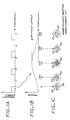
- FIGS. 1A and 1B An exemplary monopulse doppler waveform is illustrated in FIGS. 1A and 1B.
- FIG. 1A illustrates the transmit enable status as a function of time, showing the high duty factor and low PRF of the waveform.
- FIG. 1B shows the power distribution as a function of time for an exemplary one of the transmitted pulses, showing the pulse shaping. It is known that such pulse shaping is desirable in phased array radars in look-down scenarios, since slow moving target detection would be degraded in detection of slow moving targets. Ground clutter from the DC doppler filter will contaminate the lower non-DC filters, unless such pulse shaping is employed. Shaping is also useful in some conventional waveform applications to reduce the long range clutter settling time.
- Transmit pulse shaping must be very precise in order to achieve adequate mainlobe clutter rejection. Also, to minimize array prime power and cooling requirements, it is important that high efficiency (i.e., minimal energy use) be maintained at the tapered edges.
- one method of generating shaped pulses is to continuously vary the transmit power of each active element over the pulse length.
- this method it is extremely difficult to control the element amplitudes with sufficient precision.
- Another method of achieving pulse shaping is duty factor modulation.
- the idea is to form the desired long shaped pulse as a series of many subpulses.
- the center-to-center spacing of the subpulses is constant, but the subpulse widths are reduced away from the long pulse center.
- This technique allows more precise control of the effective amplitude taper.
- the efficiency is poor because the elements as likely to require full power even during the gaps between subpulses.
- an active array system comprising a large number of radiating elements dispersed over the radiating aperture by a transmit pulse shaping circuit which precisely shapes individual pulses.
- the pulse shaping circuit is characterized in that, for a given pulse, the number of radiating elements which are turned on is gradually increased at the beginning of a transmit pulse interval until all elements are turned on at the middle of the pulse interval, and thereafter the number of elements which are turned on is gradually decreased until no elements are turned on at the end of the pulse interval.
- This type of array is described as a "glittering array.”
- the transmitting elements which are turned on from the interval beginning until all elements are on are randomly dispersed over the element array aperture. Moreover, the elements are turned off after the middle of the pulse interval in inverse order to the order in which they were turned on.
- FIG. 1C illustrates a simplified array 20 comprising a small number of discrete elements 22 arranged in a circular aperture.
- a darkened element represents an element which is radiating or "on”
- a non-darkened element represents an element which is not radiating or "off” at that particular instant of time.
- the status of the array elements is shown for five discrete instants of time during a single pulse. Thus, at the beginning of the pulse, at time T1, only a few (two) array elements, spread out over the array, are turned on. At time T2, more elements (five) of the array are turned on.
- Time T3 corresponds to time T2, and the same array elements are turned on as were turned on for time T2.
- time T5 corresponds to time T1 in the particular array elements being turned on.
- the effective amplitude can be controlled with precision because each element is either off or on in saturation.
- high efficiency is maintained with the glittering array, because switching elements off virtually eliminates elemental power consumption. If a variable attenuator was used instead, significant savings in power would not be realized.
- waveform duty factor modification were used, implementation of the timing control circuitry would be difficult and would not result in equivalent savings in power compared to the glittering array.
- the gain as well as the power is proportional to the number of "on" elements, n.
- the effective pulse amplitude, a is also proportional to n.
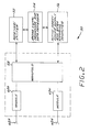
- the system 50 comprises a receiver/exciter 52, a radar signal processor and data processor 54 and an active array power supply and beam steering computer 56.
- the receiver/exciter 52 provides the transmitter signal to an RF manifold, which distributes the transmit signal to the various active modules 60A-60N.
- the modules 60A-60N are in turn connected to the respective radiating elements 62A-62N.
- the modules 60A-60N include variable phase shifter circuits which act in response to commands from the beam steering computer 56 to steer a transmit or receive beam in a desired direction.
- the manifold 58 in turn combines the signals received from the elements 62A-62N and provides the combined received signal to the receiver/exciter 52 for processing by the processor 54.
- the processor 54 and/or the computer 56 further comprises means for turning the transmit modules on and off to obtain the glittering array operation described above.
- the modules may contain the control circuitry. While there are many ways in which such a capability could be obtained, the embodiment of FIG. 2 employs a synchronization pulse generated periodically during a given pulse period and provided to the respective modules. Each module in turn includes a means for counting the successive pulses, which are received periodically, say at one microsecond intervals, and based on the count, turning on only a predetermined set of modules corresponding to the present count value. Each set can be represented by data stored in a memory addressed by the count value.
- an exemplary module 60A is responsive to synchronization pulses received from the computer 56, received at, say, one microsecond intervals.
- the module 60A includes a counter 64 which maintains a count of the number of synchronization pulses received since the initiation of exciter pulse operation.
- the counter state value is compared at comparator 66 to a preset value when the module is to be turned on, and at comparator 68 to a preset value at which the module is to be turned off.
- Turn on circuitry 70 is triggered to turn the module on when the counter state equals the preset value for comparator 66.
- Turn off circuitry 72 is triggered to turn the module off when the counter state equals the preset value for comparator 68.
- Each of the modules has corresponding elements, but the particular preset values for turning on and turning off a particular module will vary, depending on the preselected random distribution of the elements over a particular pulse. After an exciter pulse is terminated, each counter 64 state is reset.
- amplitude tapering in accordance with the invention can be used with conventional waveforms other than monopulse doppler and pulse burst waveforms to reduce the clutter settling time.
- the invention is not limited to use with monopulse doppler and pulse burst waveforms.
Landscapes
- Engineering & Computer Science (AREA)
- Radar, Positioning & Navigation (AREA)
- Remote Sensing (AREA)
- Computer Networks & Wireless Communication (AREA)
- Physics & Mathematics (AREA)
- General Physics & Mathematics (AREA)
- Radar Systems Or Details Thereof (AREA)
Applications Claiming Priority (2)
| Application Number | Priority Date | Filing Date | Title |
|---|---|---|---|
| US07/722,023 US5225841A (en) | 1991-06-27 | 1991-06-27 | Glittering array for radar pulse shaping |
| US722023 | 1991-06-27 |
Publications (3)
| Publication Number | Publication Date |
|---|---|
| EP0520489A2 true EP0520489A2 (fr) | 1992-12-30 |
| EP0520489A3 EP0520489A3 (en) | 1993-06-30 |
| EP0520489B1 EP0520489B1 (fr) | 1998-01-21 |
Family
ID=24900207
Family Applications (1)
| Application Number | Title | Priority Date | Filing Date |
|---|---|---|---|
| EP92110811A Expired - Lifetime EP0520489B1 (fr) | 1991-06-27 | 1992-06-26 | Réseau d'antennes à fluctuation de lobe pour mettre en forme des impulsions de radar |
Country Status (8)
| Country | Link |
|---|---|
| US (1) | US5225841A (fr) |
| EP (1) | EP0520489B1 (fr) |
| JP (1) | JP2564449B2 (fr) |
| KR (1) | KR930000964A (fr) |
| CA (1) | CA2071663C (fr) |
| DE (1) | DE69224109T2 (fr) |
| ES (1) | ES2111017T3 (fr) |
| IL (1) | IL102268A (fr) |
Cited By (5)
| Publication number | Priority date | Publication date | Assignee | Title |
|---|---|---|---|---|
| NL1009033C2 (nl) * | 1998-04-29 | 1999-11-01 | Hollandse Signaalapparaten Bv | Antennesysteem. |
| WO2004021513A1 (fr) * | 2002-08-30 | 2004-03-11 | Telefonaktiebolaget Lm Ericsson | Reduction des quasi-ambiguites |
| WO2004021512A1 (fr) * | 2002-08-30 | 2004-03-11 | Telefonaktiebolaget Lm Ericsson | Procede permettant d'augmenter la precision de mesure d'un reseau d'antennes |
| WO2007040635A1 (fr) * | 2005-09-16 | 2007-04-12 | Northrop Grumman Corporation | Systeme d'antenne reseau amincie ameliore |
| CN109638478A (zh) * | 2017-10-06 | 2019-04-16 | 波音公司 | 用于热管理的有源电子扫描天线的自适应稀疏 |
Families Citing this family (23)
| Publication number | Priority date | Publication date | Assignee | Title |
|---|---|---|---|---|
| US5563609A (en) * | 1994-05-16 | 1996-10-08 | Hughes Electronics | Antenna system with plural beam sequential offset |
| US5537367A (en) * | 1994-10-20 | 1996-07-16 | Lockwood; Geoffrey R. | Sparse array structures |
| US6114986A (en) * | 1998-03-04 | 2000-09-05 | Northrop Grumman Corporation | Dual channel microwave transmit/receive module for an active aperture of a radar system |
| US6034633A (en) * | 1998-03-04 | 2000-03-07 | Northrop Grumman Corporation | Transmit/receive module having multiple transmit/receive paths with shared circuitry |
| WO2000026415A2 (fr) * | 1998-11-02 | 2000-05-11 | The Brigham & Women's Hospital, Inc. | Technique d'hybridation genomique soustractive |
| US6573862B2 (en) | 2000-12-12 | 2003-06-03 | Harris Corporation | Phased array antenna including element control device providing fault detection and related methods |
| US6690324B2 (en) | 2000-12-12 | 2004-02-10 | Harris Corporation | Phased array antenna having reduced beam settling times and related methods |
| US6473037B2 (en) | 2000-12-12 | 2002-10-29 | Harris Corporation | Phased array antenna system having prioritized beam command and data transfer and related methods |
| US6522294B2 (en) | 2000-12-12 | 2003-02-18 | Harris Corporation | Phased array antenna providing rapid beam shaping and related methods |
| US6593881B2 (en) | 2000-12-12 | 2003-07-15 | Harris Corporation | Phased array antenna including an antenna module temperature sensor and related methods |
| US6522293B2 (en) | 2000-12-12 | 2003-02-18 | Harris Corporation | Phased array antenna having efficient compensation data distribution and related methods |
| US6573863B2 (en) | 2000-12-12 | 2003-06-03 | Harris Corporation | Phased array antenna system utilizing highly efficient pipelined processing and related methods |
| US6587077B2 (en) | 2000-12-12 | 2003-07-01 | Harris Corporation | Phased array antenna providing enhanced element controller data communication and related methods |
| US6824307B2 (en) | 2000-12-12 | 2004-11-30 | Harris Corporation | Temperature sensor and related methods |
| US6496143B1 (en) | 2001-11-09 | 2002-12-17 | Harris Corporation | Phased array antenna including a multi-mode element controller and related method |
| US6646600B2 (en) | 2001-11-09 | 2003-11-11 | Harris Corporation | Phased array antenna with controllable amplifier bias adjustment and related methods |
| WO2004082213A1 (fr) * | 2003-03-10 | 2004-09-23 | Buffalo Inc. | Point d'acces |
| US7081851B1 (en) * | 2005-02-10 | 2006-07-25 | Raytheon Company | Overlapping subarray architecture |
| US20070075894A1 (en) * | 2005-10-04 | 2007-04-05 | Lockheed Martin Corporation | RF Pulse Shaping By Incremental Amplifier Turn On and Off |
| US7978123B2 (en) * | 2009-05-04 | 2011-07-12 | Raytheon Company | System and method for operating a radar system in a continuous wave mode for data communication |
| WO2013020105A2 (fr) * | 2011-08-04 | 2013-02-07 | Rambus Inc. | Système de suivi de bas coût |
| US10254164B2 (en) * | 2015-04-16 | 2019-04-09 | Nanommics, Inc. | Compact mapping spectrometer |
| US10324166B2 (en) * | 2015-09-28 | 2019-06-18 | Rockwell Collins, Inc. | Affordable combined pulsed/FMCW radar AESA |
Family Cites Families (6)
| Publication number | Priority date | Publication date | Assignee | Title |
|---|---|---|---|---|
| US3267472A (en) * | 1960-07-20 | 1966-08-16 | Litton Systems Inc | Variable aperture antenna system |
| US4050074A (en) * | 1976-07-16 | 1977-09-20 | Tull Aviation Corporation | Blended step scan beam signal from fixed beam components |
| US4124852A (en) * | 1977-01-24 | 1978-11-07 | Raytheon Company | Phased power switching system for scanning antenna array |
| US4129870A (en) * | 1977-09-30 | 1978-12-12 | Tull Aviation Corporation | Apparatus for synthesis of scanning beam |
| US4451831A (en) * | 1981-06-29 | 1984-05-29 | Sperry Corporation | Circular array scanning network |
| USH548H (en) * | 1987-12-07 | 1988-11-01 | The United States Of America As Represented By The Secretary Of The Army | Group orthogonal arrays for elimination of multiple-time-around echos in radars |
-
1991
- 1991-06-27 US US07/722,023 patent/US5225841A/en not_active Expired - Fee Related
-
1992
- 1992-06-19 CA CA002071663A patent/CA2071663C/fr not_active Expired - Fee Related
- 1992-06-21 IL IL10226892A patent/IL102268A/en not_active IP Right Cessation
- 1992-06-26 DE DE69224109T patent/DE69224109T2/de not_active Expired - Fee Related
- 1992-06-26 ES ES92110811T patent/ES2111017T3/es not_active Expired - Lifetime
- 1992-06-26 EP EP92110811A patent/EP0520489B1/fr not_active Expired - Lifetime
- 1992-06-26 KR KR1019920011285A patent/KR930000964A/ko not_active Ceased
- 1992-06-29 JP JP4171238A patent/JP2564449B2/ja not_active Expired - Fee Related
Cited By (10)
| Publication number | Priority date | Publication date | Assignee | Title |
|---|---|---|---|---|
| NL1009033C2 (nl) * | 1998-04-29 | 1999-11-01 | Hollandse Signaalapparaten Bv | Antennesysteem. |
| EP0954056A1 (fr) * | 1998-04-29 | 1999-11-03 | Hollandse Signaalapparaten B.V. | Système d'antenne |
| US6140962A (en) * | 1998-04-29 | 2000-10-31 | Hollandse Signaalapparaten B.V. | Antenna system |
| AU746829B2 (en) * | 1998-04-29 | 2002-05-02 | Thales Nederland B.V. | Antenna system |
| WO2004021513A1 (fr) * | 2002-08-30 | 2004-03-11 | Telefonaktiebolaget Lm Ericsson | Reduction des quasi-ambiguites |
| WO2004021512A1 (fr) * | 2002-08-30 | 2004-03-11 | Telefonaktiebolaget Lm Ericsson | Procede permettant d'augmenter la precision de mesure d'un reseau d'antennes |
| US7372402B2 (en) | 2002-08-30 | 2008-05-13 | Telfonaktiebolaget Lm Ericsson (Publ) | Method for enhancing the measuring accuracy in an antenna array |
| WO2007040635A1 (fr) * | 2005-09-16 | 2007-04-12 | Northrop Grumman Corporation | Systeme d'antenne reseau amincie ameliore |
| CN109638478A (zh) * | 2017-10-06 | 2019-04-16 | 波音公司 | 用于热管理的有源电子扫描天线的自适应稀疏 |
| CN109638478B (zh) * | 2017-10-06 | 2022-06-07 | 波音公司 | 用于自适应地控制有源相控阵天线的方法和装置 |
Also Published As
| Publication number | Publication date |
|---|---|
| KR930000964A (ko) | 1993-01-16 |
| JP2564449B2 (ja) | 1996-12-18 |
| EP0520489A3 (en) | 1993-06-30 |
| EP0520489B1 (fr) | 1998-01-21 |
| IL102268A (en) | 1995-08-31 |
| DE69224109D1 (de) | 1998-02-26 |
| CA2071663C (fr) | 1995-03-28 |
| JPH05188132A (ja) | 1993-07-30 |
| DE69224109T2 (de) | 1998-08-20 |
| ES2111017T3 (es) | 1998-03-01 |
| CA2071663A1 (fr) | 1992-12-28 |
| US5225841A (en) | 1993-07-06 |
Similar Documents
| Publication | Publication Date | Title |
|---|---|---|
| US5225841A (en) | Glittering array for radar pulse shaping | |
| US5369409A (en) | Time-sharing FM radar system | |
| US5146616A (en) | Ultra wideband radar transmitter employing synthesized short pulses | |
| US5982329A (en) | Single channel transceiver with polarization diversity | |
| US6225943B1 (en) | Method of operating pulse radar | |
| EP0611969A1 (fr) | Système de radar à temps partagé | |
| US6140962A (en) | Antenna system | |
| US5013979A (en) | Phased frequency steered antenna array | |
| DE69902064T2 (de) | Fahrzeug-Radargerät zum Verwalten von Informationen über Reflektoren | |
| EP0780700A2 (fr) | Procédé et appareil de fonctionnement d'un radar de surveillance pour aéroport employant transmissions d'impulsions agiles en fréquence | |
| US20050046607A1 (en) | Ultra high resolution radar with active electronically scanned antenna (AESA) | |
| EP0320306A2 (fr) | Radar à réseau d'antennes commandées en phase | |
| EP0614092B1 (fr) | Appareil radar | |
| EP0132378B1 (fr) | Dispositif radar à balayage avec faisceaux multiples | |
| US3344426A (en) | Radar system | |
| AU635878B2 (en) | An active phased array radar system | |
| CN119199760B (zh) | 一种多波束接收窄波束发射的相控阵雷达干扰机系统 | |
| GB2134741A (en) | Radar apparatus | |
| CA2170646A1 (fr) | Radar | |
| US4532520A (en) | Target detection systems | |
| US4435710A (en) | System for obscuring antenna sidelobe signals | |
| JPH05107335A (ja) | アクテイブフエーズドアレイレーダ空中線装置 | |
| WO1986007467A1 (fr) | Radar de surveillance a faisceaux multiples | |
| US3721980A (en) | Gated range search radar | |
| Milne | The combination of pulse compression with frequency scanning for three-dimensional radars |
Legal Events
| Date | Code | Title | Description |
|---|---|---|---|
| PUAI | Public reference made under article 153(3) epc to a published international application that has entered the european phase |
Free format text: ORIGINAL CODE: 0009012 |
|
| AK | Designated contracting states |
Kind code of ref document: A2 Designated state(s): CH DE ES FR GB IT LI SE |
|
| PUAL | Search report despatched |
Free format text: ORIGINAL CODE: 0009013 |
|
| AK | Designated contracting states |
Kind code of ref document: A3 Designated state(s): CH DE ES FR GB IT LI SE |
|
| 17P | Request for examination filed |
Effective date: 19931211 |
|
| 17Q | First examination report despatched |
Effective date: 19950907 |
|
| GRAG | Despatch of communication of intention to grant |
Free format text: ORIGINAL CODE: EPIDOS AGRA |
|
| GRAG | Despatch of communication of intention to grant |
Free format text: ORIGINAL CODE: EPIDOS AGRA |
|
| GRAH | Despatch of communication of intention to grant a patent |
Free format text: ORIGINAL CODE: EPIDOS IGRA |
|
| GRAH | Despatch of communication of intention to grant a patent |
Free format text: ORIGINAL CODE: EPIDOS IGRA |
|
| GRAA | (expected) grant |
Free format text: ORIGINAL CODE: 0009210 |
|
| AK | Designated contracting states |
Kind code of ref document: B1 Designated state(s): CH DE ES FR GB IT LI SE |
|
| REG | Reference to a national code |
Ref country code: CH Ref legal event code: EP |
|
| ITF | It: translation for a ep patent filed | ||
| REF | Corresponds to: |
Ref document number: 69224109 Country of ref document: DE Date of ref document: 19980226 |
|
| REG | Reference to a national code |
Ref country code: ES Ref legal event code: FG2A Ref document number: 2111017 Country of ref document: ES Kind code of ref document: T3 |
|
| ET | Fr: translation filed | ||
| REG | Reference to a national code |
Ref country code: CH Ref legal event code: NV Representative=s name: ISLER & PEDRAZZINI AG |
|
| PLBE | No opposition filed within time limit |
Free format text: ORIGINAL CODE: 0009261 |
|
| STAA | Information on the status of an ep patent application or granted ep patent |
Free format text: STATUS: NO OPPOSITION FILED WITHIN TIME LIMIT |
|
| 26N | No opposition filed | ||
| REG | Reference to a national code |
Ref country code: GB Ref legal event code: 732E |
|
| REG | Reference to a national code |
Ref country code: ES Ref legal event code: PC2A |
|
| REG | Reference to a national code |
Ref country code: FR Ref legal event code: TP Ref country code: FR Ref legal event code: CD Ref country code: FR Ref legal event code: CA |
|
| REG | Reference to a national code |
Ref country code: GB Ref legal event code: IF02 |
|
| PGFP | Annual fee paid to national office [announced via postgrant information from national office to epo] |
Ref country code: FR Payment date: 20040513 Year of fee payment: 13 |
|
| PGFP | Annual fee paid to national office [announced via postgrant information from national office to epo] |
Ref country code: GB Payment date: 20040517 Year of fee payment: 13 |
|
| PGFP | Annual fee paid to national office [announced via postgrant information from national office to epo] |
Ref country code: CH Payment date: 20040519 Year of fee payment: 13 |
|
| PGFP | Annual fee paid to national office [announced via postgrant information from national office to epo] |
Ref country code: DE Payment date: 20040520 Year of fee payment: 13 |
|
| PGFP | Annual fee paid to national office [announced via postgrant information from national office to epo] |
Ref country code: SE Payment date: 20040521 Year of fee payment: 13 |
|
| PGFP | Annual fee paid to national office [announced via postgrant information from national office to epo] |
Ref country code: ES Payment date: 20040607 Year of fee payment: 13 |
|
| PG25 | Lapsed in a contracting state [announced via postgrant information from national office to epo] |
Ref country code: IT Free format text: LAPSE BECAUSE OF NON-PAYMENT OF DUE FEES;WARNING: LAPSES OF ITALIAN PATENTS WITH EFFECTIVE DATE BEFORE 2007 MAY HAVE OCCURRED AT ANY TIME BEFORE 2007. THE CORRECT EFFECTIVE DATE MAY BE DIFFERENT FROM THE ONE RECORDED. Effective date: 20050626 Ref country code: GB Free format text: LAPSE BECAUSE OF NON-PAYMENT OF DUE FEES Effective date: 20050626 |
|
| PG25 | Lapsed in a contracting state [announced via postgrant information from national office to epo] |
Ref country code: SE Free format text: LAPSE BECAUSE OF NON-PAYMENT OF DUE FEES Effective date: 20050627 Ref country code: ES Free format text: LAPSE BECAUSE OF NON-PAYMENT OF DUE FEES Effective date: 20050627 |
|
| PG25 | Lapsed in a contracting state [announced via postgrant information from national office to epo] |
Ref country code: LI Free format text: LAPSE BECAUSE OF NON-PAYMENT OF DUE FEES Effective date: 20050630 Ref country code: CH Free format text: LAPSE BECAUSE OF NON-PAYMENT OF DUE FEES Effective date: 20050630 |
|
| PG25 | Lapsed in a contracting state [announced via postgrant information from national office to epo] |
Ref country code: DE Free format text: LAPSE BECAUSE OF NON-PAYMENT OF DUE FEES Effective date: 20060103 |
|
| REG | Reference to a national code |
Ref country code: CH Ref legal event code: PL |
|
| EUG | Se: european patent has lapsed | ||
| PG25 | Lapsed in a contracting state [announced via postgrant information from national office to epo] |
Ref country code: FR Free format text: LAPSE BECAUSE OF NON-PAYMENT OF DUE FEES Effective date: 20060228 |
|
| GBPC | Gb: european patent ceased through non-payment of renewal fee |
Effective date: 20050626 |
|
| REG | Reference to a national code |
Ref country code: FR Ref legal event code: ST Effective date: 20060228 |
|
| REG | Reference to a national code |
Ref country code: ES Ref legal event code: FD2A Effective date: 20050627 |