EP0520536A1 - Piston assemblé refroidi par huile pour moteur Diesel - Google Patents
Piston assemblé refroidi par huile pour moteur Diesel Download PDFInfo
- Publication number
- EP0520536A1 EP0520536A1 EP92201603A EP92201603A EP0520536A1 EP 0520536 A1 EP0520536 A1 EP 0520536A1 EP 92201603 A EP92201603 A EP 92201603A EP 92201603 A EP92201603 A EP 92201603A EP 0520536 A1 EP0520536 A1 EP 0520536A1
- Authority
- EP
- European Patent Office
- Prior art keywords
- piston
- cooling
- piston crown
- plane
- diesel engines
- Prior art date
- Legal status (The legal status is an assumption and is not a legal conclusion. Google has not performed a legal analysis and makes no representation as to the accuracy of the status listed.)
- Granted
Links
Images
Classifications
-
- F—MECHANICAL ENGINEERING; LIGHTING; HEATING; WEAPONS; BLASTING
- F02—COMBUSTION ENGINES; HOT-GAS OR COMBUSTION-PRODUCT ENGINE PLANTS
- F02B—INTERNAL-COMBUSTION PISTON ENGINES; COMBUSTION ENGINES IN GENERAL
- F02B23/00—Other engines characterised by special shape or construction of combustion chambers to improve operation
- F02B23/02—Other engines characterised by special shape or construction of combustion chambers to improve operation with compression ignition
- F02B23/06—Other engines characterised by special shape or construction of combustion chambers to improve operation with compression ignition the combustion space being arranged in working piston
- F02B23/0696—W-piston bowl, i.e. the combustion space having a central projection pointing towards the cylinder head and the surrounding wall being inclined towards the cylinder wall
-
- F—MECHANICAL ENGINEERING; LIGHTING; HEATING; WEAPONS; BLASTING
- F02—COMBUSTION ENGINES; HOT-GAS OR COMBUSTION-PRODUCT ENGINE PLANTS
- F02F—CYLINDERS, PISTONS OR CASINGS, FOR COMBUSTION ENGINES; ARRANGEMENTS OF SEALINGS IN COMBUSTION ENGINES
- F02F3/00—Pistons
- F02F3/16—Pistons having cooling means
- F02F3/20—Pistons having cooling means the means being a fluid flowing through or along piston
- F02F3/22—Pistons having cooling means the means being a fluid flowing through or along piston the fluid being liquid
- F02F3/225—Pistons having cooling means the means being a fluid flowing through or along piston the fluid being liquid the liquid being directed into blind holes
-
- F—MECHANICAL ENGINEERING; LIGHTING; HEATING; WEAPONS; BLASTING
- F02—COMBUSTION ENGINES; HOT-GAS OR COMBUSTION-PRODUCT ENGINE PLANTS
- F02B—INTERNAL-COMBUSTION PISTON ENGINES; COMBUSTION ENGINES IN GENERAL
- F02B3/00—Engines characterised by air compression and subsequent fuel addition
- F02B3/06—Engines characterised by air compression and subsequent fuel addition with compression ignition
-
- F—MECHANICAL ENGINEERING; LIGHTING; HEATING; WEAPONS; BLASTING
- F02—COMBUSTION ENGINES; HOT-GAS OR COMBUSTION-PRODUCT ENGINE PLANTS
- F02F—CYLINDERS, PISTONS OR CASINGS, FOR COMBUSTION ENGINES; ARRANGEMENTS OF SEALINGS IN COMBUSTION ENGINES
- F02F2200/00—Manufacturing
- F02F2200/04—Forging of engine parts
-
- F—MECHANICAL ENGINEERING; LIGHTING; HEATING; WEAPONS; BLASTING
- F05—INDEXING SCHEMES RELATING TO ENGINES OR PUMPS IN VARIOUS SUBCLASSES OF CLASSES F01-F04
- F05C—INDEXING SCHEME RELATING TO MATERIALS, MATERIAL PROPERTIES OR MATERIAL CHARACTERISTICS FOR MACHINES, ENGINES OR PUMPS OTHER THAN NON-POSITIVE-DISPLACEMENT MACHINES OR ENGINES
- F05C2201/00—Metals
- F05C2201/02—Light metals
- F05C2201/021—Aluminium
-
- F—MECHANICAL ENGINEERING; LIGHTING; HEATING; WEAPONS; BLASTING
- F05—INDEXING SCHEMES RELATING TO ENGINES OR PUMPS IN VARIOUS SUBCLASSES OF CLASSES F01-F04
- F05C—INDEXING SCHEME RELATING TO MATERIALS, MATERIAL PROPERTIES OR MATERIAL CHARACTERISTICS FOR MACHINES, ENGINES OR PUMPS OTHER THAN NON-POSITIVE-DISPLACEMENT MACHINES OR ENGINES
- F05C2201/00—Metals
- F05C2201/04—Heavy metals
- F05C2201/0433—Iron group; Ferrous alloys, e.g. steel
- F05C2201/0448—Steel
-
- Y—GENERAL TAGGING OF NEW TECHNOLOGICAL DEVELOPMENTS; GENERAL TAGGING OF CROSS-SECTIONAL TECHNOLOGIES SPANNING OVER SEVERAL SECTIONS OF THE IPC; TECHNICAL SUBJECTS COVERED BY FORMER USPC CROSS-REFERENCE ART COLLECTIONS [XRACs] AND DIGESTS
- Y02—TECHNOLOGIES OR APPLICATIONS FOR MITIGATION OR ADAPTATION AGAINST CLIMATE CHANGE
- Y02T—CLIMATE CHANGE MITIGATION TECHNOLOGIES RELATED TO TRANSPORTATION
- Y02T10/00—Road transport of goods or passengers
- Y02T10/10—Internal combustion engine [ICE] based vehicles
- Y02T10/12—Improving ICE efficiencies
Definitions
- the invention relates to a built, oil-cooled piston for diesel engines, in particular for medium-speed diesel engines with a high charge, consisting of a piston body receiving the piston pin and a piston crown supporting the ring section and the top land, which are supported on one another via bearing surfaces located in their plane of separation and by corresponding bores inserted screws are clamped against each other, with a central cooling chamber provided with an opening on the crankcase side between the piston body and piston crown.
- the piston body and piston crown are supported on one another via annular support surfaces arranged on concentric support collars, and the support collars form the outer boundary of the central cooling space and the radial inner boundary of a cooling channel running behind the ring section.
- oil cooling of a defined part of the piston is no longer sufficient. Rather, cavities are required that cover all areas of the piston crown, the ring section and the top land that are subject to high thermal stress.
- built, oil-cooled pistons of the constructions described above are known, in which the base consists of steel or high-quality cast iron and the piston body consists of aluminum-silicon piston alloy or spheroidal graphite cast iron.
- the cooling oil is supplied to the cooling chamber via corresponding openings in the piston skirt either via connecting rods and piston pins or via a spray nozzle attached to the crankcase.
- the cooling oil can also be supplied in the opposite direction directly to the cooling chamber via a spray nozzle attached to the small connecting rod eye.
- a spray nozzle attached to the small connecting rod eye.
- the solution to this problem consists in one from the central cooling space or from the cooling channel running behind the ring section to the area behind the top land and the Annular space running around the piston crown, the central plane of which is inclined with respect to the plane of separation of the piston components and in the section on the cooling chamber side several spacers are firmly inserted.
- the plane of the annular space is inclined by 20 to 90 °, preferably 30 to 80 °, with respect to the plane of separation of the piston components.
- the surface overflowed by the pendulum effect of the cooling oil is increased comparatively by up to 60%, so that the amount of heat dissipated per unit of time from the combustion chamber-side wall of the annular space is comparatively considerably larger, with the result that the temperature can be kept significantly lower in the area at risk from excessive temperatures. Coking of the cooling oil and thus the formation of a heat-insulating coke layer at the bottom of the annular space is avoided as a result of the measure according to the invention.
- the annular space can be produced with relatively little effort by turning compared to the production of the blind holes by drilling.
- the piston weight is reduced by up to 5%.
- the section of the annular space closest to the piston crown edge has a surface area which is up to 60% larger than that of the section on the cooling chamber side or cooling duct side.
- the spacers inserted into the section of the annular space on the cooling space side or cooling channel side which are intended to prevent deformation of the ring area, are soldered, welded or screwed into corresponding bores.
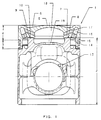
- the built, oil-cooled piston (1) for medium-speed diesel engines with a high charge consists of the lower part (2) made of cast iron, which does not show the piston pin, and the forged steel part that supports the ring section (3) and the top land (4) with a flat combustion chamber bowl (6).
- the lower part (2) and the piston crown (5) are braced against each other by means of expansion screws (12) guided from the piston foot through corresponding threaded bores (11).
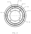
- the cooling oil is supplied via the connecting rod (not shown) and the piston pin and the cooling oil feed bores (13) to the annular cooling channel (14), which runs behind the ring section (3) and is radially inwardly delimited by the support collar (10), from which a cooling chamber ( 15) extends behind the top land and the piston crown edge, the central plane of which is inclined by 75 ° with respect to the separation plane.
- Spacers (16) are soldered into the cooling chamber (15) in the section facing the cooling channel (14).
- the section of the cooling chamber (15) closest to the piston crown is enlarged in such a way that there is a uniform wall thickness between the cooling chamber and the piston crown, between the cooling chamber and the combustion chamber trough and between the cooling chamber and the top land.
- the annular cooling space (15) is in the support collar (7) of the Piston base overflow bores (17) for the cooling oil connected to the central cooling chamber (18), from which the cooling oil can exit into the crank chamber via the opening (19).
- the overflow bores (17) in the support collar (7) of the lower part (2).
Landscapes
- Engineering & Computer Science (AREA)
- Chemical & Material Sciences (AREA)
- Combustion & Propulsion (AREA)
- Mechanical Engineering (AREA)
- General Engineering & Computer Science (AREA)
- Physics & Mathematics (AREA)
- Fluid Mechanics (AREA)
- Pistons, Piston Rings, And Cylinders (AREA)
- Lubrication Of Internal Combustion Engines (AREA)
Applications Claiming Priority (2)
| Application Number | Priority Date | Filing Date | Title |
|---|---|---|---|
| DE4120850A DE4120850A1 (de) | 1991-06-25 | 1991-06-25 | Gebauter, oelgekuehlter kolben fuer dieselmotoren |
| DE4120850 | 1991-06-25 |
Publications (2)
| Publication Number | Publication Date |
|---|---|
| EP0520536A1 true EP0520536A1 (fr) | 1992-12-30 |
| EP0520536B1 EP0520536B1 (fr) | 1997-04-09 |
Family
ID=6434648
Family Applications (1)
| Application Number | Title | Priority Date | Filing Date |
|---|---|---|---|
| EP92201603A Expired - Lifetime EP0520536B1 (fr) | 1991-06-25 | 1992-06-04 | Piston assemblé refroidi par huile pour moteur Diesel |
Country Status (3)
| Country | Link |
|---|---|
| EP (1) | EP0520536B1 (fr) |
| AT (1) | ATE151501T1 (fr) |
| DE (2) | DE4120850A1 (fr) |
Cited By (5)
| Publication number | Priority date | Publication date | Assignee | Title |
|---|---|---|---|---|
| US6494170B2 (en) | 2000-12-01 | 2002-12-17 | Caterpillar Inc | Two-piece piston assembly with skirt having pin bore oil ducts |
| DE10244512A1 (de) * | 2002-09-25 | 2004-04-15 | Mahle Gmbh | Mehrteiliger gekühlter Kolben für einen Verbrennungsmotor |
| US10227949B2 (en) | 2016-12-23 | 2019-03-12 | Caterpillar Inc. | Piston for an internal combustion engine and method for producing said piston |
| US10294887B2 (en) | 2015-11-18 | 2019-05-21 | Tenneco Inc. | Piston providing for reduced heat loss using cooling media |
| WO2021122967A1 (fr) | 2019-12-19 | 2021-06-24 | Ks Kolbenschmidt Gmbh | Piston refroidi à l'huile pour moteurs à combustion interne |
Families Citing this family (1)
| Publication number | Priority date | Publication date | Assignee | Title |
|---|---|---|---|---|
| DE10244510A1 (de) * | 2002-09-25 | 2004-04-08 | Mahle Gmbh | Einteiliger Kühlkanalkolben für einen Verbrennungsmotor |
Citations (4)
| Publication number | Priority date | Publication date | Assignee | Title |
|---|---|---|---|---|
| FR954188A (fr) * | 1947-10-02 | 1949-12-20 | Oerlikon Buehrle Ag | Piston en métal léger pour moteurs à combustion interne |
| FR1301299A (fr) * | 1961-06-20 | 1962-08-17 | Alsacienne Constr Meca | Dispositif de refroidissement pour pistons de moteurs thermiques |
| FR2582351A1 (fr) * | 1985-05-24 | 1986-11-28 | Man B & W Diesel Gmbh | Piston en plusieurs pieces, a refroidissement par l'huile, pour moteurs a combustion interne |
| EP0403767A2 (fr) * | 1989-06-19 | 1990-12-27 | Mahle GmbH | Piston pour moteurs à combustion interne avec un courant d'huile de refroidissement dans la tête de piston |
Family Cites Families (2)
| Publication number | Priority date | Publication date | Assignee | Title |
|---|---|---|---|---|
| DE3502644A1 (de) * | 1985-01-26 | 1986-07-31 | M.A.N.-B & W Diesel GmbH, 8900 Augsburg | Oelgekuehlter, mehrteiliger tauchkolben fuer hubkolbenbrennkraftmaschinen |
| DE3709969A1 (de) * | 1987-03-26 | 1988-10-06 | Kolbenschmidt Ag | Kolben mit fluessigkeitskuehlung |
-
1991
- 1991-06-25 DE DE4120850A patent/DE4120850A1/de not_active Withdrawn
-
1992
- 1992-06-04 AT AT92201603T patent/ATE151501T1/de not_active IP Right Cessation
- 1992-06-04 EP EP92201603A patent/EP0520536B1/fr not_active Expired - Lifetime
- 1992-06-04 DE DE59208313T patent/DE59208313D1/de not_active Expired - Fee Related
Patent Citations (4)
| Publication number | Priority date | Publication date | Assignee | Title |
|---|---|---|---|---|
| FR954188A (fr) * | 1947-10-02 | 1949-12-20 | Oerlikon Buehrle Ag | Piston en métal léger pour moteurs à combustion interne |
| FR1301299A (fr) * | 1961-06-20 | 1962-08-17 | Alsacienne Constr Meca | Dispositif de refroidissement pour pistons de moteurs thermiques |
| FR2582351A1 (fr) * | 1985-05-24 | 1986-11-28 | Man B & W Diesel Gmbh | Piston en plusieurs pieces, a refroidissement par l'huile, pour moteurs a combustion interne |
| EP0403767A2 (fr) * | 1989-06-19 | 1990-12-27 | Mahle GmbH | Piston pour moteurs à combustion interne avec un courant d'huile de refroidissement dans la tête de piston |
Cited By (5)
| Publication number | Priority date | Publication date | Assignee | Title |
|---|---|---|---|---|
| US6494170B2 (en) | 2000-12-01 | 2002-12-17 | Caterpillar Inc | Two-piece piston assembly with skirt having pin bore oil ducts |
| DE10244512A1 (de) * | 2002-09-25 | 2004-04-15 | Mahle Gmbh | Mehrteiliger gekühlter Kolben für einen Verbrennungsmotor |
| US10294887B2 (en) | 2015-11-18 | 2019-05-21 | Tenneco Inc. | Piston providing for reduced heat loss using cooling media |
| US10227949B2 (en) | 2016-12-23 | 2019-03-12 | Caterpillar Inc. | Piston for an internal combustion engine and method for producing said piston |
| WO2021122967A1 (fr) | 2019-12-19 | 2021-06-24 | Ks Kolbenschmidt Gmbh | Piston refroidi à l'huile pour moteurs à combustion interne |
Also Published As
| Publication number | Publication date |
|---|---|
| DE4120850A1 (de) | 1993-01-07 |
| DE59208313D1 (de) | 1997-05-15 |
| EP0520536B1 (fr) | 1997-04-09 |
| ATE151501T1 (de) | 1997-04-15 |
Similar Documents
| Publication | Publication Date | Title |
|---|---|---|
| EP0464626B1 (fr) | Piston assemblé refroidi par huile pour moteur diesel | |
| DE2625191C2 (de) | Einstückiger Kolben für Brennkraftmaschinen | |
| DE4112889C2 (de) | Verfahren zur Herstellung eines Kolbenkopfes mit Kühlung für einen mehrteiligen, gegliederten Kolben für Verbrennungsmotore, sowie danach hergestellter Kolbenkopf | |
| EP0019323A1 (fr) | Piston pour moteurs à combustion interne | |
| DE3885765T2 (de) | Brennkraftmaschine mit einem kolben, versehen mit einer hoch angeordneten ringnut. | |
| DE3008330A1 (de) | Fluessigkeitsgekuehlter kolben fuer brennkraftmaschinen | |
| DE2543478A1 (de) | Kolben fuer brennkraftmaschinen, insb. dieselmotoren | |
| EP0000592B1 (fr) | Piston refroidi pour moteur à combustion interne et méthode pour sa fabrication | |
| DE102011115826A1 (de) | Kolben für einen Verbrennungsmotor | |
| DE2253961A1 (de) | Kolbenbaugruppe | |
| EP0007661B1 (fr) | Assemblage de piston de moteur à combustion interne comportant des moyens de refroidissement liquide | |
| DE3403624A1 (de) | Gebauter, fluessigkeitsgekuehlter kolben fuer brennkraftmaschinen | |
| DE4014705C2 (de) | Gekühlter Tauchkolben für Verbrennungsmotoren mit voneinander getrenntem Kolbenoberteil und Kolbenschaft | |
| EP0154939B1 (fr) | Piston en deux parties, refroidi à l'huile | |
| CH653099A5 (de) | Kolben fuer eine brennkraftmaschine. | |
| WO2010142389A1 (fr) | Piston en métal léger à bol de combustion multi-cavité | |
| EP0520536B1 (fr) | Piston assemblé refroidi par huile pour moteur Diesel | |
| WO2013075701A1 (fr) | Piston pour moteur à combustion interne et procédé de fabrication correspondant | |
| DE3802714A1 (de) | Zweiteiliger kolben fuer brennkraftmaschinen | |
| DE3017787C2 (de) | Mehrteiliger Kolben für Brennkraftmaschinen | |
| DE3110292A1 (de) | "kolben fuer verbrennungsmotor" | |
| EP3615784B1 (fr) | Piston monobloc coulé destiné à un moteur à combustion interne | |
| DE2923330C2 (de) | Kolben aus legiertem perlitischem sphärolithischem Gußeisen für Brennkraftmaschinen | |
| DE1476049A1 (de) | Kolben | |
| DE19733814C2 (de) | Motorkolben |
Legal Events
| Date | Code | Title | Description |
|---|---|---|---|
| PUAI | Public reference made under article 153(3) epc to a published international application that has entered the european phase |
Free format text: ORIGINAL CODE: 0009012 |
|
| AK | Designated contracting states |
Kind code of ref document: A1 Designated state(s): AT BE CH DE DK ES FR GB GR IT LI LU NL PT SE |
|
| 17P | Request for examination filed |
Effective date: 19930612 |
|
| 17Q | First examination report despatched |
Effective date: 19940722 |
|
| GRAG | Despatch of communication of intention to grant |
Free format text: ORIGINAL CODE: EPIDOS AGRA |
|
| GRAH | Despatch of communication of intention to grant a patent |
Free format text: ORIGINAL CODE: EPIDOS IGRA |
|
| GRAH | Despatch of communication of intention to grant a patent |
Free format text: ORIGINAL CODE: EPIDOS IGRA |
|
| GRAA | (expected) grant |
Free format text: ORIGINAL CODE: 0009210 |
|
| AK | Designated contracting states |
Kind code of ref document: B1 Designated state(s): AT BE CH DE DK ES FR GB GR IT LI LU NL PT SE |
|
| PG25 | Lapsed in a contracting state [announced via postgrant information from national office to epo] |
Ref country code: GR Free format text: LAPSE BECAUSE OF FAILURE TO SUBMIT A TRANSLATION OF THE DESCRIPTION OR TO PAY THE FEE WITHIN THE PRESCRIBED TIME-LIMIT Effective date: 19970409 Ref country code: ES Free format text: THE PATENT HAS BEEN ANNULLED BY A DECISION OF A NATIONAL AUTHORITY Effective date: 19970409 Ref country code: DK Effective date: 19970409 |
|
| REF | Corresponds to: |
Ref document number: 151501 Country of ref document: AT Date of ref document: 19970415 Kind code of ref document: T |
|
| REG | Reference to a national code |
Ref country code: CH Ref legal event code: NV Representative=s name: TROESCH SCHEIDEGGER WERNER AG Ref country code: CH Ref legal event code: EP |
|
| ITF | It: translation for a ep patent filed | ||
| GBT | Gb: translation of ep patent filed (gb section 77(6)(a)/1977) |
Effective date: 19970410 |
|
| REF | Corresponds to: |
Ref document number: 59208313 Country of ref document: DE Date of ref document: 19970515 |
|
| ET | Fr: translation filed | ||
| PG25 | Lapsed in a contracting state [announced via postgrant information from national office to epo] |
Ref country code: LU Free format text: LAPSE BECAUSE OF NON-PAYMENT OF DUE FEES Effective date: 19970604 Ref country code: AT Free format text: LAPSE BECAUSE OF NON-PAYMENT OF DUE FEES Effective date: 19970604 |
|
| PG25 | Lapsed in a contracting state [announced via postgrant information from national office to epo] |
Ref country code: BE Effective date: 19970630 |
|
| PG25 | Lapsed in a contracting state [announced via postgrant information from national office to epo] |
Ref country code: PT Effective date: 19970709 |
|
| BERE | Be: lapsed |
Owner name: KOLBENSCHMIDT A.G. Effective date: 19970630 |
|
| PLBE | No opposition filed within time limit |
Free format text: ORIGINAL CODE: 0009261 |
|
| STAA | Information on the status of an ep patent application or granted ep patent |
Free format text: STATUS: NO OPPOSITION FILED WITHIN TIME LIMIT |
|
| 26N | No opposition filed | ||
| REG | Reference to a national code |
Ref country code: GB Ref legal event code: IF02 |
|
| PGFP | Annual fee paid to national office [announced via postgrant information from national office to epo] |
Ref country code: CH Payment date: 20030520 Year of fee payment: 12 |
|
| PGFP | Annual fee paid to national office [announced via postgrant information from national office to epo] |
Ref country code: NL Payment date: 20030530 Year of fee payment: 12 |
|
| PGFP | Annual fee paid to national office [announced via postgrant information from national office to epo] |
Ref country code: SE Payment date: 20030604 Year of fee payment: 12 |
|
| PG25 | Lapsed in a contracting state [announced via postgrant information from national office to epo] |
Ref country code: SE Free format text: LAPSE BECAUSE OF NON-PAYMENT OF DUE FEES Effective date: 20040605 |
|
| PG25 | Lapsed in a contracting state [announced via postgrant information from national office to epo] |
Ref country code: LI Free format text: LAPSE BECAUSE OF NON-PAYMENT OF DUE FEES Effective date: 20040630 Ref country code: CH Free format text: LAPSE BECAUSE OF NON-PAYMENT OF DUE FEES Effective date: 20040630 |
|
| PG25 | Lapsed in a contracting state [announced via postgrant information from national office to epo] |
Ref country code: NL Free format text: LAPSE BECAUSE OF NON-PAYMENT OF DUE FEES Effective date: 20050101 |
|
| EUG | Se: european patent has lapsed | ||
| EUG | Se: european patent has lapsed | ||
| REG | Reference to a national code |
Ref country code: CH Ref legal event code: PL |
|
| NLV4 | Nl: lapsed or anulled due to non-payment of the annual fee |
Effective date: 20050101 |
|
| PGFP | Annual fee paid to national office [announced via postgrant information from national office to epo] |
Ref country code: GB Payment date: 20060615 Year of fee payment: 15 |
|
| PGFP | Annual fee paid to national office [announced via postgrant information from national office to epo] |
Ref country code: FR Payment date: 20060619 Year of fee payment: 15 |
|
| GBPC | Gb: european patent ceased through non-payment of renewal fee |
Effective date: 20070604 |
|
| REG | Reference to a national code |
Ref country code: FR Ref legal event code: ST Effective date: 20080229 |
|
| PG25 | Lapsed in a contracting state [announced via postgrant information from national office to epo] |
Ref country code: GB Free format text: LAPSE BECAUSE OF NON-PAYMENT OF DUE FEES Effective date: 20070604 |
|
| PG25 | Lapsed in a contracting state [announced via postgrant information from national office to epo] |
Ref country code: FR Free format text: LAPSE BECAUSE OF NON-PAYMENT OF DUE FEES Effective date: 20070702 |
|
| PGFP | Annual fee paid to national office [announced via postgrant information from national office to epo] |
Ref country code: IT Payment date: 20080623 Year of fee payment: 17 |
|
| PGFP | Annual fee paid to national office [announced via postgrant information from national office to epo] |
Ref country code: DE Payment date: 20080620 Year of fee payment: 17 |
|
| PG25 | Lapsed in a contracting state [announced via postgrant information from national office to epo] |
Ref country code: DE Free format text: LAPSE BECAUSE OF NON-PAYMENT OF DUE FEES Effective date: 20100101 |
|
| PG25 | Lapsed in a contracting state [announced via postgrant information from national office to epo] |
Ref country code: IT Free format text: LAPSE BECAUSE OF NON-PAYMENT OF DUE FEES Effective date: 20090604 |