EP0520576A1 - Vorrichtung zum Heben einer Pflanze - Google Patents
Vorrichtung zum Heben einer Pflanze Download PDFInfo
- Publication number
- EP0520576A1 EP0520576A1 EP92201854A EP92201854A EP0520576A1 EP 0520576 A1 EP0520576 A1 EP 0520576A1 EP 92201854 A EP92201854 A EP 92201854A EP 92201854 A EP92201854 A EP 92201854A EP 0520576 A1 EP0520576 A1 EP 0520576A1
- Authority
- EP
- European Patent Office
- Prior art keywords
- carrier
- arm
- frame
- cutting element
- disposed
- Prior art date
- Legal status (The legal status is an assumption and is not a legal conclusion. Google has not performed a legal analysis and makes no representation as to the accuracy of the status listed.)
- Granted
Links
Images

Classifications
-
- A—HUMAN NECESSITIES
- A01—AGRICULTURE; FORESTRY; ANIMAL HUSBANDRY; HUNTING; TRAPPING; FISHING
- A01D—HARVESTING; MOWING
- A01D31/00—Other digging harvesters
-
- A—HUMAN NECESSITIES
- A01—AGRICULTURE; FORESTRY; ANIMAL HUSBANDRY; HUNTING; TRAPPING; FISHING
- A01G—HORTICULTURE; CULTIVATION OF VEGETABLES, FLOWERS, RICE, FRUIT, VINES, HOPS OR SEAWEED; FORESTRY; WATERING
- A01G23/00—Forestry
- A01G23/02—Transplanting, uprooting, felling or delimbing trees
- A01G23/04—Transplanting trees; Devices for grasping the root ball, e.g. stump forceps; Wrappings or packages for transporting trees
- A01G23/043—Transplanting devices for grasping, undercutting or transporting the root ball
Definitions
- the present invention relates to a device for removing a plant, such as lifting conifers, comprising a cutting element which is provided with laterally free ends and is fitted on an arm in such a way that it can be moved to and fro, which arm in the working position is disposed so that it rotates about the axis of the conifer on a carrier connected to a frame.
- the carrier in this case comprises a semi-circular curved part which must be fitted low down near the ground, and in which the arm with the cutting element is movable.
- a round cut is produced by cutting a number of times into the ground and moving the carrier. When this cut has been made the plant in question can be removed.
- the cutting elements extend at an angle of approximately 45° in this case.
- This device is designed in particular for the removal of trees.
- the disadvantage of the device is that it is relatively complex and takes up a large amount of space around the tree. It is also laborious to handle because it first has to be positioned accurately under the tree. Such a device is unsuitable for lifting plants with low-hanging branches and/or leaves. Plants like conifers are grown on a large scale and are lifted after some time for further distribution. It is important here that the conifers, for example, should not be damaged. When the carrier is inserted from the bottom side damage cannot be ruled out.
- the bulky design of the device according to the abovementioned US patent specification also means that it is not possible to place conifers with a small gap between them without damaging them. For that reason, although the device according to the US patent specification is suitable for lifting larger trees placed with large gaps between them, it is not suitable for lifting conifers which are grown on a large scale close together.
- the object of the present invention is to provide a device which does not have such disadvantages.
- the invention is based on the idea of placing the carrier above the tree. This is, of course, practical only if the plant is a manageable height. Such a height will always be under control in conifer nurseries. It then becomes possible in this case to support the arm by means of a support at a single point, and it is no longer necessary to use the rotary ring disclosed in US Patent Specification 3,427,734. A considerable space saving can be obtained by these two measures. This makes it possible to place the conifers relatively close together in rows without the device for lifting being impeded in any way. Positioning the carrier above the plant ensures that damage to the bottom side of the plant by the carrier is also ruled out.
- British Patent Publication 1,034,771 discloses a device for lifting plants which comprises two semi-circular cutting elements. In the working position these form a continuous cutting element without lateral free ends. They are fixed by means of an arm and a support to a carrier. The arm is hinged to the support in this case. The support is in turn connected to the carrier in such a way that it tilts. Imposing a rotary movement on the support will produce a tilting movement on the arm, and thus on the cutting element, and the cutting element is gradually pressed into the ground.
- This device cannot be used for conifers, in which the foliage reaches almost to the ground.
- the carrier can be fitted in the frame in such a way that it is displaceable. This makes it possible to position the frame above a number of conifers, and the conifers can be lifted one by one by manoeuvring with the carrier.
- the frame is made mobile.
- the frame can be self-propelling or can be towed, pushed or carried in some way.
- a control point is present on the frame and is fitted on the frame so that it is displaceable in the same direction as the carrier. This means that the operator always has the optimum view of the particular conifer being lifted from the control point.
- the rotary movement of the arm is imposed by a drive of some sort disposed on the carrier and engaging on a tooth system of the support.
- the cutting element preferably comprises a spade, so that with a limited number of cutting strokes, and more particularly three cutting strokes, a continuous cut can be obtained.
- This cut is preferably such that the outside of the root ball corresponds to the shape of a pot in which the conifer is to be planted.
- the cutting element is preferably placed at an angle of approximately 5° relative to the vertical.
- a stop element is present on the arm, in order to limit the stroke of the cutting element. This means that, if a number of cutting actions have to be carried out in succession, the return stroke of the cutting element can be limited, so that it is possible to work faster, and branches and the like at the bottom side of the plant are not damaged.
- the conifer lifting machine is indicated in its entirety by 1 in Fig. 1. It comprises a frame 2 on which four wheels (only three shown) are fitted by means of uprights 3. At least two wheels of an axle are steerable in a manner not shown.
- a drive motor for the device is also present in box 5 (in a manner not shown), and it is, of course, also possible to tow, push or carry the device.
- a carrier 8 is provided so that it is displaceable in the guide bars 6, while the control point 9 for the driver is disposed so that it is displaceable in the guide bars 7.
- carrier 8 and control point 9 are interconnected by means of a double chain 13, in such a way that control point 9 carries out the same movement on movement of carrier 8 to and fro, so that the driver always has the optimum view over carrier 8.
- the to and fro movement of carrier 8 is achieved by moving hydraulic cylinder 14, which is controlled from control panel 12, inwards or outwards.
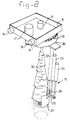
- carrier 8 with the arm 15 on it is shown in more detail in Fig. 2. It can be seen from it that carrier 8 has lateral guide rollers 16 which run in guide bars 6. Carrier 8 has on it a motor 17 provided with a drive gear 18 which meshes with a ring gear 19 of support 20. Support 20 is connected at 21 to a rotary bearing rotatable only about carrier 8.
- the arm indicated in its entirety by 15 is fitted on support 20. It comprises a guide 22 on which two cylinders, a cutting cylinder 23 and a stop cylinder 24, are fixed. Cutting cylinder 23 is firmly connected to a rod 25, which is in turn connected to the pipe 26 projecting from guide 22. Stop cylinder 24 can rest against rod 25 and is not firmly connected to it.
- a cutting element such as a spade 27 is also fitted on pipe 26.
- This spade is circular in shape and covers an angle of arc of 120°.
- the bearing at 21 in the carrier 8 and the remaining construction of support 20 and arm 15 are such that the position of cutting element 27 relative to carrier 8 is fixed. This means that cutting element 27 cannot tilt relative to the carrier 8.
- the angle which the cutting element 27 forms relative to the vertical is approximately 5°.
- Conifers 30 are also shown in the drawings. As can be seen from Fig. 1, they are disposed in three rows.
- the device 1 is placed above a number of rows of conifers.
- the driver then manoeuvres carrier 8 by means of the control panel 12 in such a way that the axis of said carrier essentially coincides with the axis of the conifer.
- Cutting element 27 is then moved down by means of cutting cylinder 23 until it is just above the ground.
- the stop cylinder 24 follows to this position.
- the cutting cylinder 23 is then operated further, and cutting element 27 is inserted into the ground.This point can be selected by the pressure in the hydraulic system increasing through the resistance encountered when cutting element 27 is entering the ground.
- Cutting element 27 is then moved back until rod 25 rests against the outward moved piston of stop cylinder 24.
- the stroke of the cutting element is limited in this way, which makes efficient operation possible, and branches and the like at the bottom side of the conifer are also prevented from being damaged.
- the upward movement of cutting element 27 the latter is moved through an angle of 120°, and the next cutting stroke is carried out.
- a third stroke is then carried out, following which a continuous round cut is achieved.
- the conifer is removed in a manner not shown. If the operator wishes to remove another conifer in the same row, he does not need to move the device 1, but it is necessary only to move carrier 8 and control point 9 to and fro in guide bars 6, 7 by means of cylinder 14.
- control point 9 and carrier 8 can also be carried out in a different way.
Landscapes
- Life Sciences & Earth Sciences (AREA)
- Environmental Sciences (AREA)
- Biodiversity & Conservation Biology (AREA)
- Ecology (AREA)
- Forests & Forestry (AREA)
- Forklifts And Lifting Vehicles (AREA)
- Hydroponics (AREA)
- Load-Engaging Elements For Cranes (AREA)
- Crystals, And After-Treatments Of Crystals (AREA)
- Cultivation Receptacles Or Flower-Pots, Or Pots For Seedlings (AREA)
Applications Claiming Priority (2)
| Application Number | Priority Date | Filing Date | Title |
|---|---|---|---|
| NL9101100A NL9101100A (nl) | 1991-06-25 | 1991-06-25 | Inrichting voor het rooien van een gewas. |
| NL9101100 | 1991-06-25 |
Publications (2)
| Publication Number | Publication Date |
|---|---|
| EP0520576A1 true EP0520576A1 (de) | 1992-12-30 |
| EP0520576B1 EP0520576B1 (de) | 1995-05-31 |
Family
ID=19859419
Family Applications (1)
| Application Number | Title | Priority Date | Filing Date |
|---|---|---|---|
| EP92201854A Expired - Lifetime EP0520576B1 (de) | 1991-06-25 | 1992-06-23 | Vorrichtung zum Heben einer Pflanze |
Country Status (4)
| Country | Link |
|---|---|
| EP (1) | EP0520576B1 (de) |
| AT (1) | ATE123206T1 (de) |
| DE (1) | DE69202732T2 (de) |
| NL (1) | NL9101100A (de) |
Cited By (3)
| Publication number | Priority date | Publication date | Assignee | Title |
|---|---|---|---|---|
| NL1016469C2 (nl) * | 2000-10-24 | 2002-04-25 | Antonius Godefridus Ma Lommers | Inrichting en werkwijze voor het aanbrengen van een rondgaande scheiding tussen een kluit en de kluit omringende grond. |
| EP1597964A1 (de) * | 2004-05-18 | 2005-11-23 | Kim Thomsen | Verfahren zum Freischneiden von Pflanzen aus dem Erdbereich und Schneidevorrichtung zum Schneiden des den zumindest eine Pflanze umgebenden Erdbereichs |
| CN112889616A (zh) * | 2020-12-31 | 2021-06-04 | 东莞市顺成园林绿化有限公司 | 一种园林苗木种植装置及种植方法 |
Families Citing this family (2)
| Publication number | Priority date | Publication date | Assignee | Title |
|---|---|---|---|---|
| WO2004103063A1 (en) * | 2003-05-22 | 2004-12-02 | Mark Geoffrey Crumblin | Aerial saw |
| CN108713378B (zh) * | 2018-04-26 | 2020-06-30 | 重庆松鹤农业综合开发有限公司 | 用于果树的移栽装置 |
Citations (4)
| Publication number | Priority date | Publication date | Assignee | Title |
|---|---|---|---|---|
| US3017708A (en) * | 1958-03-24 | 1962-01-23 | Reed Roller Bit Co | Tree excavator and transplanter |
| US3427734A (en) * | 1966-05-26 | 1969-02-18 | Edwin J Eberhart | Tree digger construction |
| US3594931A (en) * | 1968-11-12 | 1971-07-27 | Campbell S Brower | Apparatus for excavating plants |
| DE2104709A1 (de) * | 1971-02-02 | 1972-08-24 | Bernhard Strautmann & Söhne, 4501 Laer | Gerät zum Entnehmen von Futterportionen aus Flach- oder Fahrsilos |
-
1991
- 1991-06-25 NL NL9101100A patent/NL9101100A/xx not_active Application Discontinuation
-
1992
- 1992-06-23 DE DE69202732T patent/DE69202732T2/de not_active Expired - Fee Related
- 1992-06-23 EP EP92201854A patent/EP0520576B1/de not_active Expired - Lifetime
- 1992-06-23 AT AT92201854T patent/ATE123206T1/de not_active IP Right Cessation
Patent Citations (4)
| Publication number | Priority date | Publication date | Assignee | Title |
|---|---|---|---|---|
| US3017708A (en) * | 1958-03-24 | 1962-01-23 | Reed Roller Bit Co | Tree excavator and transplanter |
| US3427734A (en) * | 1966-05-26 | 1969-02-18 | Edwin J Eberhart | Tree digger construction |
| US3594931A (en) * | 1968-11-12 | 1971-07-27 | Campbell S Brower | Apparatus for excavating plants |
| DE2104709A1 (de) * | 1971-02-02 | 1972-08-24 | Bernhard Strautmann & Söhne, 4501 Laer | Gerät zum Entnehmen von Futterportionen aus Flach- oder Fahrsilos |
Cited By (3)
| Publication number | Priority date | Publication date | Assignee | Title |
|---|---|---|---|---|
| NL1016469C2 (nl) * | 2000-10-24 | 2002-04-25 | Antonius Godefridus Ma Lommers | Inrichting en werkwijze voor het aanbrengen van een rondgaande scheiding tussen een kluit en de kluit omringende grond. |
| EP1597964A1 (de) * | 2004-05-18 | 2005-11-23 | Kim Thomsen | Verfahren zum Freischneiden von Pflanzen aus dem Erdbereich und Schneidevorrichtung zum Schneiden des den zumindest eine Pflanze umgebenden Erdbereichs |
| CN112889616A (zh) * | 2020-12-31 | 2021-06-04 | 东莞市顺成园林绿化有限公司 | 一种园林苗木种植装置及种植方法 |
Also Published As
| Publication number | Publication date |
|---|---|
| DE69202732T2 (de) | 1996-01-18 |
| DE69202732D1 (de) | 1995-07-06 |
| ATE123206T1 (de) | 1995-06-15 |
| NL9101100A (nl) | 1993-01-18 |
| EP0520576B1 (de) | 1995-05-31 |
Similar Documents
| Publication | Publication Date | Title |
|---|---|---|
| US4194347A (en) | Method and apparatus for shaking trees grown in rows | |
| US20040050309A1 (en) | Tree spade system | |
| EP2441321A2 (de) | Landwirtschaftliches Gerät zum Unterstützen und zur Betätigung verschiedener operativen Einheiten, welches geeignet ist zum Arbeiten auf Kulturreihen. | |
| US6634162B1 (en) | Simultaneous processing of multiple rows of plants, especially trellised rows | |
| EP0520576B1 (de) | Vorrichtung zum Heben einer Pflanze | |
| CN108077016A (zh) | 一种道路景观树木自动栽种装置 | |
| EP0609148A1 (de) | Selbstfahrendhandhabungsmaschine, insbesondere für Landwirtschaft und Gartenbau | |
| US4355475A (en) | Root grubbing plow | |
| US4781228A (en) | Tree pruner | |
| DK1488685T4 (da) | Høbjergningsmaskine | |
| EP4000383B1 (de) | Mobiler arbeitsplatz für den gartenbau | |
| CN218977352U (zh) | 一种用于水培蔬菜的采摘机器人 | |
| HU199202B (en) | Harrow | |
| US3078602A (en) | Transplanting implement | |
| US4494325A (en) | Shrub-lifting machine with piston controlled anchor | |
| US6343659B1 (en) | Mini shrub spader | |
| CA2273640C (en) | A mini shrub spader | |
| CN214508518U (zh) | 一种挖树机 | |
| US20080034726A1 (en) | Reversible directible harvesting machine and method for carrying out the harvesting process with said machine | |
| AU2016101045A4 (en) | Agricultural apparatus | |
| US2835992A (en) | Plant digging machine | |
| CA1080584A (en) | Flailing machine for felled trees | |
| FR2494082A1 (fr) | Dispositif monte sur un tracteur pour ebourgeonner, epamprer et pincer la vigne | |
| CN223584922U (zh) | 一种果木移植拾取装置 | |
| CN219555718U (zh) | 茶树台刈机 |
Legal Events
| Date | Code | Title | Description |
|---|---|---|---|
| PUAI | Public reference made under article 153(3) epc to a published international application that has entered the european phase |
Free format text: ORIGINAL CODE: 0009012 |
|
| AK | Designated contracting states |
Kind code of ref document: A1 Designated state(s): AT BE CH DE DK ES FR GB GR IT LI NL PT SE |
|
| 17P | Request for examination filed |
Effective date: 19930513 |
|
| 17Q | First examination report despatched |
Effective date: 19930625 |
|
| GRAA | (expected) grant |
Free format text: ORIGINAL CODE: 0009210 |
|
| AK | Designated contracting states |
Kind code of ref document: B1 Designated state(s): AT BE CH DE DK ES FR GB GR IT LI NL PT SE |
|
| PG25 | Lapsed in a contracting state [announced via postgrant information from national office to epo] |
Ref country code: DK Effective date: 19950531 Ref country code: GR Free format text: LAPSE BECAUSE OF FAILURE TO SUBMIT A TRANSLATION OF THE DESCRIPTION OR TO PAY THE FEE WITHIN THE PRESCRIBED TIME-LIMIT Effective date: 19950531 Ref country code: LI Effective date: 19950531 Ref country code: ES Free format text: THE PATENT HAS BEEN ANNULLED BY A DECISION OF A NATIONAL AUTHORITY Effective date: 19950531 Ref country code: CH Effective date: 19950531 |
|
| REF | Corresponds to: |
Ref document number: 123206 Country of ref document: AT Date of ref document: 19950615 Kind code of ref document: T |
|
| ITF | It: translation for a ep patent filed | ||
| REF | Corresponds to: |
Ref document number: 69202732 Country of ref document: DE Date of ref document: 19950706 |
|
| PG25 | Lapsed in a contracting state [announced via postgrant information from national office to epo] |
Ref country code: PT Effective date: 19950831 Ref country code: SE Effective date: 19950831 |
|
| REG | Reference to a national code |
Ref country code: CH Ref legal event code: PL |
|
| ET | Fr: translation filed | ||
| PLBE | No opposition filed within time limit |
Free format text: ORIGINAL CODE: 0009261 |
|
| STAA | Information on the status of an ep patent application or granted ep patent |
Free format text: STATUS: NO OPPOSITION FILED WITHIN TIME LIMIT |
|
| 26N | No opposition filed | ||
| PGFP | Annual fee paid to national office [announced via postgrant information from national office to epo] |
Ref country code: GB Payment date: 19970613 Year of fee payment: 6 |
|
| PGFP | Annual fee paid to national office [announced via postgrant information from national office to epo] |
Ref country code: FR Payment date: 19970617 Year of fee payment: 6 |
|
| PGFP | Annual fee paid to national office [announced via postgrant information from national office to epo] |
Ref country code: AT Payment date: 19970624 Year of fee payment: 6 Ref country code: BE Payment date: 19970624 Year of fee payment: 6 |
|
| PGFP | Annual fee paid to national office [announced via postgrant information from national office to epo] |
Ref country code: NL Payment date: 19970630 Year of fee payment: 7 |
|
| PGFP | Annual fee paid to national office [announced via postgrant information from national office to epo] |
Ref country code: DE Payment date: 19970722 Year of fee payment: 6 |
|
| PG25 | Lapsed in a contracting state [announced via postgrant information from national office to epo] |
Ref country code: GB Free format text: LAPSE BECAUSE OF NON-PAYMENT OF DUE FEES Effective date: 19980623 Ref country code: AT Free format text: LAPSE BECAUSE OF NON-PAYMENT OF DUE FEES Effective date: 19980623 |
|
| PG25 | Lapsed in a contracting state [announced via postgrant information from national office to epo] |
Ref country code: BE Free format text: LAPSE BECAUSE OF NON-PAYMENT OF DUE FEES Effective date: 19980630 |
|
| BERE | Be: lapsed |
Owner name: J. VAN DAM B.V. Effective date: 19980630 |
|
| GBPC | Gb: european patent ceased through non-payment of renewal fee |
Effective date: 19980623 |
|
| PG25 | Lapsed in a contracting state [announced via postgrant information from national office to epo] |
Ref country code: FR Free format text: LAPSE BECAUSE OF NON-PAYMENT OF DUE FEES Effective date: 19990226 |
|
| PG25 | Lapsed in a contracting state [announced via postgrant information from national office to epo] |
Ref country code: DE Free format text: LAPSE BECAUSE OF NON-PAYMENT OF DUE FEES Effective date: 19990401 |
|
| REG | Reference to a national code |
Ref country code: FR Ref legal event code: ST |
|
| PG25 | Lapsed in a contracting state [announced via postgrant information from national office to epo] |
Ref country code: NL Free format text: LAPSE BECAUSE OF NON-PAYMENT OF DUE FEES Effective date: 20000101 |
|
| NLV4 | Nl: lapsed or anulled due to non-payment of the annual fee |
Effective date: 20000101 |
|
| PG25 | Lapsed in a contracting state [announced via postgrant information from national office to epo] |
Ref country code: IT Free format text: LAPSE BECAUSE OF NON-PAYMENT OF DUE FEES;WARNING: LAPSES OF ITALIAN PATENTS WITH EFFECTIVE DATE BEFORE 2007 MAY HAVE OCCURRED AT ANY TIME BEFORE 2007. THE CORRECT EFFECTIVE DATE MAY BE DIFFERENT FROM THE ONE RECORDED. Effective date: 20050623 |