EP0520903B1 - Verfahren zur Bestimmung der horizontalen und/oder vertikalen Permeabilität einer irdischen Formation - Google Patents
Verfahren zur Bestimmung der horizontalen und/oder vertikalen Permeabilität einer irdischen Formation Download PDFInfo
- Publication number
- EP0520903B1 EP0520903B1 EP92401806A EP92401806A EP0520903B1 EP 0520903 B1 EP0520903 B1 EP 0520903B1 EP 92401806 A EP92401806 A EP 92401806A EP 92401806 A EP92401806 A EP 92401806A EP 0520903 B1 EP0520903 B1 EP 0520903B1
- Authority
- EP
- European Patent Office
- Prior art keywords
- formation
- value
- aperture
- fluid
- pressure
- Prior art date
- Legal status (The legal status is an assumption and is not a legal conclusion. Google has not performed a legal analysis and makes no representation as to the accuracy of the status listed.)
- Expired - Lifetime
Links
Images


Classifications
-
- E—FIXED CONSTRUCTIONS
- E21—EARTH OR ROCK DRILLING; MINING
- E21B—EARTH OR ROCK DRILLING; OBTAINING OIL, GAS, WATER, SOLUBLE OR MELTABLE MATERIALS OR A SLURRY OF MINERALS FROM WELLS
- E21B49/00—Testing the nature of borehole walls; Formation testing; Methods or apparatus for obtaining samples of soil or well fluids, specially adapted to earth drilling or wells
- E21B49/008—Testing the nature of borehole walls; Formation testing; Methods or apparatus for obtaining samples of soil or well fluids, specially adapted to earth drilling or wells by injection test; by analysing pressure variations in an injection or production test, e.g. for estimating the skin factor
-
- E—FIXED CONSTRUCTIONS
- E21—EARTH OR ROCK DRILLING; MINING
- E21B—EARTH OR ROCK DRILLING; OBTAINING OIL, GAS, WATER, SOLUBLE OR MELTABLE MATERIALS OR A SLURRY OF MINERALS FROM WELLS
- E21B49/00—Testing the nature of borehole walls; Formation testing; Methods or apparatus for obtaining samples of soil or well fluids, specially adapted to earth drilling or wells
- E21B49/08—Obtaining fluid samples or testing fluids, in boreholes or wells
- E21B49/10—Obtaining fluid samples or testing fluids, in boreholes or wells using side-wall fluid samplers or testers
Definitions
- the invention concerns methods for estimating the horizontal and/or vertical components of permeability of an anisotropic earth formation.
- the permeability of an earth formation containing valuable resources is a parameter of major significance to their economic production.
- valuable resources such as liquid or gaseous hydrocarbons
- These resources can be located by borehole logging to measure such parameters as the resistivity and porosity of the formation in the vicinity of a borehole traversing the formation.
- Such measurements enable porous zones to be identified and their water saturation (percentage of pore space occupied by water) to be estimated.
- a value of water saturation significantly less than one is taken as being indicative of the presence of hydrocarbons, and may also be used to estimate their quantity.
- this information alone is not necessarily adequate for a decision on whether the hydrocarbons are economically producible.
- the pore spaces containing the hydrocarbons may be isolated or only slightly interconnected, in which case the hydrocarbons will be unable to flow through the formation to the borehole.
- the ease with which fluids can flow through the formation, the permeability should preferably exceed some threshold value to assure the economic feasibility of turning the borehole into a producing well.
- This threshold value may vary depending on such characteristics as the viscosity of the fluid. For example, a highly viscous oil will not flow easily in low permeability conditions and if water injection is to be used to promote production there may be a risk of premature water breakthrough at the producing well.
- the permeability of a formation is not necessarily isotropic.
- the permeability of sedimentary rock in a generally horizontal direction may be different from, and typically greater than, the value for flow in a generally vertical direction. This frequently arises from alternating horizontal layers consisting of large and small size formation particles such as different sized sand grains or clay.
- the permeability is strongly anisotropic, determining the existence and degree of the anisotropy is important to economic production of hydrocarbons.
- One technique involves measurements made with a repeat formation testing tool of the type described in U.S. Patents No. 3,780,575 to Urbanosky and 3,952,588 to Whitten, such as the Schlumberger RFpM tool.
- a tool of this type provides the capability for repeatedly taking two successive "pretest" samples at different flowrates from a formation via a single probe inserted into a borehole wail and having an aperture of circular cross-section. The fluid pressure is monitored and recorded throughout the sample extraction period and for a period of time thereafter. Analysis of the pressure variations with time during the sample extractions (“draw-down") and the subsequent return to initial conditions (“build-up”) enables a value for an effective formation permeability to be derived for each of the draw-down and build-up phases of operation.
- Figure 1 illustrates schematically the principal elements of a tool employed in taking "pretest" samples.
- the tip 110 of a probe is inserted through mud cake 112 into the borehole wall. Mud cake 112 and a packer 114 hydraulically seal the probe tip 110 with respect to the formation 116.
- the probe includes a filter 118 disposed in the probe aperture and a filter-cleaning piston 120.
- the pretest system comprises chambers 122 and 124 and associated pistons 126 and 128. Pistons 126 and 128 are retracted in sequence each time the probe is set. Piston 126 is withdrawn first, drawing in formation fluid at a flow rate of, for example, 50 cc/min.
- Figure 1 shows the system in mid-sequence, with piston 126 withdrawn.
- a strain gauge sensor 132 measures pressure in line 134 continuously during the sequence. When the probe is retracted, the pistons 126 and 128 are moved to expel the fluid, and filter cleaning piston 120 pushes debris from the probe.
- FIG. 2 shows a typical analog pressure recording during pretest.
- a pressure draw-down ⁇ P 1 is recorded as piston 126 is withdrawn during a time period Ti
- a pressure draw-down Ap 2 is recorded as piston 128 is withdrawn during a time period T 2 .
- pretest chambers 122 and 124 are full (at time t 2 )
- the pressure begins to build up over a time period At toward a final pressure, that of the formation.
- the permeability has been estimated by analyzing the pressure recording during either buildup or drawdown. As illustrated in Figure 3, the point 310 at which the probe tip 110 is applied to the wall of the borehole 312 coincides with the center of the latter stage of the pressure disturbance during buildup. From the perspective of a coordinate system whose axes have been suitably stretched by an amount dictated by the horizontal and vertical components of the permeability, the pressure disturbance appears to be propagating spherically outward from the probe tip 110. Thus the analysis yields a single "spherical" permeability value, consisting of a specific combination of both the horizontal and vertical components of the permeability. During drawdown, the pressure disturbance has only been analysed for the case of a homogeneous formation with isotropic permeability.
- FIG. 4 shows in schematic form a borehole logging device 400 useful in practicing the method.
- formation pressure responses vs. time are measured at two observation probes (402 and 404) of circular cross-section as a transient pressure disturbance is established in the formation 406 surrounding the borehole 408 by means of a "source" probe 410.
- the observation probes are spaced apart in the borehole, probe 404 (the “horizontal” probe) being displaced from source probe 410 in the lateral direction and probe 402 (the “vertical” probe) being displaced from source probe 410 in the longitudinal direction.
- Hydraulic properties of the surrounding formation such as values of permeability and hydraulic anisotropy, are derived from the measured pressure responses.
- the longitudinally-spaced observation probes are set so that they straddle a hydraulic barrier in the formation (e.g., a formation layer of low permeability relative to the layers in which the probes are set), the values determined for vertical permeability and hydraulic anisotropy may differ significantly from the local characteristics of the formation layers above and below the barrier.
- the technique of the Lasseter patent may require simultaneous hydraulic seating of three probes, though it may be possible to make both horizontal and vertical measurements with only two probes. Accurate measurement may be prevented if one or more of the probes fails to seal properly, such as where the borehole surface is uneven. While even a single-probe system can encounter seating problems, the need for simultaneous seating of multiple probes may increase the difficulty of obtaining the desired measurement.
- the measured build-up and draw-down data are analyzed to derive separate values for horizontal and vertical formation permeability. This is possible because they successfully analyze the pressure disturbance during draw-down for an anisotropic formation.
- This technique offers a localized determination of hydraulic anisotropy, and avoids the need to incorporate data from other logging tools or core analysis. It has the disadvantage that it relies on measurement of pressure build-up, which demands an extremely fast- responding pressure transducer with a very high sensitivity.
- Pressure draw-down is a relatively robust measurement -- pressure is measured before and after the pressure disturbance caused by fluid extraction. Pressure build-up is a more delicate measurement because the rate of pressure recovery must be measured accurately as the detected pressure asymptotically approaches formation pressure (the pressure recovers at a rate of 1/t3/2).
- a further technique for determining permeability is performed in the laboratory using formation samples and a laboratory instrument known as a mini-permeameter.
- the instrument has an injection probe with a nozzle of circular cross-section which is pressed against the surface of a sample and appropriately sealed. Pressurized gas flows through the injection nozzle into the rock sample as gas flow and injection pressure are measured.
- the process may be performed on a first face 510 having its longitudinal (z) axis perpendicular to the bedding planes of a formation sample 500 and on a second face 520 having its longitudinal (x or y) axis parallel to the bedding planes of the formation sample.
- the measured flows through the sample are used in determining permeability. See, for example, R.
- the mini-permeameter is a laboratory instrument, and cannot be used to make in situ measurements in a well bore. Thus, it can only be used to make the necessary measurements if formation core samples are available, which is not always the case. Moreover, it entails destruction of portions of the core sample, as a smaller sample having a smooth face parallel to and perpendicular to the bedding planes must be cut from the sample for testing. Also, the mini-permeameter measures the permeability of isotropic samples. In the case of an anisotropic sample, it only gives an effective value. Thus, it would only give an effective vertical and effective horizontal permeability from the two faces 510 and 520, respectively.
- fluid flow measurements are made in situ using a repeat formation tester with a modified probe aperture, or a mini-permeameter with a modified probe aperture.
- the modified probe aperture has an elongate cross-section, such as elliptic or rectangular.
- a first flow measurement is made with the longer dimension of the probe aperture in a first orientation (e.g., horizontal or vertical) with respect to the formation bedding planes.
- a second flow measurement is made with the probe aperture orthogonal to the first orientation, or with a probe aperture of non-elongate (e.g., circular) cross-section. Simultaneous equations relating values of known and measured quantities are solved to obtain estimates of local horizontal and/or vertical formation permeability.
- the invention concerns nondestructive techniques for estimating the horizontal and/or vertical components of permeability of an anisotropic earth formation.
- formations of interest typically comprise sedimentary rock, it is assumed that the formation is isotropic in the horizontal directions, and has a smaller permeability in the vertical direction than in the horizontal.
- the "horizontal” directions are those generally parallel to the bedding planes of the rock, and the “vertical” direction is generally perpendicular to the bedding planes of the rock.
- the term “formation” comprises a formation sample, such as a core plug taken from a borehole.
- “formation fluid” may be a liquid or a gas such as atmospheric air. It is noted that where a gas zone under consideration has been contaminated with liquid, measurements should be treated as if the formation sample is a liquid.
- flow measurements are made to obtain values from which the permeability components of an earth formation are estimated.
- the flow measurements may be conducted in situ and/or in the laboratory using formation samples. In situ, measurements are preferably made in a borehole with a formation test tool having a probe aperture modified as described below.
- Formation test tools which may be employed include the Schlumberger RFTTM tester, MRTTTM tester and MDTTM tester. Laboratory measurements and measurements on outcrops are preferably made with a mini-permeameter having a probe aperture modified as described below.
- the technique can be performed using a single probe. Pressure measurements are taken at the probe, through which fluid is forced to flow under substantially steady-state, single-phase conditions. For downhole measurements, the flow is preferably induced by drawing formation fluid into the tool through the probe ("draw-down”). Alternately, fluid may be injected into the formation through the probe ("injection”). Gas injection is preferred for laboratory measurements with formation samples. Whether fluid is drawn into the probe or injected out through the probe, a pressure disturbance is caused in the formation fluid.
- the technique may be used to determine permeability on a length scale similar to that of the Hassler core.
- permeability determined by this technique should be comparable to that obtained using the recognized standard procedure in the petroleum industry.
- Preferred methods of estimating horizontal and/or vertical permeability in accordance with the invention differ in at least two significant ways from the prior art methods described above.
- a probe having an aperture of non-circular cross-section is employed.
- the probe is that part of the tool or instrument in contact with the formation or formation specimen. Fluid is displaced through the probe aperture in making a measurement.
- the aperture is preferably shaped as a narrow slit, a small aspect ratio (width / length) being of more importance than the exact shape of the cross-section.
- the slit shape allows fluid to be drawn or injected in a pattern which corresponds to the direction of measurement. For example, Figure 6 shows the probe oriented horizontally.
- the fluid enters the probe (in the case of draw-down) along the vertical axis Y.
- Figure 7 shows the probe oriented vertically.
- the flow lines in Figure 7 show the fluid entering the probe (in the case of a draw-down) along a horizontal axis X.
- the limit on the smallness of the aspect ratio results from a desire to avoid clogging, and the size of the diameter (maximum length) of the probe.
- the aspect ratio as defined (width/length) is less than 1.0.
- measurements are taken during two pressure disturbances (e.g., during two draw-downs), with the aperture oriented in two different directions with respect to the formation or formation specimen during the two measurements.
- the aperture is oriented in a first direction (e.g., horizontal) during a first draw-down, and is oriented in a second direction (e.g., vertical) orthogonal to the first direction during a second draw-down.
- the "orientation" is the direction of the longest dimension of the aperture cross-section.
- the non-circular aperture cross-section may be generally elliptic or rectangular or of some other elongate or slit-like form.
- pressure draw-downs caused by withdrawal of fluid from the formation
- pressure increases caused by injection of fluid into the formation may be used.
- a combination of a pressure draw-down and a pressure increase (injection) may be used in place of two draw-downs.
- Probes with two different aperture cross-sections may be used for the two pressure disturbance (drawdown and/or injection) measurements -- for example, one of the aperture cross-sections can be circular, provided the other aperture cross-section has a small aspect ratio (ratio of width to length).
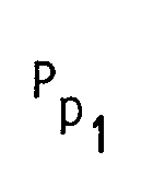
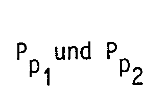
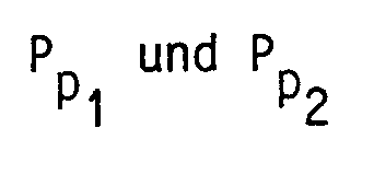
- Determination of horizontal and/or vertical permeability in accordance with the preferred embodiments is based upon our derived relationship among the following parameters: the volumetric flowrate, Q, and the viscosity, ⁇ , of the fluid forced to pass through the aperture of the probe during draw-down or injection, the horizontal, k h , and vertical, kv, components of the permeability of the formation, the pressure at the probe, Pp , the pressure of the formation far from the probe (equivalent to the pressure measured by the probe when the formation fluid is in its undisturbed state), Pf, and the probe aperture dimensions 2 x l h and 2 x l v.
- Equation (1) the "k v " term, kv( ⁇ 2 P/ ⁇ Z 2 ), relates to formation permeability in the vertical direction and the "k h " term, k h ( ⁇ 2 P/ ⁇ x 2 + ⁇ 2 Play 2 ), relates to formation permeability in an isotropic horizontal plane.
- Equation (5) the "k v " term relates to formation permeability in the vertical direction and the “k h “ term relates to formation permeability in an isotropic horizontal plane.
- volumetric flow rate Q
- Ap denotes the area of the aperture of the probe.
- Ap denotes the area of the aperture of the probe.
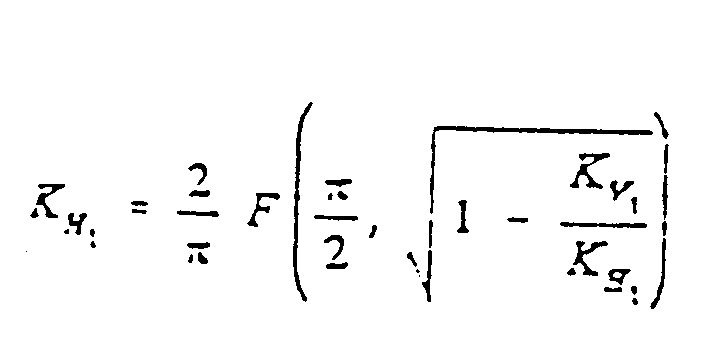
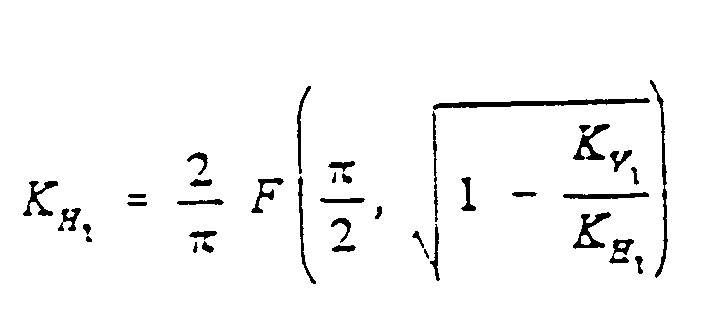
- F denotes the complete elliptic integral of the first kind
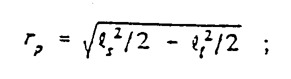
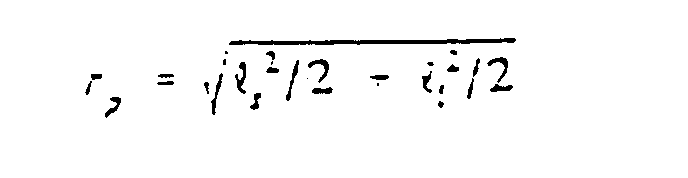
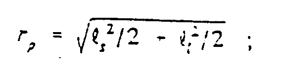
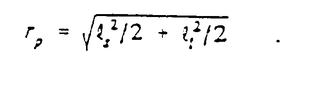
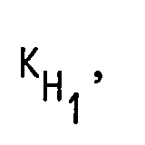
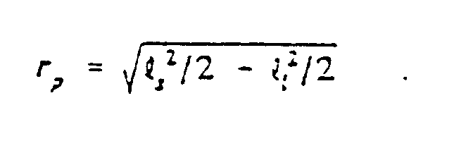
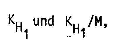
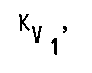
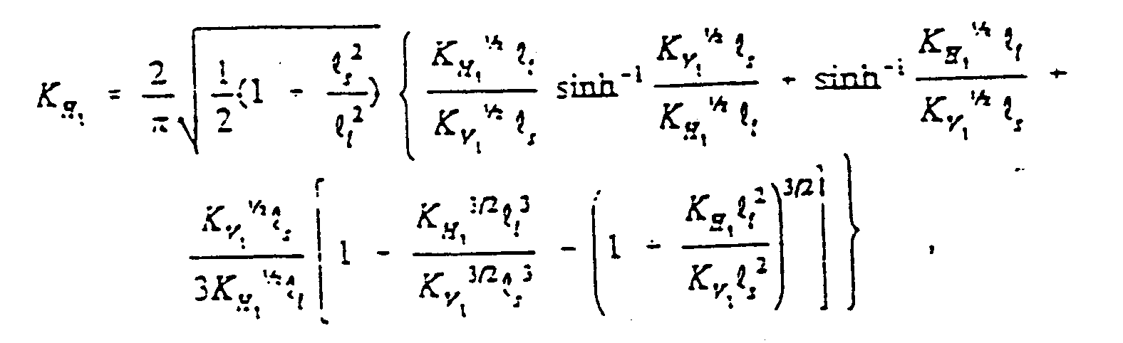
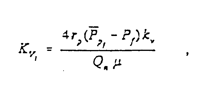
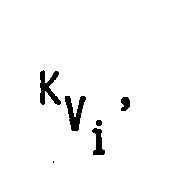
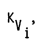
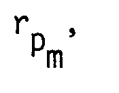
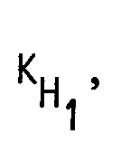
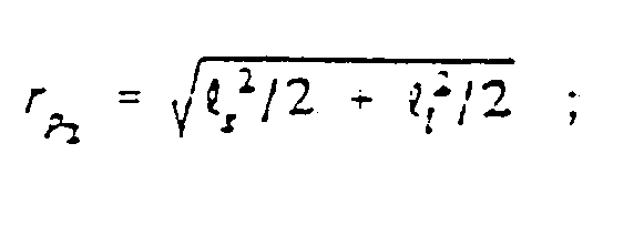
- rp denotes the effective probe radius, defined as K H and K v denote the dimensionless horizontal component and the dimensionless vertical component of the permeability, respectively.
- Figure 9 plots values of permeability, k, versus preferred ratios of Rp ad /Rp robe , where Rp ad is the radius of the impermeable pad and Rp robe is the radius of the probe aperture. Pad dimensions for in situ, measurement are less critical, in part due to the sealing effect of mud-cake at the borehole wall.
- the dimensionless horizontal and vertical components of the permeability are determined as follows. Let 2 x l and 2 x l, denote the smallest and largest dimensions of the aperture of the probe, respectively. It will be recalled that we are interested in any aperture having a small aspect ratio, i.e., the ratio l s /l l is a small number.
- a vertical orientation of the probe aperture assumes l h equals l s , and l v equals l l .
- a horizontal orientation of the probe assumes l h equals l l , and l v equals l s . It It is further assumed that two drawdowns are performed.
- the first drawdown fluid flows through the probe at a volumetric flowrate corresponding to Q 1 , with the probe oriented vertically.
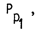
- the second drawdown fluid flows through the probe at a volumetric flowrate corresponding to Q 2 , with the probe oriented horizontally. It is assumed that the values of Q 1 and Q 2 are known; they need not be equal. This gives rise to the following two simultaneous equations containing only two unknowns, and The subscripts 1 and 2 refer to the pressure at the probe and flow rate through the probe corresponding to the first draw-down and the second draw-down, respectively, in the definitions of K H and K v .
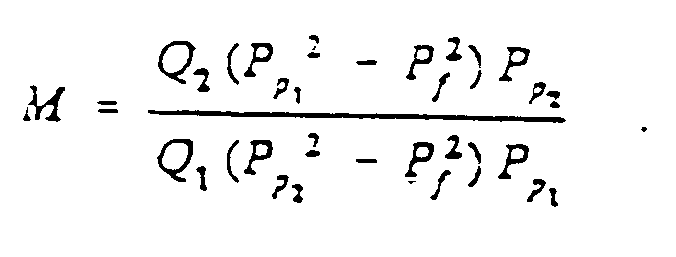
- the definition of the quantity M for liquid is given by:
- the definition of the quantity M for gas is given by:
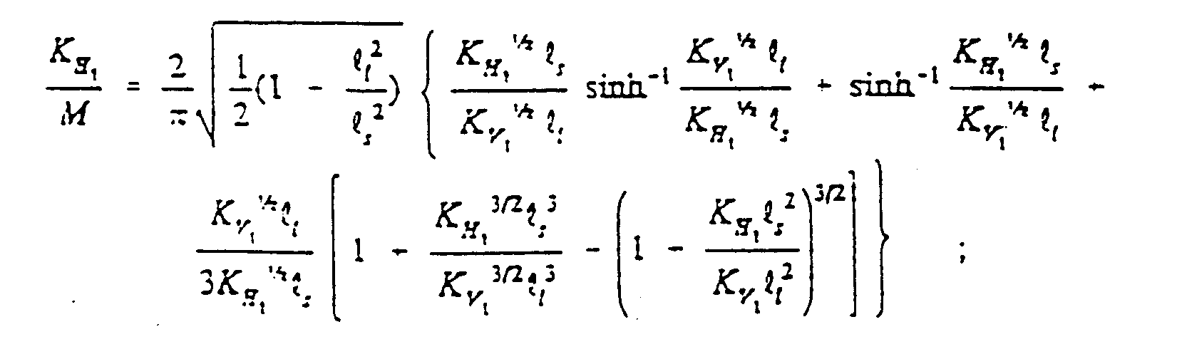
- the value of quantity M is readily obtained from the measured pressures and known flow rates, and is equivalent to both and to The values of hence the values of k h and k v , are determined from the solution to the above set of equations.
- Table 1 Values for can be obtained by using a table such as Table 1 shown in Figure 10.
- the table is constructed from the above set of equations by evaluating the quantities M, over a range of values of the anisotropy, k h /k v , of the formation, for a given aperture aspect ratio l s /l l .
- the evaluation makes use of the facts that and the value of l s /l l is known.
- equation (14) is used to evaluate and equation (15) is used to evaluate
- the value of M is obtained by evaluating the ratio
- a value of M is calculated from measured pressure values and known flow rates of a set of pretest measurements made with the probe aperture oriented in the vertical direction during a first draw-down and in the horizontal direction during a second draw-flown, or vice versa (see equation (16) for liquids and equation (17) for gases).
- the values of in the same row as the calculated value of M represent the solution to the above set of equations. For example, if l s /l l equals 0.2 and M equals 0.6732, then Table 1 ( Figure 10) gives a value for of 1.905 and a value for of 0.1905.
- Table 2 ( Figure 13) gives values for an elliptic aperture having an aspect ratio l s /l l of 0.01 oriented vertically and horizontally.
- the data of Table 2 is presented graphically in Figures 14 and 15.
- Figure 14 the values of the anisotropy, k v /k h , and the dimensionless components of the permeability, K H and K v , are plotted versus values of calculated measurement factor M for an elliptic probe aperture having an aspect ratio of 0.01.
- the plotted values correspond to data presented in the first, second, third, and sixth columns of Table 2.
- the subscript 1 denotes data characterizing the vertically oriented probe.
- the probe is applied to the formation (or formation sample) with the aperture oriented in a first direction: preferably either horizontal or vertical (step 1610).
- the formation pressure is measured at the probe (step 1620). Fluid is displaced through the probe for a first time period at a flow rate Q 1 (step 1630). Pressure at the probe is measured at the end of the first time period (step 1640).
- the probe is then withdrawn, rotated 90 ° , and reapplied to the formation (step 1650). Fluid is displaced through the probe for a second time period at a flow rate Q 2 (step 1660). Pressure at the probe is measured at the end of the second time period (step 1670). Viscosity of the fluid is measured (step 1680). Values of horizontal permeability k h and/or ky are determined from the aperture dimensions, the measured pressures, the flow rates, and the fluid viscosity.
Landscapes
- Geology (AREA)
- Life Sciences & Earth Sciences (AREA)
- Engineering & Computer Science (AREA)
- Mining & Mineral Resources (AREA)
- Environmental & Geological Engineering (AREA)
- Fluid Mechanics (AREA)
- Physics & Mathematics (AREA)
- General Life Sciences & Earth Sciences (AREA)
- Geochemistry & Mineralogy (AREA)
- Chemical & Material Sciences (AREA)
- Analytical Chemistry (AREA)
- Investigation Of Foundation Soil And Reinforcement Of Foundation Soil By Compacting Or Drainage (AREA)
- Measuring Volume Flow (AREA)
- Separation Using Semi-Permeable Membranes (AREA)
- Foundations (AREA)
Claims (21)










































Applications Claiming Priority (2)
| Application Number | Priority Date | Filing Date | Title |
|---|---|---|---|
| US722052 | 1991-06-27 | ||
| US07/722,052 US5265015A (en) | 1991-06-27 | 1991-06-27 | Determining horizontal and/or vertical permeability of an earth formation |
Publications (3)
| Publication Number | Publication Date |
|---|---|
| EP0520903A2 EP0520903A2 (de) | 1992-12-30 |
| EP0520903A3 EP0520903A3 (en) | 1993-05-19 |
| EP0520903B1 true EP0520903B1 (de) | 1995-10-25 |
Family
ID=24900327
Family Applications (1)
| Application Number | Title | Priority Date | Filing Date |
|---|---|---|---|
| EP92401806A Expired - Lifetime EP0520903B1 (de) | 1991-06-27 | 1992-06-25 | Verfahren zur Bestimmung der horizontalen und/oder vertikalen Permeabilität einer irdischen Formation |
Country Status (5)
| Country | Link |
|---|---|
| US (1) | US5265015A (de) |
| EP (1) | EP0520903B1 (de) |
| AU (1) | AU656381B2 (de) |
| DE (1) | DE69205628D1 (de) |
| NO (1) | NO305575B1 (de) |
Families Citing this family (51)
| Publication number | Priority date | Publication date | Assignee | Title |
|---|---|---|---|---|
| US5279153A (en) * | 1991-08-30 | 1994-01-18 | Schlumberger Technology Corporation | Apparatus for determining horizontal and/or vertical permeability of an earth formation |
| US5602334A (en) * | 1994-06-17 | 1997-02-11 | Halliburton Company | Wireline formation testing for low permeability formations utilizing pressure transients |
| FR2739932B1 (fr) * | 1995-10-11 | 1997-12-12 | Inst Francais Du Petrole | Methode et dispositif pour caracteriser l'anisotropie de permeabilite d'un milieu poreux |
| US5770798A (en) * | 1996-02-09 | 1998-06-23 | Western Atlas International, Inc. | Variable diameter probe for detecting formation damage |
| RU2159849C2 (ru) * | 1998-12-08 | 2000-11-27 | Общество с ограниченной ответственностью "Уфимский научно-исследовательский и проектно-инженерный центр "Нефтегаз-2" | Способ оценки проницаемости пород и дебитов нефтегазовых скважин |
| HK1047109A1 (zh) * | 1999-10-15 | 2003-02-07 | University Of Massachusetts | 作为指定基因干预工具的rna干预轨迹基因 |
| AU1939400A (en) * | 1999-12-14 | 2001-12-03 | Cristina Crawford | Multi-directional permeameter |
| US6609568B2 (en) | 2000-07-20 | 2003-08-26 | Baker Hughes Incorporated | Closed-loop drawdown apparatus and method for in-situ analysis of formation fluids |
| US7032661B2 (en) | 2001-07-20 | 2006-04-25 | Baker Hughes Incorporated | Method and apparatus for combined NMR and formation testing for assessing relative permeability with formation testing and nuclear magnetic resonance testing |
| US7126332B2 (en) | 2001-07-20 | 2006-10-24 | Baker Hughes Incorporated | Downhole high resolution NMR spectroscopy with polarization enhancement |
| US7011155B2 (en) | 2001-07-20 | 2006-03-14 | Baker Hughes Incorporated | Formation testing apparatus and method for optimizing draw down |
| US7395703B2 (en) | 2001-07-20 | 2008-07-08 | Baker Hughes Incorporated | Formation testing apparatus and method for smooth draw down |
| US6658930B2 (en) | 2002-02-04 | 2003-12-09 | Halliburton Energy Services, Inc. | Metal pad for downhole formation testing |
| AU2003231797C1 (en) * | 2002-05-17 | 2010-02-18 | Halliburton Energy Services, Inc. | MWD formation tester |
| EP1512152A4 (de) * | 2002-05-17 | 2006-03-08 | Halliburton Energy Serv Inc | Verfahren und vorrichtung zur mwd-bildungsprüfung |
| US6719049B2 (en) * | 2002-05-23 | 2004-04-13 | Schlumberger Technology Corporation | Fluid sampling methods and apparatus for use in boreholes |
| US7178591B2 (en) * | 2004-08-31 | 2007-02-20 | Schlumberger Technology Corporation | Apparatus and method for formation evaluation |
| US8555968B2 (en) * | 2002-06-28 | 2013-10-15 | Schlumberger Technology Corporation | Formation evaluation system and method |
| US8210260B2 (en) | 2002-06-28 | 2012-07-03 | Schlumberger Technology Corporation | Single pump focused sampling |
| US8899323B2 (en) | 2002-06-28 | 2014-12-02 | Schlumberger Technology Corporation | Modular pumpouts and flowline architecture |
| US6832515B2 (en) | 2002-09-09 | 2004-12-21 | Schlumberger Technology Corporation | Method for measuring formation properties with a time-limited formation test |
| US7128144B2 (en) * | 2003-03-07 | 2006-10-31 | Halliburton Energy Services, Inc. | Formation testing and sampling apparatus and methods |
| US9376910B2 (en) | 2003-03-07 | 2016-06-28 | Halliburton Energy Services, Inc. | Downhole formation testing and sampling apparatus having a deployment packer |
| WO2004081344A2 (en) | 2003-03-10 | 2004-09-23 | Baker Hughes Incorporated | A method and apparatus for pumping quality control through formation rate analysis |
| EP1642156B1 (de) | 2003-05-02 | 2020-03-04 | Halliburton Energy Services, Inc. | Systeme und verfahren zum nmr-logging |
| BRPI0414998A (pt) | 2003-10-03 | 2006-11-21 | Halliburton Energy Serv Inc | métodos para identificar gás em uma formação geológica, para analisar formações geológicas, e de rmn para analisar formações geológicas, e sistema |
| US7224162B2 (en) * | 2003-10-04 | 2007-05-29 | Halliburton Energy Services Group, Inc. | System and methods for upscaling petrophysical data |
| US7121338B2 (en) | 2004-01-27 | 2006-10-17 | Halliburton Energy Services, Inc | Probe isolation seal pad |
| AU2005218573B2 (en) | 2004-03-01 | 2009-05-21 | Halliburton Energy Services, Inc. | Methods for measuring a formation supercharge pressure |
| US7216533B2 (en) | 2004-05-21 | 2007-05-15 | Halliburton Energy Services, Inc. | Methods for using a formation tester |
| US7261168B2 (en) | 2004-05-21 | 2007-08-28 | Halliburton Energy Services, Inc. | Methods and apparatus for using formation property data |
| US7603897B2 (en) | 2004-05-21 | 2009-10-20 | Halliburton Energy Services, Inc. | Downhole probe assembly |
| US7260985B2 (en) | 2004-05-21 | 2007-08-28 | Halliburton Energy Services, Inc | Formation tester tool assembly and methods of use |
| US7181960B2 (en) * | 2004-08-26 | 2007-02-27 | Baker Hughes Incorporated | Determination of correct horizontal and vertical permeabilities in a deviated well |
| US7231818B2 (en) * | 2004-08-26 | 2007-06-19 | Baker Hughes Incorporated | Determining horizontal and vertical permeabilities by analyzing two pretests in a horizontal well |
| US7448262B2 (en) * | 2004-08-26 | 2008-11-11 | Baker Hughes Incorporated | Determination of correct horizontal and vertical permeabilities in a deviated well |
| US8950484B2 (en) | 2005-07-05 | 2015-02-10 | Halliburton Energy Services, Inc. | Formation tester tool assembly and method of use |
| DE602006010226D1 (de) * | 2006-12-21 | 2009-12-17 | Schlumberger Technology Bv | 2D-Bohrlochprüfung mit Smart-Plug-Sensoren |
| US7617050B2 (en) * | 2007-08-09 | 2009-11-10 | Schlumberg Technology Corporation | Method for quantifying resistivity and hydrocarbon saturation in thin bed formations |
| MX2010005338A (es) * | 2007-11-16 | 2010-05-27 | Schlumberger Technology Bv | Metodo de evaluacion de yacimiento. |
| RU2360108C1 (ru) * | 2007-12-14 | 2009-06-27 | Назия Мингалиевна Данилова | Способ определения пористости и проницаемости пласта месторождений нефти и газа |
| US8136395B2 (en) | 2007-12-31 | 2012-03-20 | Schlumberger Technology Corporation | Systems and methods for well data analysis |
| US8015867B2 (en) * | 2008-10-03 | 2011-09-13 | Schlumberger Technology Corporation | Elongated probe |
| EP2432969B1 (de) | 2009-05-20 | 2018-06-20 | Halliburton Energy Services, Inc. | Formationstesterkissen |
| WO2011040924A1 (en) * | 2009-10-01 | 2011-04-07 | Halliburton Energy Services, Inc. | Determining anisotropy with a formation tester in a deviated borehole |
| CN103808644B (zh) * | 2014-03-06 | 2016-08-17 | 华星诚森科技(北京)有限公司 | 岩体渗透系数原位测量装置及其采集控制系统 |
| US10338267B2 (en) * | 2014-12-19 | 2019-07-02 | Schlumberger Technology Corporation | Formation properties from time-dependent nuclear magnetic resonance (NMR) measurements |
| NO20160191A1 (en) * | 2015-02-06 | 2016-08-08 | Schlumberger Technology Bv | Average/initial reservoir pressure and wellbore efficiency analysis from rates and downhole pressures |
| EP3325767A4 (de) | 2015-07-20 | 2019-03-20 | Pietro Fiorentini S.P.A. | Systeme und verfahren zur überwachung der veränderungen in einer formation während dynamisch strömender fluide |
| US11391864B2 (en) | 2018-02-20 | 2022-07-19 | Chevron U.S.A. Inc. | Systems and methods for generating permeability scaling functions to estimate permeability |
| CN109944589B (zh) * | 2019-03-27 | 2021-04-20 | 中国石油大学(北京) | 各向异性油藏物理模型制作方法及装置 |
Family Cites Families (7)
| Publication number | Priority date | Publication date | Assignee | Title |
|---|---|---|---|---|
| US2688369A (en) * | 1949-06-16 | 1954-09-07 | W B Taylor | Formation tester |
| US3181608A (en) * | 1961-08-11 | 1965-05-04 | Shell Oil Co | Method for determining permeability alignment in a formation |
| US3396796A (en) * | 1966-12-01 | 1968-08-13 | Schlumberger Technology Corp | Fluid-sampling apparatus |
| US3780575A (en) * | 1972-12-08 | 1973-12-25 | Schlumberger Technology Corp | Formation-testing tool for obtaining multiple measurements and fluid samples |
| US3952588A (en) * | 1975-01-22 | 1976-04-27 | Schlumberger Technology Corporation | Apparatus for testing earth formations |
| US4742459A (en) * | 1986-09-29 | 1988-05-03 | Schlumber Technology Corp. | Method and apparatus for determining hydraulic properties of formations surrounding a borehole |
| US4890487A (en) * | 1987-04-07 | 1990-01-02 | Schlumberger Technology Corporation | Method for determining horizontal and/or vertical permeability of a subsurface earth formation |
-
1991
- 1991-06-27 US US07/722,052 patent/US5265015A/en not_active Expired - Lifetime
-
1992
- 1992-06-16 AU AU18266/92A patent/AU656381B2/en not_active Ceased
- 1992-06-25 DE DE69205628T patent/DE69205628D1/de not_active Expired - Lifetime
- 1992-06-25 EP EP92401806A patent/EP0520903B1/de not_active Expired - Lifetime
- 1992-06-26 NO NO922532A patent/NO305575B1/no not_active IP Right Cessation
Also Published As
| Publication number | Publication date |
|---|---|
| DE69205628D1 (de) | 1995-11-30 |
| NO922532D0 (no) | 1992-06-26 |
| NO922532L (no) | 1992-12-28 |
| US5265015A (en) | 1993-11-23 |
| EP0520903A2 (de) | 1992-12-30 |
| NO305575B1 (no) | 1999-06-21 |
| AU656381B2 (en) | 1995-02-02 |
| EP0520903A3 (en) | 1993-05-19 |
| AU1826692A (en) | 1993-01-07 |
Similar Documents
| Publication | Publication Date | Title |
|---|---|---|
| EP0520903B1 (de) | Verfahren zur Bestimmung der horizontalen und/oder vertikalen Permeabilität einer irdischen Formation | |
| EP0530105B1 (de) | Vorrichtung zum Bestimmen der horizontalen und/oder vertikalen Permeabilität einer Erdformation | |
| EP0698722B1 (de) | Verfahren zum Prüfem von Formationen niedriger Durchlässigkeit | |
| US7059179B2 (en) | Multi-probe pressure transient analysis for determination of horizontal permeability, anisotropy and skin in an earth formation | |
| EP1649140B1 (de) | Verbesserte druck/volumen-bohrlochtests für blasenpunktdruck | |
| US5247830A (en) | Method for determining hydraulic properties of formations surrounding a borehole | |
| US4936139A (en) | Down hole method for determination of formation properties | |
| US5644076A (en) | Wireline formation tester supercharge correction method | |
| EP0697502B1 (de) | Bohrlochwerkzeug zur Bestimmung von Gesteinseigenschaften | |
| US7032661B2 (en) | Method and apparatus for combined NMR and formation testing for assessing relative permeability with formation testing and nuclear magnetic resonance testing | |
| US4799157A (en) | Method for uniquely estimating permeability and skin factor for at least two layers of a reservoir | |
| US5672819A (en) | Formation evaluation using phase shift periodic pressure pulse testing | |
| US11230923B2 (en) | Apparatus and method for determining properties of an earth formation with probes of differing shapes | |
| US7757760B2 (en) | System and method for real-time management of formation fluid sampling with a guarded probe | |
| US3858445A (en) | Methods and apparatus for testing earth formations | |
| US7857049B2 (en) | System and method for operational management of a guarded probe for formation fluid sampling | |
| EP0176410B1 (de) | Verfahren zur Einzelbestimmung der Durchlässigkeit und des Wandfaktors von wenigstens zwei Schichten eines Untertagespeichers | |
| Kuchuk | Interval pressure transient testing with MDT packer-probe module in horizontal wells | |
| CN1224775C (zh) | 确定地层中流体接触面的探测装置 | |
| US7448263B2 (en) | Practical methods to estimate horizontal and vertical permeabilities | |
| Kuchuk et al. | Estimating permeability distribution from 3D interval pressure transient tests | |
| WO2019219153A2 (en) | Estimation of free water level and water-oil contact | |
| US20040251021A1 (en) | Apparatus and methods for canceling the effects of fluid storage in downhole tools | |
| WO2006026311A1 (en) | Determination of correct horizontal and vertical permeabilities in a deviated well | |
| US20080149332A1 (en) | Multi-probe pressure test |
Legal Events
| Date | Code | Title | Description |
|---|---|---|---|
| PUAI | Public reference made under article 153(3) epc to a published international application that has entered the european phase |
Free format text: ORIGINAL CODE: 0009012 |
|
| AK | Designated contracting states |
Kind code of ref document: A2 Designated state(s): DE FR GB IT NL |
|
| PUAL | Search report despatched |
Free format text: ORIGINAL CODE: 0009013 |
|
| AK | Designated contracting states |
Kind code of ref document: A3 Designated state(s): DE FR GB IT NL |
|
| 17P | Request for examination filed |
Effective date: 19931110 |
|
| 17Q | First examination report despatched |
Effective date: 19950222 |
|
| GRAA | (expected) grant |
Free format text: ORIGINAL CODE: 0009210 |
|
| AK | Designated contracting states |
Kind code of ref document: B1 Designated state(s): DE FR GB IT NL |
|
| PG25 | Lapsed in a contracting state [announced via postgrant information from national office to epo] |
Ref country code: NL Free format text: LAPSE BECAUSE OF FAILURE TO SUBMIT A TRANSLATION OF THE DESCRIPTION OR TO PAY THE FEE WITHIN THE PRESCRIBED TIME-LIMIT Effective date: 19951025 Ref country code: IT Free format text: LAPSE BECAUSE OF FAILURE TO SUBMIT A TRANSLATION OF THE DESCRIPTION OR TO PAY THE FEE WITHIN THE PRE;WARNING: LAPSES OF ITALIAN PATENTS WITH EFFECTIVE DATE BEFORE 2007 MAY HAVE OCCURRED AT ANY TIME BEFORE 2007. THE CORRECT EFFECTIVE DATE MAY BE DIFFERENT FROM THE ONE RECORDED.SCRIBED TIME-LIMIT Effective date: 19951025 |
|
| REF | Corresponds to: |
Ref document number: 69205628 Country of ref document: DE Date of ref document: 19951130 |
|
| PG25 | Lapsed in a contracting state [announced via postgrant information from national office to epo] |
Ref country code: DE Effective date: 19960126 |
|
| ET | Fr: translation filed | ||
| NLV1 | Nl: lapsed or annulled due to failure to fulfill the requirements of art. 29p and 29m of the patents act | ||
| PLBE | No opposition filed within time limit |
Free format text: ORIGINAL CODE: 0009261 |
|
| STAA | Information on the status of an ep patent application or granted ep patent |
Free format text: STATUS: NO OPPOSITION FILED WITHIN TIME LIMIT |
|
| 26N | No opposition filed | ||
| REG | Reference to a national code |
Ref country code: GB Ref legal event code: IF02 |
|
| PGFP | Annual fee paid to national office [announced via postgrant information from national office to epo] |
Ref country code: FR Payment date: 20030610 Year of fee payment: 12 |
|
| PGFP | Annual fee paid to national office [announced via postgrant information from national office to epo] |
Ref country code: GB Payment date: 20030625 Year of fee payment: 12 |
|
| PG25 | Lapsed in a contracting state [announced via postgrant information from national office to epo] |
Ref country code: GB Free format text: LAPSE BECAUSE OF NON-PAYMENT OF DUE FEES Effective date: 20040625 |
|
| GBPC | Gb: european patent ceased through non-payment of renewal fee |
Effective date: 20040625 |
|
| PG25 | Lapsed in a contracting state [announced via postgrant information from national office to epo] |
Ref country code: FR Free format text: LAPSE BECAUSE OF NON-PAYMENT OF DUE FEES Effective date: 20050228 |
|
| REG | Reference to a national code |
Ref country code: FR Ref legal event code: ST |