EP0521196B1 - Fokussiereinrichtung für Strichkodeleser - Google Patents
Fokussiereinrichtung für Strichkodeleser Download PDFInfo
- Publication number
- EP0521196B1 EP0521196B1 EP91201153A EP91201153A EP0521196B1 EP 0521196 B1 EP0521196 B1 EP 0521196B1 EP 91201153 A EP91201153 A EP 91201153A EP 91201153 A EP91201153 A EP 91201153A EP 0521196 B1 EP0521196 B1 EP 0521196B1
- Authority
- EP
- European Patent Office
- Prior art keywords
- bar code
- lenses
- lens
- code reader
- lens system
- Prior art date
- Legal status (The legal status is an assumption and is not a legal conclusion. Google has not performed a legal analysis and makes no representation as to the accuracy of the status listed.)
- Expired - Lifetime
Links
Images

Classifications
-
- G—PHYSICS
- G06—COMPUTING OR CALCULATING; COUNTING
- G06K—GRAPHICAL DATA READING; PRESENTATION OF DATA; RECORD CARRIERS; HANDLING RECORD CARRIERS
- G06K7/00—Methods or arrangements for sensing record carriers, e.g. for reading patterns
- G06K7/10—Methods or arrangements for sensing record carriers, e.g. for reading patterns by electromagnetic radiation, e.g. optical sensing; by corpuscular radiation
- G06K7/10544—Methods or arrangements for sensing record carriers, e.g. for reading patterns by electromagnetic radiation, e.g. optical sensing; by corpuscular radiation by scanning of the records by radiation in the optical part of the electromagnetic spectrum
- G06K7/10792—Special measures in relation to the object to be scanned
- G06K7/10801—Multidistance reading
- G06K7/10811—Focalisation
-
- G—PHYSICS
- G06—COMPUTING OR CALCULATING; COUNTING
- G06K—GRAPHICAL DATA READING; PRESENTATION OF DATA; RECORD CARRIERS; HANDLING RECORD CARRIERS
- G06K2207/00—Other aspects
- G06K2207/1013—Multi-focal
Definitions
- the present invention relates to a lens system including lens drive means for a bar code reader, the lens system comprising at least one lens or set of lenses moveable in the direction of its optical axis, the drive means comprising at least one coil and a magnetic element.
- the invention further relates to a bar code reader comprising such a lens system.
- a bar code reader is disclosed in the German patent application DE-A-37.36.288.
- Bar code readers generally comprise focussing means, such as a lens system, for focussing light scattered by a bar code onto a sensor or an array of sensors.
- focussing means such as a lens system
- Most known focussing means have the disadvantage that the focussing is highly dependent on the distance of the bar code relative to the reader. If the distance between the bar code and the reader is changed, the image of the bar code on the sensor is out of focus, resulting in a decreased likelihood that the code is read correctly. If the distance is changed even further, the reader may not be able to read the code at all.
- focussing means having an extended working range, i.e. an extended range of distances in which the image of the bar code on the sensor (or an array of sensor elements) is substantially in focus.
- One such arrangement contains holographic elements positioned on a rotating wheel, each element having a different focal length. The variation in focal length is for this arrangement necessarily discontinuous.
- the lens system disclosed in the above-mentioned German patent application comprise drive means for varying the position of a moveable lens.
- These known drive means are constituted by a fixed permanent magnet and a moveable coil.
- the moveable lens is mounted in the moveable coil, while the coil is loosely and only partially inserted in the substantially annular permanent magnet.
- the moveable coil is connected to a control unit by means of coils leads.
- the bar code reader disclosed in the said German patent application is designed for reading very small bar codes which are applied on semiconductor surfaces by means of dots having a diameter of approximately 15 ⁇ m. Such semiconductor surfaces are generally precisely positioned relative to the bar code reader.
- the range of focussing distances of this known device is necessarily very small.
- the known focussing means therefore only allow a movement of the lens of typically ⁇ 1 mm. Such a small movement of the lens is however insufficient for most applications where e.g. bar codes applied on consumer articles have to be read.
- a typical point of sale bar code reader has to be able to correctly read bar codes at distances varying from a few to several dozens of centimeters.
- the above-mentioned known bar code reader does not allow such a reading range.
- the known bar code reader cannot easily be adapted to allow an expanded movement of the lens.
- the known structure, in which the relatively small movement is primarily limited by electromagnetic forces, is not suited for guiding the moveable part over a relatively large range of travel.
- the object of the invention is therefore to provide focussing means having a large and preferably continuously variable working range.
- the focussing means according to the invention are therefore characterized in that the at least one moveable lens or set of lenses is fixed to the magnetic element, the magnetic element being slideably arranged in a holding element, and in that the at least one coil is fixed relative to the holding element.
- the lens system according to the invention are therefore very flexible due to the possibility of continuously changing the focal length using one or at least one moveable lens.
- the drive means according to the invention make a very swift movement of the moveable lens possible, while containing a minimal amount of moving parts.
- the coils are preferably arranged on the exterior of the holding element in the vicinity of each end.
- the focussing means For some applications it is sufficient for the focussing means to have a single moveable lens. For other applications, such as a bar code reader having a CCD-array, a multiple lens set may be necessary because of, for instance, white light aberrations. Instead of a single moveable lens, a moveable set of lenses can be used.
- the moveable lens or set of lenses can be combined with one or more fixed lenses.
- a preferred embodiment of the focussing means according to the invention is designed in such a way, that the lens system comprises at least two fixed lenses or sets of lenses, at least one moveable lens or set of lenses being arranged between two fixed lenses or sets of lenses. This offers the advantage that the focussing means have a fixed length, while a focal length can be varied by travel of the moveable lens between the fixed lenses.
- At least one moveable lens and at least two fixed lenses are contained in a substantially tubular holding element, the fixed lenses being mounted in the holding element, in the vicinity of its ends. This makes a very compact structure of the inventive focussing means possible.
- the magnetic element may comprise a ferromagnetic ring slidably fitting in the tubular holding element.
- the moveable lens can be mounted in such a ring, providing a compact and rugged structure.
- the supply means can be arranged for supplying a periodical excitation current, thus producing a periodical movement of the moveable lens or set of lenses.
- the supply means are arranged for varying the excitation current in response to a control signal.
- the control signal can be produced by an optical and/or ultrasonic range finder. In this way the focussing means are adapted to the distance between the bar code and the bar code reader.
- the control signal can be produced by contrast measuring means, thus ensuring the correct focussing of the focussing means.
- the lens system according to the invention can be used for focussing the laser beam.
- a bar code reader can be provided with optical scanning means for scanning a bar code, i.e. for passing the laser beam across the code.
- optical scanning means may comprise a rotatable polygon having reflective sides.
- a passive bar code reader may utilize the focussing means according to the invention for focussing light scattered by a bar code on the sensor means.
- a bar code reader may comprise gating means for selectively passing signals output by the sensor means, the passing being dependent on control signals produced by a range finder and/or contrast measuring means. As a result, the signals produced by the sensor means are only passed when the light scattered by a bar code is substantially focussed on the sensor means.
- Figure 1 shows in perspective a cross-section of a preferred embodiment of the focussing means according to the invention.
- Figure 2 shows in perspective an active bar code reader comprising focussing means according to the invention.
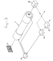
- Figure 3 shows partially in perspective a passive bar code reader comprising focussing means according to the invention.
- the focussing device 1 shown in figure 1 comprises two fixed lenses 2 and 3 and a moveable lens 4.
- the fixed lenses 2 and 3 are mounted in a tubular body 5 by means of retaining elements 6 and 7.
- the moveable lens 4 is mounted in a ring-shaped retainer 8.
- the retainer 8 which is preferably made of a magnetizable or (ferro-) magnetic material, is slidably fitted in the tubular body 5. In order to avoid adhesion between the retainer 8 and the body 5, the latter is preferably made of a non-magnetic material.
- the coils 9 and 10, accommodated in coil holders 11 and 12, are mounted on the exterior of the tubular body 5. As shown in figure 1, the coils 9 and 10 are located near the ends of the tubular body 5, i.e. in the vicinity of the fixed lenses 2 and 3 respectively.
- the lenses 2 and 3 are both positive, single lenses, while the lens 4 is a negative, single lens. It is, however, possible for each lens 2, 3 or 4, to be replaced by a set of lenses of the opposite sign (positive or negative), depending on e.g. the need for aberration correction. For some applications, e.g. for focussing a laser beam, one or both of the fixed lenses 2 and 3 may be omitted altogether.
- the lens system according to the invention as shown in figure 1, have a fixed length, i.e. the length of the tubular body 5.
- the moveable lens 4 can travel between the fixed lenses 2 and 3, the range of travel being limited in the preferred embodiment by the retaining element 6 and 7 and the retainer 8.
- This range of travel provides a large variation in the focal length of the focussing means. In fact, a range of travel of approximately 20 mm may provide a focussing range from 50 to 500 mm.
- the movement of the moveable lens 4 is provided by drive means, constituted by the coils 9 and 10 in combination with the retainer 8.
- drive means constituted by the coils 9 and 10 in combination with the retainer 8.
- the coils 9 and 10 When the coils 9 and 10 are energized, a magnetic field is created, which acts on the magnetic or magnetizable retainer 8, causing the retainer 8 and the lens 4 to move.
- either one or both of the coils 9 and 10 can be energized, using an alternating or a direct current. If the intended range of travel is relatively short, one of the coils 9 or 10 may be omitted. The remaining coil may not be located near one of the ends of the body 5, but for example halfway between the ends.
- the moveable lens 4 is a thin lens having a relatively small mass, the retainer 8 being made as a relatively thin ring.
- the inertia can be further reduced by employing a moveable lens made of plastic or the like.
- the embodiment shown in figure 1, comprising two fixed lenses (or sets of lenses) and one moveable lens offers the advantage that the amount of travel required by the moveable lens to obtain a certain change in focal length may generally be smaller than would be required for a device having only one fixed lens (or set of lenses).
- the overall length of the focussing device does not change.
- the focussing means according to the invention do therefore provide a compact and fast focussing device, enabling the bar code in a relatively large range of distances to be imaged perfectly with a relatively large aperture.
- the focussing device according to the invention with two moveable lenses or sets of lenses, possibly in combination with more than two coils, say three or four coils. This complicates, however, control of the movement of the moveable parts of the device, making more complex excitation current supply means necessary.
- an active bar code reader comprises a laser source 20, such as a diode laser, for producing a laser beam.
- the laser beam is focussed by the focussing means 1, as shown in figure 1, and is subsequently reflected by a small mirror 21 towards the scanning means 22.
- the light scattered by the bar code C is in turn reflected by the polygon 23 in the direction of a lens (or set of lenses) 25 and is focussed by the lens 25 on a sensor 26.
- the mirror 21 should be small enough to enable the bulk of the reflective light to reach the lens 25.
- the sensor 26 produces a signal representative of the bar code, which signal is fed to appriopriate processing means (not shown).
- the bar code reader further comprises supply means 27 for supplying an electrical excitation current to the coils of the focussing means 1.
- the supply means 27 provide a periodical excitation current, causing a periodical movement of the moveable lens. This results in a periodical change in the focal length of the bar code reader. In this way, at some point of time the laser beam will be focussed on the bar code C irrespective of the distance of the code to the reader, provided that the code is within the reader's working range.
- a passive bar code reader comprises focussing means 1 for focussing light scattered by a bar code C on the sensor means 30.
- the sensor means 30 preferably contain an array of CCD-elements (not shown).
- Supply means 27 supply an excitation current to the coils of the focussing means 1 in order to move the moveable lens (not shown) and thus to change the focal length of the focussing means 1.
- the supply means 27 are controlled by control means 31.
- the control means 31 may comprise an ultrasonic or optic range finder for measuring the distance between the bar code and the reader in order to adjust the focussing means 1 accordingly.
- the control means 31 may also comprise contrast measurement means, in which case output signals from the sensor means 30 are fed to the control means 31.
- These sensor output signals are used by the contrast measurement means to determine the contrast between the dark and light areas of the bar code as imaged by the focussing means 1 on the photosensitive array of the sensor means 30.
- the contrast measurement means produce a control signal in response to the measured contrast in order to adjust the focussing means 1.
- the control means 31 may also provide a control signal to an optional gate 32 so as to only pass sensor output signals to subsequent signal processing means (not shown) if the bar code is properly imaged on the photosensitive array of the sensor means 30.
- a periodic signal can be used to produce a periodical movement of the moveable lens (or set of lenses).
- Decoding of the sensor output signals may be performed continuously, the decoding being successful when the bar code is focussed on the sensor array.
Landscapes
- Physics & Mathematics (AREA)
- Engineering & Computer Science (AREA)
- Electromagnetism (AREA)
- Artificial Intelligence (AREA)
- Toxicology (AREA)
- General Health & Medical Sciences (AREA)
- Health & Medical Sciences (AREA)
- Computer Vision & Pattern Recognition (AREA)
- General Physics & Mathematics (AREA)
- Theoretical Computer Science (AREA)
- Focusing (AREA)
- Feeding And Guiding Record Carriers (AREA)
- Mechanical Optical Scanning Systems (AREA)
Claims (13)
- Linsensystem mit Linsenantriebseinrichtungen für einen Strichcodeleser, wobei das Linsensystem (2, 3, 4) mindestens eine Linse oder einen Linsensatz (4) aufweist, die in der Richtung ihrer optischen Achse beweglich ist, und die Antriebseinrichtungen (8, 9, 10) mindestens eine Spule (9, 10) und ein magnetisches Element (8) aufweisen, dadurch gekennzeichnet, daß die mindestens eine bewegliche Linse oder der Linsensatz (4) an dem magnetischen Element (8) befestigt ist, wobei das magnetische Element (8) in einem Halteelement (5) verschiebbar angeordnet ist, und daß die mindestens eine Spule (9, 10) bezüglich des Halteelements (5) befestigt ist.
- Linsensystem nach Anspruch 1, wobei Spulen (9, 10) auf der Außenseite des Halteelements (5) in der Nähe des jeweiligen Endes angeordnet sind.
- Linsensystem nach Anspruch 1 oder 2, wobei das Linsensystem mindestens zwei feststehende Linsen oder Linsensätze (2, 3) aufweist, wobei die mindestens eine bewegliche Linse oder der Linsensatz (4) zwischen zwei feststehenden Linsen oder Linsensätzen (2, 3) beweglich angeordnet ist.
- Linsensystem nach Anspruch 3, wobei die feststehenden Linsen oder Linsensätze (2, 3) in dem Halteelement (5) in der Nähe seiner Enden befestigt sind.
- Linsensystem nach einem der vorstehenden Ansprüche, wobei das Halteelement (5) im wesentlichen rohrförmig ist.
- Linsensystem nach Anspruch 5, wobei das magnetische Element (8) einen magnetischen Ring aufweist, der in das Halteelement (5) verschiebbar eingepaßt ist.
- Strichcodeleser mit einem Linsensystem nach einem der vorstehenden Ansprüche, gekennzeichnet durch eine Zufuhreinrichtung (27), um einen Erregerstrom, der periodisch ist oder der sich als Antwort auf ein Steuersignal ändert, der Antriebseinrichtung zuzuführen.
- Strichcodeleser nach Anspruch 7, wobei das Steuersignal durch einen optischen und/oder Ultraschallabstandsmesser oder eine Kontrastmeßeinrichtung (31) erzeugt wird.
- Strichcodeleser nach Anspruch 7 oder 8, der ferner eine Laserquelle (20) zum Erzeugen eines Laserstrahls aufweist, wobei die Fokussiereinrichtung (1) zum Fokussieren des Laserstrahls angeordnet ist.
- Strichcodeleser nach Anspruch 9, der ferner eine optische Abtasteinrichtung (22) zum Abtasten eines Strichcodes (C) aufweist, wobei die optische Abtasteinrichtung ein drehbares Polygon (23) mit reflektierenden Seiten aufweist.
- Strichcodeleser nach Anspruch 7 oder 8, wobei das Linsensystem so angeordnet ist, daß von einem Strichcode (C) gestreutes Licht auf eine Sensoreinrichtung (30) fokussiert wird.
- Strichcodeleser nach Anspruch 11, der ferner eine Ausblendeeinrichtung (32) aufweist, um Signale wahlweise durchzulassen, die von der Sensoreinrichtung (30) ausgegeben werden, wobei das Durchlassen von Steuersignalen abhängig ist, die von einem Abstandsmesser und/oder einer Kontrastmeßeinrichtung (31) erzeugt werden.
- Strichcodeleser nach Anspruch 12, wobei die von der Sensoreinrichtung (30) erzeugten Signale nur durchgelassen werden, wenn das von einem Strichcode (C) gestreute Licht im wesentlichen auf die Sensoreinrichtung (30) fokussiert wird.
Priority Applications (3)
| Application Number | Priority Date | Filing Date | Title |
|---|---|---|---|
| EP91201153A EP0521196B1 (de) | 1991-05-13 | 1991-05-13 | Fokussiereinrichtung für Strichkodeleser |
| DE69119069T DE69119069T2 (de) | 1991-05-13 | 1991-05-13 | Fokussiereinrichtung für Strichkodeleser |
| US07/882,442 US5387786A (en) | 1991-05-13 | 1992-05-12 | Focussing device for a bar code reader |
Applications Claiming Priority (1)
| Application Number | Priority Date | Filing Date | Title |
|---|---|---|---|
| EP91201153A EP0521196B1 (de) | 1991-05-13 | 1991-05-13 | Fokussiereinrichtung für Strichkodeleser |
Publications (2)
| Publication Number | Publication Date |
|---|---|
| EP0521196A1 EP0521196A1 (de) | 1993-01-07 |
| EP0521196B1 true EP0521196B1 (de) | 1996-04-24 |
Family
ID=8207654
Family Applications (1)
| Application Number | Title | Priority Date | Filing Date |
|---|---|---|---|
| EP91201153A Expired - Lifetime EP0521196B1 (de) | 1991-05-13 | 1991-05-13 | Fokussiereinrichtung für Strichkodeleser |
Country Status (3)
| Country | Link |
|---|---|
| US (1) | US5387786A (de) |
| EP (1) | EP0521196B1 (de) |
| DE (1) | DE69119069T2 (de) |
Families Citing this family (11)
| Publication number | Priority date | Publication date | Assignee | Title |
|---|---|---|---|---|
| US7387253B1 (en) * | 1996-09-03 | 2008-06-17 | Hand Held Products, Inc. | Optical reader system comprising local host processor and optical reader |
| DE29502016U1 (de) * | 1995-02-08 | 1995-03-30 | Linotype-Hell Ag, Werk Kiel, 24107 Kiel | Optoelektronisches Aufzeichnungsorgan |
| EP0885426B1 (de) * | 1996-03-07 | 2001-09-26 | Accu-Sort Systems, Inc. | Dynamisches fokussierungsgeraet fuer optische abbildungssysteme |
| US5988506A (en) * | 1996-07-16 | 1999-11-23 | Galore Scantec Ltd. | System and method for reading and decoding two dimensional codes of high density |
| SG105446A1 (en) * | 1996-09-21 | 2004-08-27 | Oak Technology Inc | Loading mechanism with linear gear bar for an optical disc drive |
| WO1998050814A1 (en) * | 1997-05-05 | 1998-11-12 | Roustaei Alexander R | Optical scanner and image reader for reading images and decoding optical information including one and two dimensional symbologies at variable depth of field |
| US6066857A (en) * | 1998-09-11 | 2000-05-23 | Robotic Vision Systems, Inc. | Variable focus optical system |
| US6098887A (en) * | 1998-09-11 | 2000-08-08 | Robotic Vision Systems, Inc. | Optical focusing device and method |
| US6603136B1 (en) * | 1999-10-15 | 2003-08-05 | Videojet Systems International | Laser marker focal length setting device |
| US20080277480A1 (en) * | 2007-05-10 | 2008-11-13 | Serge Thuries | Temperature compensated auto focus control for a microfluidic lens, such as auto focus control for a microfluidic lens of a bar code scanner |
| US20080277477A1 (en) * | 2007-05-10 | 2008-11-13 | Serge Thuries | Dynamic focus calibration, such as dynamic focus calibration using an open-loop system in a bar code scanner |
Family Cites Families (22)
| Publication number | Priority date | Publication date | Assignee | Title |
|---|---|---|---|---|
| FR2251876B1 (de) * | 1973-11-16 | 1977-09-23 | Thomson Brandt | |
| US4161756A (en) * | 1976-03-19 | 1979-07-17 | Jos. Schneider & Co. Optische Werke | Control system for varifocal objective |
| JPS5330223A (en) * | 1976-09-01 | 1978-03-22 | Nippon Denso Co Ltd | Automaitc code reading unit |
| JPS5831872A (ja) * | 1981-08-19 | 1983-02-24 | Sumitomo Heavy Ind Ltd | 光ファイバ−式キヤプタイヤケ−ブル巻取装置を有した移動機械 |
| JPS5889782A (ja) * | 1981-11-24 | 1983-05-28 | Japan Storage Battery Co Ltd | 密閉形鉛蓄電池 |
| IT1150787B (it) * | 1982-04-06 | 1986-12-17 | Ages Spa | Lettore ottico per codici a barre |
| US4450350A (en) * | 1982-06-28 | 1984-05-22 | Ncr Corporation | Low speed laser scanning apparatus |
| US4639084A (en) * | 1984-01-10 | 1987-01-27 | Canon Kabushiki Kaisha | Lens barrel in which motor capable of selecting stepping drive or brushless drive is provided |
| US4679905A (en) * | 1985-08-02 | 1987-07-14 | Bell & Howell Company | Linear adjustment apparatus |
| US4763987A (en) * | 1985-11-20 | 1988-08-16 | Minolta Camera Kabushiki Kaisha | Lens barrel |
| US4820911A (en) * | 1986-07-11 | 1989-04-11 | Photographic Sciences Corporation | Apparatus for scanning and reading bar codes |
| US4877949A (en) * | 1986-08-08 | 1989-10-31 | Norand Corporation | Hand-held instant bar code reader system with automated focus based on distance measurements |
| DE3736288C2 (de) * | 1987-10-27 | 1994-11-24 | Leuze Electronic Gmbh & Co | Verfahren zum Lesen und Dekodieren von auf der polierten Oberfläche von Halbleiterscheiben angebrachten Strichkodierungen |
| US4905031A (en) * | 1987-12-14 | 1990-02-27 | Eastman Kodak Company | Axial magnetic actuator |
| US5029992A (en) * | 1988-07-26 | 1991-07-09 | Morpheus Lights, Inc. | Motor-controlled lens system |
| US4920255A (en) * | 1988-10-31 | 1990-04-24 | Stephen C. Gabeler | Automatic incremental focusing scanner system |
| US5122644A (en) * | 1988-11-17 | 1992-06-16 | Alps Electric Co., Ltd. | Optical code reading device with autofocussing |
| JPH02146900A (ja) * | 1988-11-28 | 1990-06-06 | Audio Technica Corp | コンデンサマイクロホン用背極板およびその製造方法 |
| JPH02298907A (ja) * | 1989-05-15 | 1990-12-11 | Shinkawa Ltd | 光学系の駆動装置 |
| DE3924269C2 (de) * | 1989-07-22 | 2001-04-05 | Zeiss Carl Fa | Antrieb und Steuerung zur Verschiebung von optischen Gliedern in einem IR-Pankraten |
| US5138497A (en) * | 1991-03-15 | 1992-08-11 | Eastman Kodak Company | High speed focusing lens assembly |
| US5192856A (en) * | 1990-11-19 | 1993-03-09 | An Con Genetics, Inc. | Auto focusing bar code reader |
-
1991
- 1991-05-13 DE DE69119069T patent/DE69119069T2/de not_active Expired - Fee Related
- 1991-05-13 EP EP91201153A patent/EP0521196B1/de not_active Expired - Lifetime
-
1992
- 1992-05-12 US US07/882,442 patent/US5387786A/en not_active Expired - Fee Related
Also Published As
| Publication number | Publication date |
|---|---|
| US5387786A (en) | 1995-02-07 |
| DE69119069D1 (de) | 1996-05-30 |
| EP0521196A1 (de) | 1993-01-07 |
| DE69119069T2 (de) | 1996-12-12 |
Similar Documents
| Publication | Publication Date | Title |
|---|---|---|
| US5979760A (en) | Scanner with linear actuator based lens positioning system | |
| EP0521196B1 (de) | Fokussiereinrichtung für Strichkodeleser | |
| US5559319A (en) | Oscillation bar code reader | |
| CN112014827B (zh) | 物体检测装置 | |
| US5198648A (en) | Code sensor with multi-faceted reflector for sensing plural image distances | |
| US5302812A (en) | Laser scanning device with automatic range and spot size adjustment | |
| EP0776511B1 (de) | Entzerrer für optische wege | |
| JP2006518861A (ja) | 小型自動合焦圧電アクチュエータシステム | |
| EP0786734B1 (de) | Abtaster | |
| US5171983A (en) | Relative position transducer for oscillating and scanning a read head over a coded track region | |
| US5177343A (en) | Symbol reader using differentiating circuit for light beam focusing | |
| KR950006413B1 (ko) | 광 주사시스템 | |
| GB2109583A (en) | Optical head devices for generating and controlling a light beam | |
| EP0757270B1 (de) | Autofokusvorrichtung | |
| US7448549B2 (en) | Optical information reader and method of reading optical information | |
| WO2010104510A1 (en) | Variable focus optical system | |
| JPH04321370A (ja) | 走査光学装置 | |
| US5517362A (en) | Optical pickup device | |
| JPH03217806A (ja) | レンズ位置検出装置 | |
| JP3101397B2 (ja) | 光走査装置 | |
| KR200208636Y1 (ko) | 3차원영상측정시스템 | |
| WO2024128290A1 (ja) | 傾斜検出装置及び傾斜検出方法 | |
| JPS63163310A (ja) | オ−トフオ−カス装置とそのレンズ駆動機構 | |
| JPH0293559A (ja) | レーザービームプリンタ装置 | |
| JPH03214279A (ja) | 記号読取装置 |
Legal Events
| Date | Code | Title | Description |
|---|---|---|---|
| PUAI | Public reference made under article 153(3) epc to a published international application that has entered the european phase |
Free format text: ORIGINAL CODE: 0009012 |
|
| 17P | Request for examination filed |
Effective date: 19920519 |
|
| AK | Designated contracting states |
Kind code of ref document: A1 Designated state(s): AT BE CH DE DK ES FR GB GR IT LI LU NL SE |
|
| 17Q | First examination report despatched |
Effective date: 19950726 |
|
| GRAA | (expected) grant |
Free format text: ORIGINAL CODE: 0009210 |
|
| RBV | Designated contracting states (corrected) |
Designated state(s): DE FR GB NL |
|
| AK | Designated contracting states |
Kind code of ref document: B1 Designated state(s): DE FR GB NL |
|
| REF | Corresponds to: |
Ref document number: 69119069 Country of ref document: DE Date of ref document: 19960530 |
|
| PGFP | Annual fee paid to national office [announced via postgrant information from national office to epo] |
Ref country code: NL Payment date: 19960531 Year of fee payment: 6 |
|
| ET | Fr: translation filed | ||
| PLBE | No opposition filed within time limit |
Free format text: ORIGINAL CODE: 0009261 |
|
| STAA | Information on the status of an ep patent application or granted ep patent |
Free format text: STATUS: NO OPPOSITION FILED WITHIN TIME LIMIT |
|
| 26N | No opposition filed | ||
| PGFP | Annual fee paid to national office [announced via postgrant information from national office to epo] |
Ref country code: GB Payment date: 19970506 Year of fee payment: 7 |
|
| PGFP | Annual fee paid to national office [announced via postgrant information from national office to epo] |
Ref country code: FR Payment date: 19970513 Year of fee payment: 7 |
|
| PGFP | Annual fee paid to national office [announced via postgrant information from national office to epo] |
Ref country code: DE Payment date: 19970516 Year of fee payment: 7 |
|
| PG25 | Lapsed in a contracting state [announced via postgrant information from national office to epo] |
Ref country code: NL Effective date: 19971201 |
|
| NLV4 | Nl: lapsed or anulled due to non-payment of the annual fee |
Effective date: 19971201 |
|
| PG25 | Lapsed in a contracting state [announced via postgrant information from national office to epo] |
Ref country code: GB Free format text: LAPSE BECAUSE OF NON-PAYMENT OF DUE FEES Effective date: 19980513 |
|
| PG25 | Lapsed in a contracting state [announced via postgrant information from national office to epo] |
Ref country code: FR Free format text: LAPSE BECAUSE OF NON-PAYMENT OF DUE FEES Effective date: 19980531 |
|
| GBPC | Gb: european patent ceased through non-payment of renewal fee |
Effective date: 19980513 |
|
| PG25 | Lapsed in a contracting state [announced via postgrant information from national office to epo] |
Ref country code: DE Free format text: LAPSE BECAUSE OF NON-PAYMENT OF DUE FEES Effective date: 19990302 |
|
| REG | Reference to a national code |
Ref country code: FR Ref legal event code: ST |