EP0521322A2 - Aus zwei Halbschalen bestehndes Rohr - Google Patents
Aus zwei Halbschalen bestehndes Rohr Download PDFInfo
- Publication number
- EP0521322A2 EP0521322A2 EP92109889A EP92109889A EP0521322A2 EP 0521322 A2 EP0521322 A2 EP 0521322A2 EP 92109889 A EP92109889 A EP 92109889A EP 92109889 A EP92109889 A EP 92109889A EP 0521322 A2 EP0521322 A2 EP 0521322A2
- Authority
- EP
- European Patent Office
- Prior art keywords
- sealing element
- groove
- shells
- shell
- pipe according
- Prior art date
- Legal status (The legal status is an assumption and is not a legal conclusion. Google has not performed a legal analysis and makes no representation as to the accuracy of the status listed.)
- Granted
Links
Images

Classifications
-
- H—ELECTRICITY
- H02—GENERATION; CONVERSION OR DISTRIBUTION OF ELECTRIC POWER
- H02G—INSTALLATION OF ELECTRIC CABLES OR LINES, OR OF COMBINED OPTICAL AND ELECTRIC CABLES OR LINES
- H02G9/00—Installations of electric cables or lines in or on the ground or water
- H02G9/06—Installations of electric cables or lines in or on the ground or water in underground tubes or conduits; Tubes or conduits therefor
- H02G9/065—Longitudinally split tubes or conduits therefor
Definitions
- Pipe consisting of two half-shells, in which a sealant is provided between the contact surfaces of the two half-shells in a groove in the end face of one half-shell, into which a barbed spring on the end face of the other half-shell engages.
- Such consisting of two half-shells tubes, which are used as repair pieces of protective tubes for cables or the like.
- DE PS 33 02 339 are sealed by each half-shell on one long side having an undercut groove-shaped chamber with a destructible cover, within a sealing element runs in the chamber formed in this way and a barb-shaped spring is present on the opposite long side of the half-shell, which spring is pressed into the groove-shaped chamber of the respective other half-shell and is thus locked in a sealing manner with the latter.
- the pipe itself After covering with earth, the pipe itself is at rest for long periods of time. However, if such a pipe is relocated or damaged, for example during excavation work, etc., the repair piece consisting of two half-shells must be used. In order to be able to cover such a damaged pipe again with cables, it must either be dug out, which is very complex, or the cable or cables must be subsequently pulled into the pipe covered with soil.
- a plug is inserted into the pipe end to which the cable is attached. Then the end of the pipe is closed and air is injected under pressure up to approx. 10 / bar, whereby the plug together with the attached cable is blown through the pipe.
- This measure has the consequence that the tube expands considerably and the spring located in the groove of the other half-shell can stand out from the sealing element, so that the air under pressure inside the tube can escape from the same and the plug with the Cable gets stuck in the pipe.
- the invention seeks to remedy this.
- the invention as characterized in the claims, solves the problem of creating a tube consisting of two half-shells, which remains gas and watertight even when subjected to a higher internal pressure.
- the advantages achieved by the invention are, in particular, the tightness of the connection of the two half-shells of the pipe itself under a tensile stress on the connection caused by expansion of the pipe wall when the internal pressure in the pipe increases, and furthermore the simple handling and economical production of such a pipe connection.
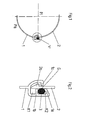
- Fig. 1 shows the representation of a divided, consisting of two half-shells protective tube, in which there is a tight connection between the two half-shells in the area "X".
- the pressure prevailing in the interior of the tube 1, 2 is designated by Pi and the external pressure by Pa.
- the pressure Pi is greater than Pa.
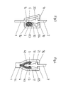
- Fig. 2 shows in the area "X" of Fig. 1, the lower half-shell of the tube, which is designated 1 and the upper half with 2.
- the lower half-shell 1 opens into a groove ", the wall of which is designated 1 and forms two chambers K1 and K2. These chambers are separated from one another by a web 1b.
- the chamber K1 serves to receive the barb-shaped extension 2a of the upper half-shell 2, while the chamber K2 serves to receive a sealing element 3 or the like.
- the left extension of the wall 1 moves outwards and springs back after penetration of the barb-shaped extension, so that the latter with some play This play is necessary in order to absorb a certain expansion of the tube when pressure is applied.
- the back of the barb-shaped extension 2a slides along the outer flank of the sealing element 3, which is located in the chamber K2 and is slightly compressed when the barb-shaped extension 2a is pressed in.
- the two half-shells 1, 2 expand, so that the barb-shaped extension 2a performs an upward movement until it hits the catch.
- the sealing effect of the sealing element 3 is fully retained, since it is a sliding movement of the sliding surface G of the spring 2 perpendicular to the force effect of the deformed sealing element 3 and not, like half-shell pipes according to. the prior art, the barb-shaped extension 2a can stand out from the sealing element.
- the sealing element 3 is located outside the lines of force that still run vertically within the half-shell 2 via the barb-shaped extension 2a into the wall shell 1.
- FIG. 3 An embodiment variant of FIG. 2 is shown in FIG. 3.
- the barb-shaped extension 2b of the half-shell 2 is double-sided and latches with the extensions 1 of the groove wall 1c.
- An extension 1 extends into the interior of the groove, so that two chambers K3 for the sealing element 3 and K4 are formed for the barb-shaped extension 2b.
- the function corresponds to that of FIG. 2.
- FIG. 4 Another embodiment variant is shown in FIG. 4.
- a symmetrical, approximately tulip-shaped groove is formed from the end face of the wall of the half-shell 1, which is designated 1f and forms the chamber K5.
- This chamber K5 serves both to receive the barb-shaped extension 2c and the sealing element.
- the sealing element 4 is of a cup-shaped cross section and has at the upper end of the wall 4a an indentation 4b with an opening into which the barb-shaped extension 2c is immersed and, if appropriate, a stem 4c which is inserted into a groove in the bottom of the chamber K5.
- the function also corresponds to that of FIG. 2, only with the difference that the barb-shaped extension 2d in this case comprises on both sides, that is to say is sealed on both sides.
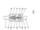
- FIG. 5 shows a further embodiment variant of the invention, in which the groove on the end face of the half-shell 1 is divided into two chambers K6 and K7 by two opposing webs 1 i.
- a sealing element 5 is located with its lower part in the chamber K6, while its web-like extension, which can also be profiled, protrudes through the gap between the two webs 1 i into the upper chamber K7, where it is next to the barb-shaped extension 2d and 2e , which is slotted approximately in the middle, protrudes.
- the groove can be closed at the factory, for example, to protect it from contamination in a known manner by means of a destructible cover (A) (FIG. 6).
- the sealing element 6 can be provided with sections of different Shore hardness or with one or more reinforcements 6a.
- the direction of movement of the sliding surface G is always perpendicular to the force effect of the deformed sealing element 6.
Landscapes
- Laying Of Electric Cables Or Lines Outside (AREA)
- Rigid Pipes And Flexible Pipes (AREA)
- Materials For Medical Uses (AREA)
- Paper (AREA)
- Electric Cable Installation (AREA)
- Infusion, Injection, And Reservoir Apparatuses (AREA)
- Structure And Mechanism Of Cameras (AREA)
- Instruments For Viewing The Inside Of Hollow Bodies (AREA)
- Protection Of Pipes Against Damage, Friction, And Corrosion (AREA)
- Quick-Acting Or Multi-Walled Pipe Joints (AREA)
Abstract
Description
- Aus zwei Halbschalen bestehendes Rohr, bei dem zwischen den Berührungsflächen der beiden Halbschalen in einer Nut der Stirnseite der einen Halbschale ein Dichtmittel vorgesehen ist, in das eine widerhakenförmige Feder der Stirnseite der anderen Halbschale eingreift.
- Derartige, aus zwei Halbschalen bestehende Rohre, die als Reparaturstücke von Schutzrohren für Kabel oder dgl. eingesetzt werden, werden wie aus der DE PS 33 02 339 hervorgeht abgedichtet, indem jede Halbschale auf einer Längsseite eine hinterschnittene nutförmige Kammer mit einer zerstörbaren Abdeckung besitzt, innerhalb der so gebildeten Kammer ein Dichtelement verläuft und auf der gegenüberliegenden Längsseite der Halbschale, eine widerhakenförmige Feder vorhanden ist, die in die nutförmige Kammer der jeweiligen anderen Halbschale eingedrückt und somit mit dieser dichtend verrastet ist.
- Nach der Abdeckung mit Erde ist das Rohr an sich für lange Zeitabschnitte in Ruhe. Falls ein solches Rohr jedoch neubelegt oder auch beschädigt wird, beispw. bei Baggerarbeiten etc., muß das aus zwei Halbschalen bestehende Reparaturstück eingesetzt werden. Um nun ein solches beschädigtes Rohr wieder mit Kabeln belegen zu können, muß es entweder ausgegraben, was sehr aufwendig ist, oder aber, das bzw. die Kabel in das mit Erdreich überdeckte Rohr nachträglich eingezogen werden. Dazu wird ein Stopfen in das Rohrende eingeführt, an dem das Kabel befestigt ist. Anschließend wird das Rohrende verschlossen und Luft unter Druck bis zu ca. 10/bar eingepreßt, wodurch der Stopfen mitsamt dem befestigten Kabel durch das Rohr geblasen wird. Diese Maßnahme hat zur Folge, daß das Rohr sich erheblich dehnt und die in der Nut der anderen Halbschale befindliche Feder, sich von dem Dichtelement abheben kann, so daß die unter Druck stehende Luft im Inneren des Rohres aus demselben entweichen kann und der Stopfen mit dem Kabel im Rohr hängenbleibt.
- Hier will die Erfindung Abhilfe schaffen. Die Erfindung, wie sie in den Ansprüchen gekennzeichnet ist, löst die Aufgabe, ein aus zwei Halbschalen bestehendes Rohr zu schaffen, das auch bei der Beaufschlagung mit höherem Innendruck, gas- und wasserdicht bleibt.
- Die mit der Erfindung erzielten Vorteile liegen insbesondere in der Dichtheit der Verbindung der beiden Halbschalen des Rohres selbst unter einer durch Dehnung der Rohrwandung hervorgerufenen Zugbeanspruchung der Verbindung bei Anstieg des Innendruckes im Rohr und weiterhin in der einfachen Handhabung und wirtschaftlichen Herstellung einer solchen Rohrverbindung.
- Die Erfindung ist anhand der nachstehend aufgeführten Ausführungsbeispiele erläutert:
- Es zeigt:
- Fig. 1 Ein aus zwei Halbschalen zusammengesetztes Rohr im Schnitt,
- Fig. 2 den Teilbereich "X" der Fig. 2 im Schnitt,
- Fig. 3-5 Ausführungsvarianten der Fig. 2
- Fig. 6-7 weitere Ausführungsvarianten.
- Die Fig. 1 läßt die Darstellung eines geteilten, aus zwei Halbschalen bestehenden Schutzrohres erkennen, bei dem in dem Bereich "X" eine dichte Verbindung zwischen den beiden Halbschalen vorhanden ist. Der in dem im Inneren des Rohres 1,2 herrschende Druck ist mit Pi und der äußere Druck mit Pa bezeichnet. Der Druck Pi sei größer als Pa.
- Die Fig. 2 zeigt in dem Bereich "X" der Fig. 1 die untere Halbschale des Rohres, die mit 1 und die obere mit 2 bezeichnet ist. Die untere Halbschale 1 mündet in eine Nut", deren Wandung mit 1 bezeichnet ist und zwei Kammern K1 und K2 bildet. Diese Kammern sind durch einen Steg 1 b voneinander getrennt. Die Kammer K1 dient zur Aufnahme des widerhakenförmigen Fortsatzes 2a der oberen Halbschale 2, während die Kammer K2 zur Aufnahme eines Dichtelementes 3 oder dgl. dient. Beim Eindrücken der oberen Halbschale 2 in die Kammer K1 bewegt sich der linke Fortsatz der Wandung 1 nach außen und federt nach Durchdringen des widerhakenförmigen Fortsatzes wieder zurück, so daß letzterer mit etwas Spiel verrastet ist. Dieses Spiel ist notwendig, um eine gewisse Dehnung des Rohres bei Druckbeaufschlagung aufzufangen.
- Die Rückseite des widerhakenförmigen Fortsatzes 2a gleitet dabei an der äußeren Flanke des Dichtelementes 3 entlang, die sich in der Kammer K2 befindet und beim Eindrücken des widerhakenförmigen Fortsatzes 2a leicht komprimiert wird. Bei Erhöhung des Druckes Pi werden sich die beiden Halbschalen 1,2 dehnen, so daß der widerhakenförmige Fortsatz 2a eine Aufwärtsbewegung durchführt, bis er an die Rast stößt. Dabei bleibt die Dichtwirkung des Dichtelementes 3 voll erhalten, da es sich dabei um eine vorbeigleitende Bewegung der Gleitfläche G der Feder 2 senkrecht zur Kraftwirkung des verformten Dichtelementes 3 handelt und nicht, wie Halbschalenrohre gem. dem Stand der Technik, der widerhakenförmige Fortsatz 2a sich von der Dichtelement abheben kann. Das Dichtelement 3 befindet sich dabei außerhalb der Kraftlinien, die senkrecht noch innerhalb der Halbschale 2 über den widerhakenförmigen Fortsatz 2a in die Wandschale 1 verlaufen.
- Eine Ausführungsvariante der Fig. 2 zeigt Fig. 3. Dort ist der widerhakenförmige Fortsatz 2b der Halbschale 2 doppelseitig ausgeführt und verrastet mit den Fortsätzen 1 der Nutwandung 1 c. Ein Fortsatz 1 erstreckt sich in das Innere der Nut, so daß zwei Kammern K3 für das Dichtelement 3 und K4 für den widerhakenförmigen Fortsatz 2b gebildet werden. Die Funktion entspricht der der Fig. 2.
- Eine weitere Ausführungsvariante ist in Fig. 4 gezeigt. Dabei ist eine symmetrisch, im Schnitt etwa tulpenförmig ausgebildete Nut, aus der Stirnseite der Wand der Halbschale 1 geformt, die mit 1f bezeichnet ist und die Kammer K5 bildet. Diese Kammer K5 dient sowohl zur Aufnahme des widerhakenförmigen Fortsatzes 2c als auch des Dichtelementes.
- Die Dichtelement 4 ist im Schnitt kelchförmig ausgebildet und besitzt am oberen Ende der Wandung 4a eine Einbuchtung 4b mit einer Öffnung, in die der widerhakenförmige Fortsatz 2c eintaucht und ggf. einen Stiel 4c, der in eine Rille des Bodens der Kammer K5 eingesetzt ist. Die Funktion entspricht ebenfalls der der Fig. 2, nur mit dem Unterschied, daß der widerhakenförmige Fortsatz 2d hierbei beidseitig umfaßt, also doppelseitig abgedichtet ist.
- Fig. 5 zeigt eine weitere Ausführungsvariante der Erfindung, bei der die Nut auf der Stirnseite der Halbschale 1 durch zwei sich gegenüberliegende Stege 1 i in zwei Kammern K6 und K7 geteilt ist. Ein Dichtelement 5 befindet sich mit seinem unteren Teil in der Kammer K6, während sein stegartiger Fortsatz, der zusätzlich profiliert sein kann, durch den Spalt zwischen den beiden Stegen 1 i in die obere Kammer K7 ragt, wo er neben den widerhakenförmigen Fortsatz 2d und 2e, der etwa in der Mitte geschlitzt ist, ragt.
- Die Nut kann beispielsweise zum Schutz vor Verschmutzung in bekannter Weise mittels einer zerstörbaren Abdeckung (A) werkseitig verschlossen sein (Fig. 6).
- Das Dichtelement 6 kann, wie in den Abbildungen 6 und 7 dargestellt, aus Abschnitten unterschiedlicher Shorehärte oder mit einer oder mehreren Armierungen 6a versehen sein. Auch bei dieser Ausführungsvariante ist die Bewegungsrichtung der Gleitfläche G stets senkrecht zur Kraftwirkung des verformten Dichtelementes 6.
Claims (9)
Applications Claiming Priority (4)
| Application Number | Priority Date | Filing Date | Title |
|---|---|---|---|
| DE4122193 | 1991-07-04 | ||
| DE4122193 | 1991-07-04 | ||
| DE4218526 | 1992-06-05 | ||
| DE4218526A DE4218526C3 (de) | 1991-07-04 | 1992-06-05 | Aus zwei Halbschalen bestehendes Rohr |
Publications (3)
| Publication Number | Publication Date |
|---|---|
| EP0521322A2 true EP0521322A2 (de) | 1993-01-07 |
| EP0521322A3 EP0521322A3 (en) | 1993-05-26 |
| EP0521322B1 EP0521322B1 (de) | 1995-04-05 |
Family
ID=25905216
Family Applications (1)
| Application Number | Title | Priority Date | Filing Date |
|---|---|---|---|
| EP92109889A Expired - Lifetime EP0521322B1 (de) | 1991-07-04 | 1992-06-12 | Aus zwei Halbschalen bestehndes Rohr |
Country Status (11)
| Country | Link |
|---|---|
| EP (1) | EP0521322B1 (de) |
| AT (1) | ATE120892T1 (de) |
| CZ (1) | CZ282818B6 (de) |
| DE (1) | DE4218526C3 (de) |
| DK (1) | DK0521322T3 (de) |
| ES (1) | ES2073819T3 (de) |
| HR (1) | HRP920200B1 (de) |
| HU (1) | HU215756B (de) |
| RU (1) | RU2068522C1 (de) |
| SI (1) | SI9200128B (de) |
| SK (1) | SK278727B6 (de) |
Cited By (3)
| Publication number | Priority date | Publication date | Assignee | Title |
|---|---|---|---|---|
| EP0865134A3 (de) * | 1997-03-12 | 1999-09-22 | gabo Systemtechnik GmbH | Aus zwei Halbschalen bestehendes Reparaturstück |
| CN101752820A (zh) * | 2010-02-24 | 2010-06-23 | 周建华 | 地埋线缆保护套 |
| USD900983S1 (en) | 2019-02-20 | 2020-11-03 | Ipex Technologies Inc. | Secondary double containment pipe |
Families Citing this family (2)
| Publication number | Priority date | Publication date | Assignee | Title |
|---|---|---|---|---|
| DE29715572U1 (de) * | 1997-09-01 | 1999-01-07 | Filterwerk Mann & Hummel Gmbh, 71638 Ludwigsburg | Rohr, bestehend aus aneinandergesetzten Schalen |
| DE102013001409B4 (de) | 2013-01-28 | 2014-12-11 | Gabo Systemtechnik Gmbh | Kabelschutzrohr zum Aufnehmen von Kabeln |
Family Cites Families (17)
| Publication number | Priority date | Publication date | Assignee | Title |
|---|---|---|---|---|
| DE656103C (de) * | 1938-01-29 | Christoph Aue | Klammer zum Zusammenhalten von zweiteiligen Kabelkanaelen | |
| DE913600C (de) * | 1952-08-17 | 1954-06-18 | Armco Int Corp | Verbindungsanordnung fuer zusammensetzbare Abflussrohre |
| DE1770845U (de) * | 1958-05-09 | 1958-07-24 | Robert Doerrenhaus Fa | Profilrohr, welches aus zwei schalenfoermigen profilen besteht. |
| DE1604736A1 (de) * | 1966-08-25 | 1971-01-14 | Siemens Ag | Verfahren zum Verbinden von Teilen aus Kunststoff |
| US3459234A (en) * | 1967-08-08 | 1969-08-05 | Robert L Richter | Two-piece extruded tubular assembly |
| GB1257732A (de) * | 1968-11-04 | 1971-12-22 | ||
| DE1905299A1 (de) * | 1969-02-04 | 1970-08-06 | Artur Fischer | Spielzeugbaukasten mit Bauelementen |
| DE2131429C2 (de) * | 1971-06-24 | 1973-04-12 | Prix Bauelemente Wieliofsicy & DrexJ, 8919 Schondorf | Rohr, insbesondere lueftungsrohr |
| DE2304852B2 (de) * | 1973-02-01 | 1977-12-15 | Thyssen Plastik Anger KG, 8000 München | Rohrverbindung |
| DE3302339C2 (de) * | 1983-01-25 | 1986-06-12 | Thyssen Plastik Anger KG, 8000 München | Kabelschutzrohr o.dgl. |
| US4640314A (en) * | 1984-07-23 | 1987-02-03 | Kirkhill Rubber Company | Enclosed conduit |
| SU1508969A3 (ru) * | 1985-07-30 | 1989-09-15 | Риб-Лок Интернэшнл Лимитед | Полотно дл изготовлени трубы |
| DE3705683A1 (de) * | 1987-03-23 | 1988-10-06 | Thyssen Polymer Gmbh | Dichtring, vorzugsweise fuer kabelkanalrohre oder dergl. |
| DE3710665A1 (de) * | 1987-03-31 | 1988-10-27 | Meinig Metu System | Stossverbindung zwischen zwei blechkanalabschnitten |
| US4967800A (en) * | 1989-01-23 | 1990-11-06 | American Maplan Corporation | Secondary confinement pipe having segments with interlocking rib and groove joints and coextruded sealant layers #4 |
| DE9001931U1 (de) * | 1990-02-19 | 1990-04-26 | REHAU AG + Co., 95111 Rehau | Längsgeteilte schlauchförmige Umhüllung |
| DE4036759A1 (de) * | 1990-11-17 | 1992-05-21 | Vogelsang Ernst Gmbh Co Kg | Rohrverbinder aus muffe und einsteckteil, insbesondere fuer kunststoffrohre |
-
1992
- 1992-06-05 DE DE4218526A patent/DE4218526C3/de not_active Expired - Lifetime
- 1992-06-12 ES ES92109889T patent/ES2073819T3/es not_active Expired - Lifetime
- 1992-06-12 DK DK92109889.3T patent/DK0521322T3/da active
- 1992-06-12 AT AT92109889T patent/ATE120892T1/de active
- 1992-06-12 EP EP92109889A patent/EP0521322B1/de not_active Expired - Lifetime
- 1992-07-01 SI SI9200128A patent/SI9200128B/sl unknown
- 1992-07-03 RU SU925052079A patent/RU2068522C1/ru active
- 1992-07-03 HU HU9202222A patent/HU215756B/hu unknown
- 1992-07-03 SK SK2098-92A patent/SK278727B6/sk not_active IP Right Cessation
- 1992-07-03 CZ CS922098A patent/CZ282818B6/cs not_active IP Right Cessation
- 1992-07-03 HR HRP4218526.2A patent/HRP920200B1/xx not_active IP Right Cessation
Cited By (4)
| Publication number | Priority date | Publication date | Assignee | Title |
|---|---|---|---|---|
| EP0865134A3 (de) * | 1997-03-12 | 1999-09-22 | gabo Systemtechnik GmbH | Aus zwei Halbschalen bestehendes Reparaturstück |
| CN101752820A (zh) * | 2010-02-24 | 2010-06-23 | 周建华 | 地埋线缆保护套 |
| CN101752820B (zh) * | 2010-02-24 | 2011-08-24 | 周建华 | 地埋线缆保护套 |
| USD900983S1 (en) | 2019-02-20 | 2020-11-03 | Ipex Technologies Inc. | Secondary double containment pipe |
Also Published As
| Publication number | Publication date |
|---|---|
| EP0521322A3 (en) | 1993-05-26 |
| SK278727B6 (sk) | 1998-01-14 |
| EP0521322B1 (de) | 1995-04-05 |
| SK209892A3 (en) | 1993-11-10 |
| CZ282818B6 (cs) | 1997-10-15 |
| HUT64800A (en) | 1994-02-28 |
| HU215756B (hu) | 1999-02-01 |
| HRP920200B1 (en) | 1997-08-31 |
| SI9200128B (en) | 2001-04-30 |
| DE4218526A1 (de) | 1993-02-25 |
| ES2073819T3 (es) | 1995-08-16 |
| DE4218526C3 (de) | 2000-01-05 |
| DE4218526C2 (de) | 1995-05-04 |
| SI9200128A (en) | 1993-03-31 |
| HU9202222D0 (en) | 1992-10-28 |
| RU2068522C1 (ru) | 1996-10-27 |
| HRP920200A2 (hr) | 1994-04-30 |
| ATE120892T1 (de) | 1995-04-15 |
| DK0521322T3 (da) | 1995-08-28 |
| CZ209892A3 (en) | 1993-01-13 |
Similar Documents
| Publication | Publication Date | Title |
|---|---|---|
| DE3644834C1 (de) | Rohrverbinder aus Muffe und Einsteckteil | |
| DE1182483B (de) | Rohrverbindung | |
| DE1425493B2 (de) | Elastische Profildichtung fur Türen | |
| EP3024101A1 (de) | Flexibles schutzrohr | |
| EP0521322B1 (de) | Aus zwei Halbschalen bestehndes Rohr | |
| DE102013108210A1 (de) | Kettenschloss zum Verbinden der Enden von Perlketten | |
| EP1000285A1 (de) | Anordnung zum führen von kabeln oder leitungen | |
| DE3103235A1 (de) | Universalmuffe fuer fernverbindungs- bzw. energiekabel | |
| DE69107151T2 (de) | Verfahren zum Einziehen einer grossen Fernmeldekabellänge in ein Rohr und Vorrichtung zur Durchführung dieses Verfahrens. | |
| DE4308605C2 (de) | Vorrichtung zur Injektion von Behandlungsflüssigkeit in Holz | |
| EP0122924B1 (de) | Injektionsvorrichtung | |
| DE2439100A1 (de) | Rohrverbindungsstueck mit verriegelungsmechanismus | |
| EP1128102B1 (de) | Ventil mit Kupplungselementen | |
| DE102020102583A1 (de) | Leitungsdurchführung | |
| DE9207626U1 (de) | Aus zwei Halbschalen bestehendes Rohr | |
| DE102019213029A1 (de) | Schraubenmuttervorrichtung | |
| DE20115404U1 (de) | Lichtschacht | |
| DE2031629A1 (de) | Verbindungselement für Rohre, Wellen oder dergleichen | |
| DE2937000A1 (de) | Rohruebergangsvorrichtung | |
| DE19838040C2 (de) | Gebäudeanschlußvorrichtung für Versorgungsleitungen | |
| WO2019106169A1 (de) | Gehäuse | |
| DE1207732B (de) | Rohrverbindung | |
| DE867769C (de) | Muffenrohrverbindung | |
| DE915683C (de) | Schieber fuer Reissverschluss | |
| DE29917002U1 (de) | Übergangsstück für den Übergang von einem Metall- auf ein Kunststoffrohr für Gas- und Flüssigkeitsleitungen |
Legal Events
| Date | Code | Title | Description |
|---|---|---|---|
| PUAI | Public reference made under article 153(3) epc to a published international application that has entered the european phase |
Free format text: ORIGINAL CODE: 0009012 |
|
| AK | Designated contracting states |
Kind code of ref document: A2 Designated state(s): AT BE CH DK ES FR GB GR IT LI LU NL SE |
|
| PUAL | Search report despatched |
Free format text: ORIGINAL CODE: 0009013 |
|
| AK | Designated contracting states |
Kind code of ref document: A3 Designated state(s): AT BE CH DK ES FR GB GR IT LI LU NL SE |
|
| 17P | Request for examination filed |
Effective date: 19930611 |
|
| 17Q | First examination report despatched |
Effective date: 19940727 |
|
| GRAA | (expected) grant |
Free format text: ORIGINAL CODE: 0009210 |
|
| AK | Designated contracting states |
Kind code of ref document: B1 Designated state(s): AT BE CH DK ES FR GB GR IT LI LU NL SE |
|
| REF | Corresponds to: |
Ref document number: 120892 Country of ref document: AT Date of ref document: 19950415 Kind code of ref document: T |
|
| ITF | It: translation for a ep patent filed | ||
| ET | Fr: translation filed | ||
| GBT | Gb: translation of ep patent filed (gb section 77(6)(a)/1977) |
Effective date: 19950619 |
|
| REG | Reference to a national code |
Ref country code: ES Ref legal event code: FG2A Ref document number: 2073819 Country of ref document: ES Kind code of ref document: T3 |
|
| REG | Reference to a national code |
Ref country code: DK Ref legal event code: T3 |
|
| REG | Reference to a national code |
Ref country code: GR Ref legal event code: FG4A Free format text: 3016739 |
|
| PLBQ | Unpublished change to opponent data |
Free format text: ORIGINAL CODE: EPIDOS OPPO |
|
| PLBI | Opposition filed |
Free format text: ORIGINAL CODE: 0009260 |
|
| 26 | Opposition filed |
Opponent name: DIPL.-ING. DR. ERNST VOGELSANG GMBH & CO. KG Effective date: 19951222 |
|
| PLBF | Reply of patent proprietor to notice(s) of opposition |
Free format text: ORIGINAL CODE: EPIDOS OBSO |
|
| NLR1 | Nl: opposition has been filed with the epo |
Opponent name: DIPL.-ING. DR. ERNST VOGELSANG GMBH & CO. KG |
|
| PLBF | Reply of patent proprietor to notice(s) of opposition |
Free format text: ORIGINAL CODE: EPIDOS OBSO |
|
| PLBF | Reply of patent proprietor to notice(s) of opposition |
Free format text: ORIGINAL CODE: EPIDOS OBSO |
|
| PLBO | Opposition rejected |
Free format text: ORIGINAL CODE: EPIDOS REJO |
|
| PLBN | Opposition rejected |
Free format text: ORIGINAL CODE: 0009273 |
|
| STAA | Information on the status of an ep patent application or granted ep patent |
Free format text: STATUS: OPPOSITION REJECTED |
|
| 27O | Opposition rejected |
Effective date: 19971026 |
|
| REG | Reference to a national code |
Ref country code: CH Ref legal event code: PUE Owner name: THYSSEN POLYMER GMBH TRANSFER- GABO SYSTEMTECHNIK |
|
| REG | Reference to a national code |
Ref country code: GB Ref legal event code: 732E |
|
| NLR2 | Nl: decision of opposition | ||
| NLS | Nl: assignments of ep-patents |
Owner name: GABO SYSTEMTECHNIK GMBH |
|
| REG | Reference to a national code |
Ref country code: FR Ref legal event code: TP |
|
| REG | Reference to a national code |
Ref country code: FR Ref legal event code: CD |
|
| REG | Reference to a national code |
Ref country code: ES Ref legal event code: PC2A |
|
| REG | Reference to a national code |
Ref country code: GB Ref legal event code: IF02 |
|
| PGFP | Annual fee paid to national office [announced via postgrant information from national office to epo] |
Ref country code: GR Payment date: 20110627 Year of fee payment: 20 Ref country code: LU Payment date: 20110622 Year of fee payment: 20 Ref country code: SE Payment date: 20110622 Year of fee payment: 20 Ref country code: ES Payment date: 20110629 Year of fee payment: 20 Ref country code: FR Payment date: 20110630 Year of fee payment: 20 Ref country code: CH Payment date: 20110623 Year of fee payment: 20 |
|
| PGFP | Annual fee paid to national office [announced via postgrant information from national office to epo] |
Ref country code: AT Payment date: 20110620 Year of fee payment: 20 Ref country code: GB Payment date: 20110621 Year of fee payment: 20 Ref country code: DK Payment date: 20110623 Year of fee payment: 20 Ref country code: NL Payment date: 20110623 Year of fee payment: 20 |
|
| PGFP | Annual fee paid to national office [announced via postgrant information from national office to epo] |
Ref country code: BE Payment date: 20110621 Year of fee payment: 20 |
|
| PGFP | Annual fee paid to national office [announced via postgrant information from national office to epo] |
Ref country code: IT Payment date: 20110627 Year of fee payment: 20 |
|
| REG | Reference to a national code |
Ref country code: NL Ref legal event code: V4 Effective date: 20120612 |
|
| REG | Reference to a national code |
Ref country code: CH Ref legal event code: PL |
|
| BE20 | Be: patent expired |
Owner name: *GABO SYSTEMTECHNIK G.M.B.H. Effective date: 20120612 |
|
| REG | Reference to a national code |
Ref country code: DK Ref legal event code: EUP |
|
| REG | Reference to a national code |
Ref country code: GB Ref legal event code: PE20 Expiry date: 20120611 |
|
| REG | Reference to a national code |
Ref country code: SE Ref legal event code: EUG |
|
| PG25 | Lapsed in a contracting state [announced via postgrant information from national office to epo] |
Ref country code: GB Free format text: LAPSE BECAUSE OF EXPIRATION OF PROTECTION Effective date: 20120611 |
|
| REG | Reference to a national code |
Ref country code: GR Ref legal event code: MA Ref document number: 950401847 Country of ref document: GR Effective date: 20120613 |
|
| REG | Reference to a national code |
Ref country code: AT Ref legal event code: MK07 Ref document number: 120892 Country of ref document: AT Kind code of ref document: T Effective date: 20120612 |
|
| REG | Reference to a national code |
Ref country code: ES Ref legal event code: FD2A Effective date: 20130710 |
|
| PG25 | Lapsed in a contracting state [announced via postgrant information from national office to epo] |
Ref country code: ES Free format text: LAPSE BECAUSE OF EXPIRATION OF PROTECTION Effective date: 20120613 |