EP0521376B1 - Méthode pour la cimentation de formations poreuses contenant du gaz et du pétrole - Google Patents
Méthode pour la cimentation de formations poreuses contenant du gaz et du pétrole Download PDFInfo
- Publication number
- EP0521376B1 EP0521376B1 EP19920110580 EP92110580A EP0521376B1 EP 0521376 B1 EP0521376 B1 EP 0521376B1 EP 19920110580 EP19920110580 EP 19920110580 EP 92110580 A EP92110580 A EP 92110580A EP 0521376 B1 EP0521376 B1 EP 0521376B1
- Authority
- EP
- European Patent Office
- Prior art keywords
- slag
- cement
- percent
- water
- particles
- Prior art date
- Legal status (The legal status is an assumption and is not a legal conclusion. Google has not performed a legal analysis and makes no representation as to the accuracy of the status listed.)
- Expired - Lifetime
Links
Images

Classifications
-
- C—CHEMISTRY; METALLURGY
- C09—DYES; PAINTS; POLISHES; NATURAL RESINS; ADHESIVES; COMPOSITIONS NOT OTHERWISE PROVIDED FOR; APPLICATIONS OF MATERIALS NOT OTHERWISE PROVIDED FOR
- C09K—MATERIALS FOR MISCELLANEOUS APPLICATIONS, NOT PROVIDED FOR ELSEWHERE
- C09K17/00—Soil-conditioning materials or soil-stabilising materials
- C09K17/02—Soil-conditioning materials or soil-stabilising materials containing inorganic compounds only
-
- C—CHEMISTRY; METALLURGY
- C04—CEMENTS; CONCRETE; ARTIFICIAL STONE; CERAMICS; REFRACTORIES
- C04B—LIME, MAGNESIA; SLAG; CEMENTS; COMPOSITIONS THEREOF, e.g. MORTARS, CONCRETE OR LIKE BUILDING MATERIALS; ARTIFICIAL STONE; CERAMICS; REFRACTORIES; TREATMENT OF NATURAL STONE
- C04B28/00—Compositions of mortars, concrete or artificial stone, containing inorganic binders or the reaction product of an inorganic and an organic binder, e.g. polycarboxylate cements
- C04B28/02—Compositions of mortars, concrete or artificial stone, containing inorganic binders or the reaction product of an inorganic and an organic binder, e.g. polycarboxylate cements containing hydraulic cements other than calcium sulfates
- C04B28/08—Slag cements
-
- C—CHEMISTRY; METALLURGY
- C04—CEMENTS; CONCRETE; ARTIFICIAL STONE; CERAMICS; REFRACTORIES
- C04B—LIME, MAGNESIA; SLAG; CEMENTS; COMPOSITIONS THEREOF, e.g. MORTARS, CONCRETE OR LIKE BUILDING MATERIALS; ARTIFICIAL STONE; CERAMICS; REFRACTORIES; TREATMENT OF NATURAL STONE
- C04B7/00—Hydraulic cements
- C04B7/36—Manufacture of hydraulic cements in general
- C04B7/48—Clinker treatment
- C04B7/52—Grinding ; After-treatment of ground cement
- C04B7/527—Grinding ; After-treatment of ground cement obtaining cements characterised by fineness, e.g. by multi-modal particle size distribution
-
- C—CHEMISTRY; METALLURGY
- C09—DYES; PAINTS; POLISHES; NATURAL RESINS; ADHESIVES; COMPOSITIONS NOT OTHERWISE PROVIDED FOR; APPLICATIONS OF MATERIALS NOT OTHERWISE PROVIDED FOR
- C09K—MATERIALS FOR MISCELLANEOUS APPLICATIONS, NOT PROVIDED FOR ELSEWHERE
- C09K8/00—Compositions for drilling of boreholes or wells; Compositions for treating boreholes or wells, e.g. for completion or for remedial operations
- C09K8/42—Compositions for cementing, e.g. for cementing casings into boreholes; Compositions for plugging, e.g. for killing wells
- C09K8/46—Compositions for cementing, e.g. for cementing casings into boreholes; Compositions for plugging, e.g. for killing wells containing inorganic binders, e.g. Portland cement
-
- C—CHEMISTRY; METALLURGY
- C09—DYES; PAINTS; POLISHES; NATURAL RESINS; ADHESIVES; COMPOSITIONS NOT OTHERWISE PROVIDED FOR; APPLICATIONS OF MATERIALS NOT OTHERWISE PROVIDED FOR
- C09K—MATERIALS FOR MISCELLANEOUS APPLICATIONS, NOT PROVIDED FOR ELSEWHERE
- C09K8/00—Compositions for drilling of boreholes or wells; Compositions for treating boreholes or wells, e.g. for completion or for remedial operations
- C09K8/50—Compositions for plastering borehole walls, i.e. compositions for temporary consolidation of borehole walls
- C09K8/504—Compositions based on water or polar solvents
- C09K8/5045—Compositions based on water or polar solvents containing inorganic compounds
-
- E—FIXED CONSTRUCTIONS
- E21—EARTH OR ROCK DRILLING; MINING
- E21B—EARTH OR ROCK DRILLING; OBTAINING OIL, GAS, WATER, SOLUBLE OR MELTABLE MATERIALS OR A SLURRY OF MINERALS FROM WELLS
- E21B33/00—Sealing or packing boreholes or wells
- E21B33/10—Sealing or packing boreholes or wells in the borehole
- E21B33/13—Methods or devices for cementing, for plugging holes, crevices or the like
- E21B33/138—Plastering the borehole wall; Injecting into the formation
-
- G—PHYSICS
- G21—NUCLEAR PHYSICS; NUCLEAR ENGINEERING
- G21F—PROTECTION AGAINST X-RADIATION, GAMMA RADIATION, CORPUSCULAR RADIATION OR PARTICLE BOMBARDMENT; TREATING RADIOACTIVELY CONTAMINATED MATERIAL; DECONTAMINATION ARRANGEMENTS THEREFOR
- G21F9/00—Treating radioactively contaminated material; Decontamination arrangements therefor
- G21F9/28—Treating solids
- G21F9/30—Processing
- G21F9/301—Processing by fixation in stable solid media
- G21F9/302—Processing by fixation in stable solid media in an inorganic matrix
- G21F9/304—Cement or cement-like matrix
-
- C—CHEMISTRY; METALLURGY
- C04—CEMENTS; CONCRETE; ARTIFICIAL STONE; CERAMICS; REFRACTORIES
- C04B—LIME, MAGNESIA; SLAG; CEMENTS; COMPOSITIONS THEREOF, e.g. MORTARS, CONCRETE OR LIKE BUILDING MATERIALS; ARTIFICIAL STONE; CERAMICS; REFRACTORIES; TREATMENT OF NATURAL STONE
- C04B2111/00—Mortars, concrete or artificial stone or mixtures to prepare them, characterised by specific function, property or use
- C04B2111/70—Grouts, e.g. injection mixtures for cables for prestressed concrete
-
- Y—GENERAL TAGGING OF NEW TECHNOLOGICAL DEVELOPMENTS; GENERAL TAGGING OF CROSS-SECTIONAL TECHNOLOGIES SPANNING OVER SEVERAL SECTIONS OF THE IPC; TECHNICAL SUBJECTS COVERED BY FORMER USPC CROSS-REFERENCE ART COLLECTIONS [XRACs] AND DIGESTS
- Y02—TECHNOLOGIES OR APPLICATIONS FOR MITIGATION OR ADAPTATION AGAINST CLIMATE CHANGE
- Y02W—CLIMATE CHANGE MITIGATION TECHNOLOGIES RELATED TO WASTEWATER TREATMENT OR WASTE MANAGEMENT
- Y02W30/00—Technologies for solid waste management
- Y02W30/50—Reuse, recycling or recovery technologies
- Y02W30/91—Use of waste materials as fillers for mortars or concrete
Definitions
- This invention relates to a method of grouting porous gas - and petroleum - bearing formations.
- the method of the invention is particularly useful for preventing permeation of water.
- the present method utilizes a MICROFINE (ultrafine ground) slag as a component of an economical grouting composition having an excellent combination of properties for the above-mentioned uses.
- a MICROFINE ultrafine ground
- the cement proposed for such use was a co-ground combination of slag and portland cement having fineness properties of a specific surface area of 8,880 cm 2 /g and a grain size of about 50% of particles below about 4 micrometers.
- US-A-4306912 describes the activation of slag by use of an accelerator comprising sodium hydroxide.
- US-A-4897119 describes dispersants useful for ultrafine ground slag grouting compositions.
- EP-A-494748 published after and claiming priority before the present application discloses a method of using extremely finely divided portland cement and slag for remedial cementing of a wellbore.
- GB-A-2212489 discloses a hydraulic cement slurry for cementation of oil wells, comprising a hydraulic cement, microsilica, a high density filler material and optionally a retarder and/or thinner.
- a method of grouting porous gas - and petroleum - bearing formations which comprises injecting into said formation or into a wellbore a composition comprising:
- the grouting composition Because of the large quantities of grouting composition which must be employed when used to stabilize or strengthen formations or to contain water in such formations, the grouting composition not only must possess the desired combination of properties, but also needs to be economical.
- the present invention provides a method of grouting which enables the sealing of a formation such that the formation attains a very low permeability to water and other fluids and thus is useful for oil well cementing.
- Compositions used in the present invention have an unusual ability to penetrate such formations and have desirable characteristics of setting and hardening time. These compositions also are economical and non-polluting.
- Table 1 illustrates examples of the chemical composition of portland cement, M5 slag/cement and M1 slag.
- portland cement is high in calcium oxide and low in silicon dioxide while M1 slag contains a lower content of calcium oxide and a higher content of silicon dioxide.
- the composition of M5 slag/cement is between that of portland and M1 slag.
- M5 slag/cement is between that of portland and M1 slag.
- MICROFINE ultrafine cement
- M5 slag/cement under the trademark MC-500
- M1 slag under the trademark MC-100.
- MICROFINE cement over portland is the ability to permeate fine sands and finely cracked rock. M1 and M5 permeate fine sands while portland does not permeate coarse sand. This provides the justification for using MICROFINE cement for permeation grouting dam curtains, stabilizing hazardous wastes and containment of nuclear wastes.
- M1 MICROFINE cement permeates fine sand at 3 times the volume of M5. This indicates that particulate grouts with particle size one third the fine sand openings operate like solution grouts where most of the particles pass through the sand.
- Low viscosity is required for fast permeation of the MICROFINE cements. This is provided by higher water/cement weight ratios (above 1:1) and the use of dispersants.
- the viscosity of all water ratios of M1 or of M5 are lower than portland. At 2:1 water to cement ratio the viscosity of M1 and of M5 is 7 and 9 centipoises, respectively.
- Lower water/cement (WC) ratios water below 1:1 are usable in coarser formations using higher pressure injection to obtain low formation permeability for hazardous waste containment.
- Permeability of neat MICROFINE and portland cements were laboratory tested by taking samples of hazardous waste water and determining the permeability of the neat (no sand content) cement to the waste water. Permeability rates through M1 are very low at 10 -9 cm/sec after 15,000 minutes. M5 gave almost 10 -9 and portland gave lower than 10 -7 cm/sec permeability. These low permeability rates indicate that M1, M5 or M1 plus M3 (MICROFINE portland) MICROFINE cements may be used in well cementing, to contain nuclear wastes and to stabilize hazardous waste plumes.
- the grouting composition used in the present invention comprises an ultrafine slag, an additional cementitious material, water in which the slag is dispersed, a dispersant and an accelerator which increases the hydraulic reactivity of the slag.
- the ultrafine slag is a cementitious material (CM) having a specific surface area (SSA) greater than 9,500, preferably greater than 11,000 and most preferably greater than 13,000 or 14,000 square centimeters per gram and, by weight, less than 3%, preferably less than 1.5% and most preferably no particles of the slag larger than 7.8 micrometers in diameter.
- CM cementitious material
- SSA specific surface area
- the MICROFINE slag has less than 2 wt. percent particles larger than 10 microns in diameter. (The surface area and particle size are measured by the use of the Microtrac R instrument further described hereinbelow.)
- An additional cementitious material in the composition may be cement having an SSA greater than 6,000 cm 2 /g, or better, greater than 8,000 cm 2 /g. Still better such cement has an SSA greater than 10,000, preferably greater than 11,000, with, by weight, less than 16%, preferably less than 7% and most preferably less than 3% of particles of the cement larger than 7.8 micrometers in diameter as measured by the Microtrac R instrument.
- the preferred optional cement is portland cement. When used, preferably the optional cement has an SSA of at least about 9,000 cm 2 /g, more preferably 10,000 about cm 2 /g and is mixed with ultrafine slag having an SSA of at least about 14,000 cm 2 /g, the mixture having an SSA of at least about 12,000 cm 2 /g.
- portland cement having a particle size wherein less than 2 wt. percent of the particles of said portland cement are larger than 10 microns in diameter, the slag being at least 40 percent by weight of the total of portland cement and slag.
- slag powder is a homogenous material (glass) with a rather uniform reactive surface, while clinker powder is largely inhomogeneous.
- the clinker powder is composed of small areas of various minerals with highly different solubilities and reactivities.
- the reaction with water is highly exothermic and the hydrated structure is built up from a needle-like structure.
- the reaction between slag-glass and water is only slightly exothermic, and the hydrated structure is built up from a rather homogeneous mass.
- the particles in a hydrating body containing slag need to be very close.
- This is made possible is by reducing water content in all types of slag-bearing hydrating bodies.
- the WC weight ratio in the present invention is from 0.5:1 to 10:1.
- a WC ratio of 0.5:1 to 2:1 is employed for low formation permeability in water control and hazardous waste containment.
- a WC ratio of 1:1 to 10:1 is preferred.
- a WC ratio of 0.5:1 to 10:1 may be employed and for many such applications a ratio of 0.5:1 to 1.5:1 is preferred.
- a ratio of 0.3:1 to 10:1 may be employed, and preferably 0.4:1 to 1.5:1.
- CM cementitious material
- An effective amount of dispersant to disperse the CM may be up to 2%, and is preferably 0.1% to 1%, more preferably 0.2% to 0.5%.
- this invention it has been found that use of up to 2 percent by weight (based on cement) of a naphthalene sulfonate formaldehyde condensate (N2) as dispersant is effective to reduce viscosity and to provide desired control of viscosity.
- N2 has water loss reducing properties.
- Dispersants include polymers and lignosulfonates.
- Retarders include lignins, gums, starches, weak organic acids and cellulose derivatives such as carboxymethyl hydroxyethyl cellulose. Some dispersants such as N2 and lignosulfonates also act as retarders.
- Silica flour finely ground silica
- silica flour may be added in a proportion where the silica flour is not more than 50 percent of the total weight of silica flour, particulate slag and portland cement.
- the resulting composition is useful because of advantages of increasing compressive strength and durability.
- the accelerator may comprise an alkali or alkaline earth oxide, hydroxide or salt, which imparts the desired hydraulic reactivity to the ultrafine slag, or may comprise any other substance which is effective to provide or improve the hydraulic reactivity of the slag.
- NaOH is a preferred accelerator, particularly when used in an amount of 5 to 10% by weight of CM. NaOH may be used with optional further additives, such as sodium carbonate, to enhance the activation effect.
- Such optional further additives also may be selected from alkali or alkaline earth oxides, hydroxides or salts, or from any other compound which functions to activate the slag.
- alkali metal polysilicates such as a lithium sodium polysilicate or a lithium polysilicate.
- sodium fluoride which may be used in amounts up to 2%, preferably up to 1%, more preferably 0.1 to 0.5% by weight of the CM.
- the accelerator is at least partly comprised therein due to the CaO content of the cement being capable of activating the slag.
- a separate accelerator such as NaOH may be omitted.
- the formulations using a mixture of slag and cement without a separate accelerator can have low set time and low settlement, hardening time may be substantially increased. Where such an increase is found, and a shorter hardening time is needed for the particular application, a separate accelerator may be used with the slag-cement mixture.
- the slag employed in this invention is a by-product obtained in the blast furnace process of smelting iron ore to produce iron.
- the slag is produced by a conventional process, utilizing grinding and separating steps well known in the art.
- a typical dry composition range and two further examples of slag are shown in Table 2 (in weight percent): Composition SiO 2 Al 2 0 3 CaO MgO FeO S Mn 2 O 3 Usual Range 30-40 8-18 35-50 0-15 0-1 0-2 0-2 Typical 36.4 16.0 43.3 3.5 0.3 0.5 ⁇ 0.1 Typical 35.5 11.4 39.4 11.9 0.2 0.2 -
- a high glass content, finely divided slag yields a grout having excellent sulfate resistance and readily controlled setting and hardening times in a relatively inexpensive formulation.
- High sulfate resistance is particularly important with regard to long term stability of the grouted formation. Grouting failures after five or ten years have been attributed to sulfate attack.
- the slag rich compositions of the present invention have long term stability in formations and are also useful in regrouting formations in which a previous grout has exhibited signs of failure.
- the grout is inexpensive because of the comparatively low cost of slag, a by-product of iron production.
- M5 is a mixture of slag and portland cement which is ground to the indicated degree of fineness after mixing.
- W3W is portland cement ground with a polymeric grinding aid
- M3WO is portland cement ground without a grinding aid.
- M3W and M3WO are useful to produce slag/cement mixtures by mixing with MICROFINE slag such as M1. The result is a mixture of individually ground MICROFINE cements which therefore were not co-ground. In some cases there are advantages in using such slag/cement mixtures over co-ground mixtures.
- Radioactive waste storage in shafts deep in rock formations where the present invention may be employed to permeate the rock around the waste for secondary containment.
- cementitious material having the fine particle size and distribution described is formulated in a composition producing high strength grout having a readily controlled set time.
- slag or slag plus cement are preferably used without inert filler material, in some instances it may be desirable to incorporate limited amounts of other solids meeting the particle size specification specified for slag herein.
- Such other solids are clay, bentonite, kaolin, vermiculite, limestone, silica flour, silica fume and other well known inert solids. The amount of these employed is to be minor so as not to reduce the strength of the set grout below desired values.
- the dispersant is selected from materials used to disperse solids, preferably water-wetable solids, in aqueous systems.
- the dispersant serves to aid the penetration of water into the finely divided solids to produce a suspension of unassociated or unagglomerated particles.
- These dispersants are generally negatively charged or anionic electrolytes especially polyelectrolytes, such as polycarboxylates and polysulphonates.
- Examples include sodium ammonium salts of polymethacrylic acid, diisobutylenemaleic anhydride copolymer, copolymers of acrylic, methacrylic and maleic acids, organic phosphates, sulfonated naphthalene formaldehyde condensates, sulfonated natural products and other sulfonated polymer condensates.
- the particle size of the materials is determined by a laser light scattering particles size distribution apparatus identified as a Microtrac R particles size analyzer (Leeds and Northrup Instruments, North Wales, Pa. 19454). Measurements are made in the 0.7 to 125 micrometer range and are presented in terms of the volume of particles in size channels having a size ratio of approximately 1.4 between channels. Results are given as the percent larger than the stated size for each channel limit and the calculated volume surface area of the sample in square meters per cubic centimeter. The volume surface area can be converted to the specific surface, in square meters per gram, by dividing by the density of the material. Portland cement density is considered 3.15 grams per cubic centimeter as in ANSI/ASTM standard C 104-78a; slag density is considered 2.92 grams per cubic centimeter.
- Hardness development is monitored by measurement of the compressive strength and is reported along with the time of the measurement elapsed after sample preparation.
- the strength measurement employs a handheld penetrometer (Soiltest CL-700 Pocket Penetrometer, Soiltest Inc., Chicago, Ill.) and follows the manufacturer's instructions.
- the penetrometer is held by its handle with the piston at right angles to the CM surface. With steady pressure the piston is pushed into the CM to the depth of the calibration groove about 6.35 mm (1/4 inch) from the end of the piston.
- the compressive strength is read on the scale of the instrument.
- the slag component is available commercially in very finely divided form, such as the product described above which has a specific surface area of 14,000 cm 2 /g; the slag is less costly, and offers the advantage of being non-polluting.
- the hydraulic reactivity of such slag is low, and a number of the intended applications require a reasonably fast set time and hardening time, that is, attaining desired strength in a reasonable time.
- the grouting composition desirably should exhibit a set time of below 6 hours, but not less than 0.5 hour.
- the set time is from 1 to 5 hours, more preferably from 1 to 4 hours and most preferably from 1 to 2 hours.
- a desirable hardening time for the present invention is obtained when the strength of the grout is at least 4.5 kg/cm 2 within 20 hours, preferably in less than 10 hours and more preferably in less than 6 hours.
- the percent settlement desired depends on the intended use, and normally should be below 50% (volume). It is more desirable for percent settlement to be below 45%, with a settlement of 0-35% being more preferable and 0-10% settlement being most preferable.
- the particular application of the present method will determine the best choice of properties. For example, in situations involving water containment such as stabilizing or containing hazardous waste, low percent settlement is desired and for this purpose the water/CM (WC) ratio may be chosen to be low in water. For uses which involve strengthening formations where water containment is not a problem, the WC may be chosen to be higher in water. A higher ratio means use of less of the CM component and therefore is less costly.
- a formation having larger openings or pores to be grouted can be grouted with a composition having a low WC but a formation into which the grout can penetrate only with difficulty, even with use of high pressure pumps, may require a higher WC to lower grout viscosity.
- the grout can be formulated to have the most desirable combination of these properties for the particular intended use and nature of the formation.
- the components of the grout may be selected to modify the properties as desired, and modification is also possible through use of optional additives.
- a low WC is needed where high strength is needed in the grouted formation.
- the permeability of the resulting grouted formation is usually is not a problem so that a low permeability does not have to be achieved.
- many situations involving stabilization do not also call for high strength in the formation.
- a higher water proportion in the WC can be employed.
- Fig. 1 is a ternary phase diagram illustrating the relative proportions of calcium, aluminum and silicon oxides. Areas are shown representing blast furnace slag 1 with M1 microfine slag 2 located therein, M5 microfine slag/cement 3, portland cement 4, fly ash 5 and alumina cement 6.
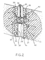
- Fig. 2 schematically depicts a tube-a-machette system for injection of grout into a formation, which may be employed in the method of present invention.
- a grout pipe 30 is installed in borehole 37.
- Lean cement grout 41 fills the space between grout pipe 30 and the wall of borehole 37.
- Grout pipe 30 has a plurality of ports 32 closed by tight-fitting rubber sleeves 33, acting as a check valve.
- Sleeve 33 is shown in closed position 34 and open position 35.
- Injection tube 31 moves double-ended packer 39 which isolates individual ports 32, permitting injection through isolated ports at specific depths.
- a grouting composition used in the present invention is injected through pipe 31 as shown by arrows.
- the grout is pumped under pressure which moves sleeve 33 away from port 32.
- the grout under pressure breaks through lean cement grout 41 into passage 42. In this way the grout is injected into the formation as shown by arrows, and forms a spreading grout region 40.
- An alternative procedure is to drill the borehole while inserting a 3 inch steel casing during drilling.
- the drill is removed and the steel casing remains in the borehole.
- the interior of the casing is filled with a lean cement grout (high water content).
- the above-described tube-a-machette is inserted into the casing while the lean grout is fluid, and then the casing is removed.
- the lean grout is allowed to harden, whereupon it seals the annular space around the tube-a-machette.
- the lean cement grout fractures when subjected to the impact of high pressure grout being injected through the ports of the tube-a-machette.
- the method of the present application is of particular use in cementing wellbores and in grouting porous gas - and petroleum - bearing formations, i.e. formations in which hydrocarbons such as natural gas and petroleum are found.
- These geological formations containing hydrocarbon deposits include porous reservoir rocks, sand, shale, sandstone, and limestone.
- the method of the invention has advantages in well drilling and production operations, and especially for primary or remedial cementing of a wellbore, such as squeeze cementing.
- Primary cementing involves introduction of cement into the space between the outside of the steel casing of the well and the borehole wall (or the inside of a previously set casing if a new casing was introduced). Cement slurry is pumped down the entire length of the casing, out the borehole joint and into said space.
- Remedial cementing concerns procedures to remedy undesired conditions in a well such as to shut off water flows or repair casing damages.
- the most common remedial cementing procedure is called squeeze cementing.
- Squeeze cementing has been described in the above publication as being the process of applying hydraulic pressure to a cement slurry to (1) force or "squeeze" the slurry into the desired location and (2) force water from the slurry after placement to create a mass which will remain in place and harden to provide a seal.
- the publication lists some reasons why squeeze cementing is done, as follows:
- MICROFINE cements used in the present method are cementitious grouting materials composed of ultrafine particles of slag and portland that exhibit excellent penetrability, strength and durability suitable for squeeze cementing of oil well matrices, especially for gas and water control.
- ultrafine cements in squeeze cementing is enhanced by ultrafine particle size for penetration of medium sands and finely cracked rock in oil well matrices.
- Filtration properties are excellent because of ultrafine particle size and addition of one percent dispersant lowers viscosity and extends initial hardening time at high temperatures in the oil well matrix.
- the present method therefore is suitable for the following squeeze cementing applications:
- the following properties of the ultrafine cement allow penetration of the oil well matrix.
- ultrafine cements in squeeze cementing is enhanced by ultrafine particle size for penetration of medium sands and finely cracked rock in oil well matrices. Filtration properties (ability to hold water are excellent because of ultrafine particle size and addition of dispersant lowers viscosity and extends initial hardening time at high temperatures in the oil well matrix.
- the MICROFINE slag/cement has excellent set time, initial hardening time and viscosity in well cementing. Longer set and hardening times at high temperature result from larger quantities of blast furnace slag in the M5 ultrafine cement. The longer initial hardening time allows for down hole cementing for deep wells. Appropriate accelerators and retarders may be used for varying well depths and temperatures.
- Fine sands and finely cracked rock around non-commercial well zones may be sealed with M5.
- a prudent practice in abandoning a set of perforations is to set a drillable squeeze packer and attempts to squeeze the abandoned perforations with a low fluid loss cement at less than fracturing pressure.
- Block squeeze is used before perforating for production to prevent fluid migration from either above or below. M5 will penetrate blocked matrix better than ordinary portland to more efficiently prevent fluid migration.
- Water is an integral part of all porous rock and is present in most oil and gas bearing formations. Migration of water may be controlled when larger quantities of low viscosity M5 slurry penetrate the matrix pore spaces at less than fracturing pressure.
- a common procedure is to squeeze off all the perforations in the oil and gas zones which may be done with M5 and then perforate at selected intervals.
- M5 may be used to seal off thief zones in the upper section of a slotted gravel pack liner. Using a combination of M5 and microflour, a thief zone may be sealed to increase production.
- the ultrafine cements have been found to be significant additions to cementitious materials for oil well cementing because of the following inherent properties:
- Ultrafine particle size, long initial hardening time and high hardened strength of the ultrafine cements may be enhanced by the use of modern polymer technology accelerators, retarders, dispersants and fluid loss polymers. Physical properties of the ultrafine cement may also be improved by the addition of silica fume, bentonite, sodium silicate and silica flour.
- M5 cement is available in the desired particle size. In some applications it will be advantageous to further grind all or part of the cement/slag, especially in the field, i.e. in locations near the formation to be grouted.
- the portland cement component may be further ground prior to mixing with slag by grinding particulate portland cement having a particle size wherein less than 10 wt. percent of the particles are larger than 10 micrometers in diameter to a particle size wherein less than 2 wt. percent of the particles are larger than 10 micrometers in diameter, in a tower mill at or near the location of said formation to be grouted.
- particulate slag and particulate portland cement may be co-ground to a particulate size wherein less than 2 wt. percent of the particles are larger than 10 micrometers in diameter in a tower mill at or near the location of said formation to be grouted.
- Mixtures of 75% MICROFINE slag and 25% MICROFINE portland are especially useful in oil well cementing and can be produced by such tower mill grinding.
- Apparatus and techniques for Tower mill grinding are known. Typically dry and wet Tower Mills are approximately 10 feet high and 2 feet diameter, charged with 1/2" stainless steel or ceramic balls, all internally rubber lined with a screw rotating at 35-85 rmp.
- Example 1 gives data on the properties of grout injected by the method of the invention.
- Neat grout is the grout in absence of sand, such as when injected into a rock formation.
- a gray color indicates that the cement is not fully hard
- a blue color shows that it is fully hard
- numerical values for compressive strength are expressed in kg/cm 2 .
- Experiment 60 was performed to determine set time, initial hardening time, compressive strength, clear and hard settlement for M5 MICROFINE cement and Type III Portland at 20, 40, 60 and 90°C.
- Type III Portland (Whitehall, LaFarge)
- Experiment 61 was performed to determine viscosity, clear settlement, set time, initial hardening time and compressive strength for M3 portland and M1 slag at 20, 40, 60 and 90°C.
- Compressive strength of 1:1 WC M5 is 4500 psi at 20°C compared with 2300 psi for other light weight blends at 27°C. This indicates that M5 MICROFINE cement has inherent properties for oil-well cementing when the combination of light weight slurry and high compressive strength is required.
- the properties determined were viscosity, set time, initial hardening time and strength of M5 at 1:1, 0.9:1, 0.8:1, 0.7:1 and 0.5:1 water cement ratios at 20, 60, 70 and 80°C.
Landscapes
- Chemical & Material Sciences (AREA)
- Engineering & Computer Science (AREA)
- Life Sciences & Earth Sciences (AREA)
- General Life Sciences & Earth Sciences (AREA)
- Inorganic Chemistry (AREA)
- Materials Engineering (AREA)
- Organic Chemistry (AREA)
- Ceramic Engineering (AREA)
- Mining & Mineral Resources (AREA)
- Geology (AREA)
- Structural Engineering (AREA)
- Physics & Mathematics (AREA)
- Chemical Kinetics & Catalysis (AREA)
- Fluid Mechanics (AREA)
- Environmental & Geological Engineering (AREA)
- Soil Sciences (AREA)
- Geochemistry & Mineralogy (AREA)
- General Engineering & Computer Science (AREA)
- High Energy & Nuclear Physics (AREA)
- Soil Conditioners And Soil-Stabilizing Materials (AREA)
- Consolidation Of Soil By Introduction Of Solidifying Substances Into Soil (AREA)
- Curing Cements, Concrete, And Artificial Stone (AREA)
Claims (10)
- Procédé pour sceller au ciment des formations poreuses porteuses de gaz- et de pétrole-, qui comprend l'injection dans ladite formation ou dans un trou de forage d'une composition comprenant :(a) de l'eau;(b) un laitier particulaire ayant une surface spécifique supérieure à environ 9 500 cm2/g avec moins de 3 pourcent en poids des particules dudit laitier ayant un diamètre supérieur à 7,8 micromètres; les proportions de l'eau et du laitier étant à l'intérieur d'un intervalle de rapport massique eau à laitier compris entre 0,3 : 1 et 10 : 1;(c) au moins un dispersant dans une quantité efficace pour disperser les particules dudit laitier particulaire; et(d) un aecélérateur dans une quantité efficace pour accélérer l'hydratation dudit laitier;
caractérisé par (1) la présence d'un matériau de ciment supplémentaire, la proportion du laitier étant d'au moins 75 pourcent en poids de la totalité du matériau de ciment et (2) la modification de la proportion de laitier dans la totalité du matériau de ciment pour régler la durée de prise et la durée de résistance au durcissement à la température de la formation à sceller au ciment, la proportion de laitier est par là augmentée pour obtenir des durées de prise et de résistance au durcissement plus longues et est abaissée pour obtenir des durées de prise et de résistance au durcissement plus courtes. - Procédé selon la revendication 1, dans lequel l'accélérateur comprend un oxyde, un hydroxyde ou un sel alcalin ou alcalino-terreux.
- Procédé selon la revendication 1 ou 2, qui comprend l'injection de ladite composition pour une cimentation première ou réparatrice dudit trou de forage.
- Procédé selon la revendication 1, 2 ou 3, dans lequel le laitier particulaire présente de plus mélangé avec lui du ciment de portland particulaire ayant une taille de particules dans laquelle moins de 2 pourcent en poids des particules dudit ciment de portland ont un diamètre supérieur à 10 micromètres et le ciment de portland active l'hydratation du laitier et remplace partiellement ou totalement ledit accélérateur (d).
- Procédé selon l'une quelconque des revendications précédentes qui comprend l'addition d'un ou plusieurs des composés suivants :(a) jusqu'à 2 pourcent d'un condensat de sulfonate de naphtalène-formaldéhyde, rapportés au poids total du laitier et du ciment de portland pour abaisser la viscosité et retarder la durée de prise;(b) de la farine de silice ajoutée dans une proportion dans laquelle la farine de silice est au plus de 50% du poids total de farine de silice, de laitier particulaire et de ciment de portland; et/ou(c) un retardateur ajouté dans une quantité efficace pour obtenir des durées de prise et de résistance au durcissement plus longues pour sceller au ciment dans des conditions de températures plus élevées de la formation.
- Procédé selon l'une quelconque des revendications 1 à 4, dans lequel la proportion de laitier est augmentée pour obtenir des durées de prise et de durcissement souhaitées plus longues pour sceller au ciment dans des conditions de températures plus élevées de la formation.
- Procédé selon l'une quelconque des revendications précédentes, dans lequel ledit laitier est un laitier particulaire qui est un laitier microfin ayant une surface spécifique supérieure à environ 10 000 cm2/g, de préférence supérieure à environ 13 000 cm2/g, avec moins de 3 pourcent en poids des particules dudit laitier ayant un diamètre supérieur à 7,8 micromètres; les proportions de l'eau et du laitier étant à l'intérieur d'un rapport massique eau à laitier compris entre 0,5 : 1 et 2 : 1.
- Procédé selon l'une quelconque des revendications précédentes, dans lequel le constituant de laitier présente de plus mélangé avec lui un ciment ayant une surface spécifique supérieure à environ 10 000 cm2/g avec moins d'environ 7 pourcent en poids de particules du ciment ayant un diamètre supérieur à 7,8 micromètres.
- Procédé selon l'une quelconque des revendications précédentes, dans lequel ledit matériau de ciment supplémentaire est du ciment de portland particulaire ayant une surface spécifique supérieure à environ 10 000 cm2/g avec moins de 2 pourcent en poids des particules dudit ciment ayant un diamètre supérieur à 12 micromètres.
- Procédé selon la revendication 9, dans lequel ledit ciment présente une surface spécifique supérieure à environ 12 000 cm2/g avec moins de 2 pourcent en poids des particules dudit ciment ayant un diamètre supérieur à 6 micromètres.
Applications Claiming Priority (2)
| Application Number | Priority Date | Filing Date | Title |
|---|---|---|---|
| US720239 | 1991-06-24 | ||
| US07/720,239 US5106423A (en) | 1988-12-02 | 1991-06-24 | Formation grouting method and composition useful therefor |
Publications (3)
| Publication Number | Publication Date |
|---|---|
| EP0521376A2 EP0521376A2 (fr) | 1993-01-07 |
| EP0521376A3 EP0521376A3 (en) | 1993-01-13 |
| EP0521376B1 true EP0521376B1 (fr) | 2000-04-12 |
Family
ID=24893222
Family Applications (1)
| Application Number | Title | Priority Date | Filing Date |
|---|---|---|---|
| EP19920110580 Expired - Lifetime EP0521376B1 (fr) | 1991-06-24 | 1992-06-23 | Méthode pour la cimentation de formations poreuses contenant du gaz et du pétrole |
Country Status (6)
| Country | Link |
|---|---|
| US (1) | US5106423A (fr) |
| EP (1) | EP0521376B1 (fr) |
| AU (1) | AU667469B2 (fr) |
| CA (1) | CA2072064C (fr) |
| DE (1) | DE69230899T2 (fr) |
| DK (1) | DK0521376T3 (fr) |
Cited By (2)
| Publication number | Priority date | Publication date | Assignee | Title |
|---|---|---|---|---|
| RU2471846C1 (ru) * | 2011-07-20 | 2013-01-10 | Общество с ограниченной ответственностью "ТюменНИИгипрогаз" | Тампонажный раствор |
| US9834719B2 (en) | 2010-11-30 | 2017-12-05 | Schlumberger Technology Corporation | Methods for servicing subterranean wells |
Families Citing this family (102)
| Publication number | Priority date | Publication date | Assignee | Title |
|---|---|---|---|---|
| US5275654A (en) * | 1989-02-24 | 1994-01-04 | Shell Oil Corporation | Cement sealing |
| US5673753A (en) * | 1989-12-27 | 1997-10-07 | Shell Oil Company | Solidification of water based muds |
| US5423379A (en) * | 1989-12-27 | 1995-06-13 | Shell Oil Company | Solidification of water based muds |
| US5830548A (en) | 1992-08-11 | 1998-11-03 | E. Khashoggi Industries, Llc | Articles of manufacture and methods for manufacturing laminate structures including inorganically filled sheets |
| US5720913A (en) | 1992-08-11 | 1998-02-24 | E. Khashoggi Industries | Methods for manufacturing sheets from hydraulically settable compositions |
| US5453310A (en) | 1992-08-11 | 1995-09-26 | E. Khashoggi Industries | Cementitious materials for use in packaging containers and their methods of manufacture |
| US5641584A (en) | 1992-08-11 | 1997-06-24 | E. Khashoggi Industries | Highly insulative cementitious matrices and methods for their manufacture |
| US5851634A (en) | 1992-08-11 | 1998-12-22 | E. Khashoggi Industries | Hinges for highly inorganically filled composite materials |
| US5631097A (en) | 1992-08-11 | 1997-05-20 | E. Khashoggi Industries | Laminate insulation barriers having a cementitious structural matrix and methods for their manufacture |
| US5582670A (en) | 1992-08-11 | 1996-12-10 | E. Khashoggi Industries | Methods for the manufacture of sheets having a highly inorganically filled organic polymer matrix |
| CA2137347A1 (fr) | 1992-08-11 | 1994-03-03 | Per Just Andersen | Contenants a prise hydraulique |
| US5314031A (en) * | 1992-10-22 | 1994-05-24 | Shell Oil Company | Directional drilling plug |
| US5309997A (en) * | 1992-10-22 | 1994-05-10 | Shell Oil Company | Well fluid for in-situ borehole repair |
| US5322124A (en) * | 1992-10-22 | 1994-06-21 | Shell Oil Company | Squeeze cementing |
| US5343950A (en) * | 1992-10-22 | 1994-09-06 | Shell Oil Company | Drilling and cementing extended reach boreholes |
| US5309999A (en) * | 1992-10-22 | 1994-05-10 | Shell Oil Company | Cement slurry composition and method to cement wellbore casings in salt formations |
| US5325922A (en) * | 1992-10-22 | 1994-07-05 | Shell Oil Company | Restoring lost circulation |
| US5301754A (en) * | 1992-10-22 | 1994-04-12 | Shell Oil Company | Wellbore cementing with ionomer-blast furnace slag system |
| US5275511A (en) * | 1992-10-22 | 1994-01-04 | Shell Oil Company | Method for installation of piles in offshore locations |
| US5269632A (en) * | 1992-10-22 | 1993-12-14 | Shell Oil Company | Method for strengthening the structural base of offshore structures |
| US5277519A (en) * | 1992-10-22 | 1994-01-11 | Shell Oil Company | Well drilling cuttings disposal |
| US5307877A (en) * | 1992-10-22 | 1994-05-03 | Shell Oil Company | Wellbore sealing with two-component ionomeric system |
| US5311944A (en) * | 1992-10-22 | 1994-05-17 | Shell Oil Company | Blast furnace slag blend in cement |
| US5285679A (en) * | 1992-10-22 | 1994-02-15 | Shell Oil Company | Quantification of blast furnace slag in a slurry |
| US5301752A (en) * | 1992-10-22 | 1994-04-12 | Shell Oil Company | Drilling and cementing with phosphate-blast furnace slag |
| US5314022A (en) * | 1992-10-22 | 1994-05-24 | Shell Oil Company | Dilution of drilling fluid in forming cement slurries |
| US5343951A (en) * | 1992-10-22 | 1994-09-06 | Shell Oil Company | Drilling and cementing slim hole wells |
| US5284513A (en) * | 1992-10-22 | 1994-02-08 | Shell Oil Co | Cement slurry and cement compositions |
| US5332040A (en) * | 1992-10-22 | 1994-07-26 | Shell Oil Company | Process to cement a casing in a wellbore |
| US5311945A (en) * | 1992-10-22 | 1994-05-17 | Shell Oil Company | Drilling and cementing with phosphate |
| MY112090A (en) * | 1992-10-22 | 2001-04-30 | Shell Int Research | Method for drilling and cementing a well |
| US5307876A (en) * | 1992-10-22 | 1994-05-03 | Shell Oil Company | Method to cement a wellbore in the presence of carbon dioxide |
| US5379843A (en) * | 1992-10-22 | 1995-01-10 | Shell Oil Company | Side-tracking cement plug |
| US5330006A (en) * | 1992-10-22 | 1994-07-19 | Shell Oil Company | Oil mud displacement with blast furnace slag/surfactant |
| US5343947A (en) * | 1992-10-22 | 1994-09-06 | Shell Oil Company | Anchor plug for open hole test tools |
| US5343952A (en) * | 1992-10-22 | 1994-09-06 | Shell Oil Company | Cement plug for well abandonment |
| US5351759A (en) * | 1992-10-22 | 1994-10-04 | Shell Oil Company | Slag-cement displacement by direct fluid contact |
| US5332041A (en) * | 1992-12-30 | 1994-07-26 | Halliburton Company | Set-activated cementitious compositions and methods |
| US5333690A (en) * | 1992-12-31 | 1994-08-02 | Shell Oil Company | Cementing with blast furnace slag using spacer |
| US5346012A (en) * | 1993-02-01 | 1994-09-13 | Halliburton Company | Fine particle size cement compositions and methods |
| US5543186A (en) | 1993-02-17 | 1996-08-06 | E. Khashoggi Industries | Sealable liquid-tight, thin-walled containers made from hydraulically settable materials |
| US5305831A (en) * | 1993-02-25 | 1994-04-26 | Shell Oil Company | Blast furnace slag transition fluid |
| US5322389A (en) * | 1993-03-04 | 1994-06-21 | Conversion Systems, Inc. | Method for transporting a cementitious mixture to an underground space |
| US5383521A (en) * | 1993-04-01 | 1995-01-24 | Halliburton Company | Fly ash cementing compositions and methods |
| US5389146A (en) * | 1993-04-12 | 1995-02-14 | Baroid Technology, Inc. | Grouting composition and method |
| US5361842A (en) * | 1993-05-27 | 1994-11-08 | Shell Oil Company | Drilling and cementing with blast furnace slag/silicate fluid |
| US5361841A (en) * | 1993-05-27 | 1994-11-08 | Shell Oil Company | Drilling and cementing with blast furnace slag/polyalcohol fluid |
| US5358044A (en) * | 1993-05-27 | 1994-10-25 | Shell Oil Company | Drilling and cementing with blast furnace slag/soluble/insoluble alcohol |
| US5738921A (en) | 1993-08-10 | 1998-04-14 | E. Khashoggi Industries, Llc | Compositions and methods for manufacturing sealable, liquid-tight containers comprising an inorganically filled matrix |
| US5370181A (en) * | 1993-08-13 | 1994-12-06 | Shell Oil Company | Anti gas-migration cementing |
| US5379840A (en) * | 1993-08-19 | 1995-01-10 | Shell Oil Company | High temperature well cementing with low grade blast furnace slag |
| US5407879A (en) * | 1993-09-29 | 1995-04-18 | American Colloid Company | Method of improving the contaminant resistance of a smectite clay by rewetting and impregnating the clay with a water-soluble polymer, and redrying the polymer-impregnated clay |
| US5447197A (en) * | 1994-01-25 | 1995-09-05 | Bj Services Company | Storable liquid cementitious slurries for cementing oil and gas wells |
| US5421409A (en) * | 1994-03-30 | 1995-06-06 | Bj Services Company | Slag-based well cementing compositions and methods |
| DE4447961B4 (de) * | 1994-08-12 | 2004-08-05 | Dyckerhoff Ag | Verwendung eines Trockengemenges zur Herstellung einer Bindemittelsuspension |
| DE4428692C2 (de) | 1994-08-12 | 1996-09-05 | Dyckerhoff Ag | Trockengemenge zur Herstellung einer Zementsuspension sowie Verfahren zu seiner Herstellung und Vorrichtung zur Durchführung des Verfahrens |
| US5547024A (en) * | 1994-12-06 | 1996-08-20 | Bj Services Co | Method of using construction grade cement in oil and gas wells |
| US5709267A (en) * | 1995-10-23 | 1998-01-20 | Amoco Corporation | Aqueous particulate dispersion for reducing the water influx rate into a wellbore |
| US5588489A (en) * | 1995-10-31 | 1996-12-31 | Halliburton Company | Lightweight well cement compositions and methods |
| AU3486197A (en) * | 1996-06-27 | 1998-01-14 | Bj Services Company, U.S.A. | Lightweight thermally stable cement compositions and method of use |
| US5814147A (en) * | 1997-01-21 | 1998-09-29 | Envirotrench Company | Method for strengthening and improving clay soils |
| ATE387412T1 (de) * | 1997-05-15 | 2008-03-15 | Constr Res & Tech Gmbh | Zementzusammensetzung mit hohem anteil an durch puzzolan ersetzten zement und verträglichmachende gemische dafür |
| US6076997A (en) * | 1997-12-03 | 2000-06-20 | Mbt Holding Ag | Deep mix soil stabilization method |
| US6145591A (en) * | 1997-12-12 | 2000-11-14 | Bj Services Company | Method and compositions for use in cementing |
| US6230804B1 (en) | 1997-12-19 | 2001-05-15 | Bj Services Company | Stress resistant cement compositions and methods for using same |
| US6173778B1 (en) | 1998-05-27 | 2001-01-16 | Bj Services Company | Storable liquid systems for use in cementing oil and gas wells |
| DK1044175T3 (da) | 1998-08-14 | 2003-03-17 | Mbt Holding Ag | Cementblandinger med højt pozzolanindhold |
| CA2339118C (fr) | 1998-08-14 | 2010-10-19 | Mbt Holding Ag | Melange coule sec pour ciment |
| US6561269B1 (en) * | 1999-04-30 | 2003-05-13 | The Regents Of The University Of California | Canister, sealing method and composition for sealing a borehole |
| US6861459B2 (en) * | 1999-07-09 | 2005-03-01 | Construction Research & Technology Gmbh | Oligomeric dispersant |
| BR9902726B1 (pt) * | 1999-07-13 | 2010-07-13 | composições estocáveis para cimentação de poços de óleo e gás. | |
| CA2316059A1 (fr) | 1999-08-24 | 2001-02-24 | Virgilio C. Go Boncan | Methodes et compositions pouvant etre utilisees pour la cimentation en milieux froids |
| US6258160B1 (en) * | 1999-09-07 | 2001-07-10 | Halliburton Energy Services, Inc. | Methods and compositions for grouting heat exchange pipe |
| CA2318703A1 (fr) | 1999-09-16 | 2001-03-16 | Bj Services Company | Compositions et methodes de cimentation utilisant des particules elastiques |
| FR2801049B1 (fr) * | 1999-11-16 | 2002-01-04 | Ciments D Obourg Sa | Composition de beton a ultra-hautes performances a base de laitier |
| JP4474102B2 (ja) * | 2001-02-08 | 2010-06-02 | 博 穀田 | 無機溶解促進剤,非晶質高濃度水溶性無機化合物,無溶剤無機発泡体、不燃有機無機発泡体及び加熱急硬化性組成物 |
| CA2370875A1 (fr) | 2001-02-15 | 2002-08-15 | B.J. Services Company | Composes cimentaires souples haute temperature et methodes pour les utiliser |
| US6663596B2 (en) | 2001-08-13 | 2003-12-16 | Scimed Life Systems, Inc. | Delivering material to a patient |
| US6749682B2 (en) | 2002-04-29 | 2004-06-15 | Ut-Battelle, Llc | Controlling the set of carbon-fiber embedded cement with electric current |
| RU2254303C1 (ru) * | 2004-06-28 | 2005-06-20 | Вердиян Мэлс Аспандарович | Способ управления процессом получения цементной сухой строительной смеси |
| RU2334713C2 (ru) * | 2006-05-18 | 2008-09-27 | Вердиян Мэлс Аспандарович | Способ управления процессом приготовления бетонной смеси |
| US7810566B2 (en) * | 2006-06-30 | 2010-10-12 | Halliburton Energy Services Inc. | Settable compositions free of portland cement and associated methods of use |
| RU2312415C1 (ru) * | 2006-11-30 | 2007-12-10 | Зао "Экоатом" | Способ иммобилизации жидких радиоактивных отходов, содержащих воду и нефтепродукты |
| US20100270016A1 (en) * | 2009-04-27 | 2010-10-28 | Clara Carelli | Compositions and Methods for Servicing Subterranean Wells |
| CN101705808B (zh) * | 2009-12-11 | 2012-05-30 | 安东石油技术(集团)有限公司 | 套管外存在窜槽的油气井的控流过滤器管柱分段控流方法 |
| KR101129219B1 (ko) * | 2010-02-23 | 2012-03-26 | 주식회사 포스코건설 | 액상 초고점성 및 유동성 그라우트재를 이용한 강관 속채움 방법 |
| KR101066587B1 (ko) | 2010-02-23 | 2011-09-21 | 주식회사 리엔 | 액상 초고점성 및 유동성 그라우트재를 이용한 속채움 구조체 시공 방법 |
| FI20105172A7 (fi) * | 2010-02-23 | 2011-08-24 | Uretek Worldwide Oy | Menetelmä ja laitteisto materiaalin injektoimiseksi maaperään |
| US9950952B2 (en) | 2010-11-30 | 2018-04-24 | Schlumberger Technology Corporation | Methods for servicing subterranean wells |
| FI20106346A7 (fi) | 2010-12-20 | 2012-06-21 | Uretek Worldwide Oy | Menetelmä ja sovitelma rakenteen tukemiseksi |
| US8162058B1 (en) | 2011-10-27 | 2012-04-24 | Halliburton Energy Services Inc. | Slag compositions and methods of use |
| FR2994977B1 (fr) * | 2012-09-03 | 2016-01-22 | Poweltec | Utilisation de polymères thermo épaississants dans l'industrie d'exploitation gazière et pétrolière |
| JP6220195B2 (ja) * | 2013-09-02 | 2017-10-25 | 国立大学法人 東京大学 | 高性能無機系ひび割れ注入材を用いた漏水ひび割れ止水材料及びその止水工法 |
| CN104314515A (zh) * | 2014-10-23 | 2015-01-28 | 神华集团有限责任公司 | 一种煤矿钻孔的封孔方法及封孔装置 |
| US10377674B2 (en) * | 2015-02-02 | 2019-08-13 | Carolyn Dry | Concrete coatings and compositions that absorb carbon dioxide |
| CA2913306A1 (fr) * | 2015-11-26 | 2017-05-26 | Eko Tech4Trans Pvt Ltd. | Ciment active chimiquement au moyen de dechets industriels |
| US10589238B2 (en) | 2016-03-14 | 2020-03-17 | Schlumberger Technology Corporation | Mixing system for cement and fluids |
| US10703958B2 (en) | 2016-03-31 | 2020-07-07 | Halliburton Energy Services, Inc. | Co-grinding slag with other material for hydraulic binders |
| CN112608042A (zh) * | 2020-12-19 | 2021-04-06 | 湖北工业大学 | 一种由水淬铜渣湿磨法制备超细铜尾砂填充胶凝材料的方法 |
| CN114086950B (zh) * | 2021-10-21 | 2023-03-10 | 航天凯天环保科技股份有限公司 | 一种地质勘探取样方法 |
| CN114737915B (zh) * | 2022-04-19 | 2024-02-09 | 安徽理工大学 | 一种深部开采突水冲击地压防治装置 |
| CN115159913A (zh) * | 2022-07-29 | 2022-10-11 | 物华能源科技有限公司 | 一种射孔弹静态侵彻用高强度柱状混凝土配方及目标靶 |
Family Cites Families (9)
| Publication number | Priority date | Publication date | Assignee | Title |
|---|---|---|---|---|
| US2646360A (en) * | 1949-08-29 | 1953-07-21 | Phillips Petroleum Co | Low-water-loss cement slurry |
| GR68405B (fr) * | 1979-05-31 | 1981-12-29 | Flowcon Oy | |
| US4443260A (en) * | 1982-06-14 | 1984-04-17 | Chiyoda Chemical Engineering & Constr., Co., Ltd. | Method for strengthening soft soil |
| US4761183A (en) * | 1987-01-20 | 1988-08-02 | Geochemical Corporation | Grouting composition comprising slag |
| NO165673C (no) * | 1987-11-16 | 1991-03-20 | Elkem As | Hydraulisk sementoppslemming. |
| US4897119A (en) * | 1988-01-11 | 1990-01-30 | Geochemical Corporation | Aqueous dispersion of ground slag |
| US4911584A (en) * | 1988-08-09 | 1990-03-27 | Luis Arenzana | Method for soil injection |
| US5026215A (en) * | 1988-12-02 | 1991-06-25 | Geochemical Corporation | Method of grouting formations and composition useful therefor |
| US5086850A (en) * | 1991-01-08 | 1992-02-11 | Halliburton Company | Well bore drilling direction changing method |
-
1991
- 1991-06-24 US US07/720,239 patent/US5106423A/en not_active Expired - Lifetime
-
1992
- 1992-06-22 AU AU18456/92A patent/AU667469B2/en not_active Ceased
- 1992-06-23 EP EP19920110580 patent/EP0521376B1/fr not_active Expired - Lifetime
- 1992-06-23 DK DK92110580T patent/DK0521376T3/da active
- 1992-06-23 DE DE69230899T patent/DE69230899T2/de not_active Expired - Fee Related
- 1992-06-23 CA CA002072064A patent/CA2072064C/fr not_active Expired - Lifetime
Non-Patent Citations (1)
| Title |
|---|
| WILLIAM J. CLARKE ET AL.: "Alkali Activated Slag and Portland / Slag UF Cements", MATERIALS RESEARCH SOCIETY SYMPOSIUM PROCEEDINGS, vol. 179, 1989, PITTSBURGH, PENSYLVANIA, pages 219 - 232 * |
Cited By (2)
| Publication number | Priority date | Publication date | Assignee | Title |
|---|---|---|---|---|
| US9834719B2 (en) | 2010-11-30 | 2017-12-05 | Schlumberger Technology Corporation | Methods for servicing subterranean wells |
| RU2471846C1 (ru) * | 2011-07-20 | 2013-01-10 | Общество с ограниченной ответственностью "ТюменНИИгипрогаз" | Тампонажный раствор |
Also Published As
| Publication number | Publication date |
|---|---|
| AU667469B2 (en) | 1996-03-28 |
| DK0521376T3 (da) | 2000-09-11 |
| EP0521376A3 (en) | 1993-01-13 |
| DE69230899T2 (de) | 2000-12-14 |
| EP0521376A2 (fr) | 1993-01-07 |
| CA2072064C (fr) | 2003-10-14 |
| AU1845692A (en) | 1993-01-07 |
| US5106423A (en) | 1992-04-21 |
| DE69230899D1 (de) | 2000-05-18 |
| CA2072064A1 (fr) | 1992-12-25 |
Similar Documents
| Publication | Publication Date | Title |
|---|---|---|
| EP0521376B1 (fr) | Méthode pour la cimentation de formations poreuses contenant du gaz et du pétrole | |
| US5026215A (en) | Method of grouting formations and composition useful therefor | |
| EP0605114B1 (fr) | Cimentation de puits | |
| US8276666B2 (en) | Sealant compositions and methods of use | |
| US7527688B2 (en) | Cementitious compositions for oil well cementing applications | |
| US9676989B2 (en) | Sealant compositions comprising cement kiln dust and tire-rubber particles and method of use | |
| US5346012A (en) | Fine particle size cement compositions and methods | |
| US5123487A (en) | Repairing leaks in casings | |
| US5127473A (en) | Repair of microannuli and cement sheath | |
| CA2058869C (fr) | Cimentation primaire | |
| US7156173B2 (en) | Cement compositions useful in oil and gas wells | |
| US20140073537A1 (en) | Sealant Compositions and Methods of Use | |
| AU2008285481B2 (en) | Sealant compositions and methods of use | |
| US7740066B2 (en) | Additives for high alumina cements and associated methods | |
| US7604053B2 (en) | Methods of cementing with lightweight cement composition | |
| EP0572261A1 (fr) | Compositions de ciment ultrafines à prise retardée | |
| EP0659702A1 (fr) | Procédé de cimentation d'une zone souterraine | |
| EP0564294A1 (fr) | Cimentation par compression | |
| CA2186868A1 (fr) | Compositions de cimentation des puits a base de scories et procedes de production | |
| WO2009071962A2 (fr) | Compositions de ciment pour des applications de cimentation de puits de pétrole | |
| US11485895B2 (en) | Cement with resilient latex polymer | |
| AU2013204279B2 (en) | Sealant compositions and methods of use |
Legal Events
| Date | Code | Title | Description |
|---|---|---|---|
| PUAI | Public reference made under article 153(3) epc to a published international application that has entered the european phase |
Free format text: ORIGINAL CODE: 0009012 |
|
| PUAL | Search report despatched |
Free format text: ORIGINAL CODE: 0009013 |
|
| AK | Designated contracting states |
Kind code of ref document: A2 Designated state(s): BE DE DK FR GB NL |
|
| AK | Designated contracting states |
Kind code of ref document: A3 Designated state(s): BE DE DK FR GB NL |
|
| 17P | Request for examination filed |
Effective date: 19930707 |
|
| 17Q | First examination report despatched |
Effective date: 19950222 |
|
| GRAG | Despatch of communication of intention to grant |
Free format text: ORIGINAL CODE: EPIDOS AGRA |
|
| GRAG | Despatch of communication of intention to grant |
Free format text: ORIGINAL CODE: EPIDOS AGRA |
|
| GRAH | Despatch of communication of intention to grant a patent |
Free format text: ORIGINAL CODE: EPIDOS IGRA |
|
| GRAH | Despatch of communication of intention to grant a patent |
Free format text: ORIGINAL CODE: EPIDOS IGRA |
|
| RAP1 | Party data changed (applicant data changed or rights of an application transferred) |
Owner name: SCHLUMBERGER TECHNOLOGY CORPORATION |
|
| GRAA | (expected) grant |
Free format text: ORIGINAL CODE: 0009210 |
|
| AK | Designated contracting states |
Kind code of ref document: B1 Designated state(s): BE DE DK FR GB NL |
|
| REF | Corresponds to: |
Ref document number: 69230899 Country of ref document: DE Date of ref document: 20000518 |
|
| ET | Fr: translation filed | ||
| REG | Reference to a national code |
Ref country code: DK Ref legal event code: T3 |
|
| PLBE | No opposition filed within time limit |
Free format text: ORIGINAL CODE: 0009261 |
|
| STAA | Information on the status of an ep patent application or granted ep patent |
Free format text: STATUS: NO OPPOSITION FILED WITHIN TIME LIMIT |
|
| 26N | No opposition filed | ||
| REG | Reference to a national code |
Ref country code: GB Ref legal event code: IF02 |
|
| PGFP | Annual fee paid to national office [announced via postgrant information from national office to epo] |
Ref country code: FR Payment date: 20020610 Year of fee payment: 11 |
|
| PGFP | Annual fee paid to national office [announced via postgrant information from national office to epo] |
Ref country code: DK Payment date: 20020614 Year of fee payment: 11 |
|
| PGFP | Annual fee paid to national office [announced via postgrant information from national office to epo] |
Ref country code: DE Payment date: 20020626 Year of fee payment: 11 |
|
| PGFP | Annual fee paid to national office [announced via postgrant information from national office to epo] |
Ref country code: NL Payment date: 20020628 Year of fee payment: 11 |
|
| PGFP | Annual fee paid to national office [announced via postgrant information from national office to epo] |
Ref country code: BE Payment date: 20020827 Year of fee payment: 11 |
|
| PG25 | Lapsed in a contracting state [announced via postgrant information from national office to epo] |
Ref country code: DK Free format text: LAPSE BECAUSE OF NON-PAYMENT OF DUE FEES Effective date: 20030630 Ref country code: BE Free format text: LAPSE BECAUSE OF NON-PAYMENT OF DUE FEES Effective date: 20030630 |
|
| BERE | Be: lapsed |
Owner name: *SCHLUMBERGER TECHNOLOGY CORP. Effective date: 20030630 |
|
| PG25 | Lapsed in a contracting state [announced via postgrant information from national office to epo] |
Ref country code: NL Free format text: LAPSE BECAUSE OF NON-PAYMENT OF DUE FEES Effective date: 20040101 Ref country code: DE Free format text: LAPSE BECAUSE OF NON-PAYMENT OF DUE FEES Effective date: 20040101 |
|
| REG | Reference to a national code |
Ref country code: DK Ref legal event code: EBP |
|
| PG25 | Lapsed in a contracting state [announced via postgrant information from national office to epo] |
Ref country code: FR Free format text: LAPSE BECAUSE OF NON-PAYMENT OF DUE FEES Effective date: 20040227 |
|
| NLV4 | Nl: lapsed or anulled due to non-payment of the annual fee |
Effective date: 20040101 |
|
| REG | Reference to a national code |
Ref country code: FR Ref legal event code: ST |
|
| PGFP | Annual fee paid to national office [announced via postgrant information from national office to epo] |
Ref country code: GB Payment date: 20110622 Year of fee payment: 20 |
|
| REG | Reference to a national code |
Ref country code: GB Ref legal event code: PE20 Expiry date: 20120622 |
|
| PG25 | Lapsed in a contracting state [announced via postgrant information from national office to epo] |
Ref country code: GB Free format text: LAPSE BECAUSE OF EXPIRATION OF PROTECTION Effective date: 20120622 |