EP0521461A2 - Dispositif de manoeuvre pour le soutirage de liquide sous pression d'un fût - Google Patents
Dispositif de manoeuvre pour le soutirage de liquide sous pression d'un fût Download PDFInfo
- Publication number
- EP0521461A2 EP0521461A2 EP92111058A EP92111058A EP0521461A2 EP 0521461 A2 EP0521461 A2 EP 0521461A2 EP 92111058 A EP92111058 A EP 92111058A EP 92111058 A EP92111058 A EP 92111058A EP 0521461 A2 EP0521461 A2 EP 0521461A2
- Authority
- EP
- European Patent Office
- Prior art keywords
- lever
- handle
- locking pin
- slide
- housing
- Prior art date
- Legal status (The legal status is an assumption and is not a legal conclusion. Google has not performed a legal analysis and makes no representation as to the accuracy of the status listed.)
- Granted
Links
- 239000007788 liquid Substances 0.000 title claims abstract description 12
- 238000010079 rubber tapping Methods 0.000 title description 2
- 235000013405 beer Nutrition 0.000 claims abstract 2
- 230000006835 compression Effects 0.000 claims description 23
- 238000007906 compression Methods 0.000 claims description 23
- 230000000694 effects Effects 0.000 claims description 6
- CURLTUGMZLYLDI-UHFFFAOYSA-N Carbon dioxide Chemical compound O=C=O CURLTUGMZLYLDI-UHFFFAOYSA-N 0.000 claims description 4
- 229910002092 carbon dioxide Inorganic materials 0.000 claims description 2
- 239000001569 carbon dioxide Substances 0.000 claims description 2
- 238000006073 displacement reaction Methods 0.000 claims description 2
- 230000008719 thickening Effects 0.000 claims 1
- 239000000463 material Substances 0.000 description 3
- 230000001174 ascending effect Effects 0.000 description 1
- 238000011161 development Methods 0.000 description 1
- 230000018109 developmental process Effects 0.000 description 1
- 238000003780 insertion Methods 0.000 description 1
- 230000037431 insertion Effects 0.000 description 1
- 238000007789 sealing Methods 0.000 description 1
Images

Classifications
-
- B—PERFORMING OPERATIONS; TRANSPORTING
- B67—OPENING, CLOSING OR CLEANING BOTTLES, JARS OR SIMILAR CONTAINERS; LIQUID HANDLING
- B67D—DISPENSING, DELIVERING OR TRANSFERRING LIQUIDS, NOT OTHERWISE PROVIDED FOR
- B67D1/00—Apparatus or devices for dispensing beverages on draught
- B67D1/08—Details
- B67D1/0829—Keg connection means
- B67D1/0839—Automatically operating handles for locking or unlocking a connector to or from a keg
-
- B—PERFORMING OPERATIONS; TRANSPORTING
- B67—OPENING, CLOSING OR CLEANING BOTTLES, JARS OR SIMILAR CONTAINERS; LIQUID HANDLING
- B67D—DISPENSING, DELIVERING OR TRANSFERRING LIQUIDS, NOT OTHERWISE PROVIDED FOR
- B67D1/00—Apparatus or devices for dispensing beverages on draught
- B67D1/08—Details
- B67D1/0829—Keg connection means
- B67D1/0841—Details
- B67D1/0848—Locking means
Definitions
- the invention relates to an actuating device according to the preamble of claim 1.
- the lever In order to release the locking of the swivel lever or handle for the purpose of adjustment from one extreme position to the other, the lever is pressed against the force of the compression spring against the swivel lever or handle, the lever performing a rotary movement about its pivot point. Since the outer areas of the pivot lever or handle and lever are arranged relatively far from each other, there is the possibility of pinching fingers or hand parts.
- a tap head is also known in which the slide is actuated in the direction of its one extreme position "valve open” by the fact that a swivel lever connected to the slide and gripping it with its fork-shaped end grips one end with a handle around its The pivot point is pivoted downward until a locking pin under the action of a compression spring which is axially displaceably mounted in the pivoting lever engages in a recess formed on the tap head housing, in which position the slide then presses the flow paths for an inflowing pressure medium against the pressure of a relatively strong valve spring leaking liquid releases.
- valve closed takes place simply by pulling the locking pin out of the recess of the housing, whereupon the force of the relatively strong valve spring constantly acting on the slide follows the slide with simultaneous automatic pivoting of the pivot lever moves upwards until the valve spring has correspondingly relaxed the slide in its upper end position and at the same time the swivel lever has reached its upper extreme position.
- the swivel lever with handle is kinematically designed so that the pin-shaped part of the swivel lever adjoining the fork-shaped part and containing the locking pin with compression spring in a through hole is rotatably mounted near the fork-shaped swivel lever part by means of pins and recesses in the side grip shells and in the area the rear end of the locking pin a U-shaped lever is provided, which is rotatably mounted with its two side legs by means of pins and recesses at a distance from the pivot lever axis in the side handle scales to be expanded towards its rear end and with its web provided with an elongated hole arranged the locking pin and is held by a locking element arranged at the end.
- the angular position of the U-shaped lever with respect to the axis of the locking pin or the pivoting lever corresponding to it, as well as the length ratios are chosen so that the locking pin against the unactuated, ie released handle Force of the compression spring is retracted so far into the pin-shaped part of the pivoting lever that its tip protrudes into the fork-shaped part of the pivoting lever by an amount corresponding to the depth of the corresponding housing recess, so that the locking pin is under spring pressure.
- a major disadvantage of this device which is good per se, is that even a relatively slight action on the outer end of the handle, because of the relatively large lever arm with respect to the pivot point of the handle, can cause the handle to pivot and thereby the locking pin out of it Locked position is withdrawn and thus the unwanted unlocking of the pivot lever and, as a result, an unintentional closing of the valve is effected.
- the present invention sets itself the task of creating a device which is equally effective in its effect, but which is simpler in structure and more secure against unwanted external influences. This object is achieved with a device according to the characterizing part of claim 1.
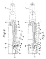
- the dispensing head of FIG. 1 has in its housing 1 the slide 2, which is arranged as a tubular element and is displaceable in the axial direction.
- the edge 3 which has a U-profile-shaped cross-section and extends over a substantial part of the housing circumference, the housing 1 is pushed and fastened in a known manner onto the edge, not shown, of a connection formed on the barrel or keg or a so-called tap plant.
- the seals 4 are arranged in the upper part of the housing and the seal 5 is arranged in the lower part of the housing, these seals providing temporary sealing between the housing 1 and the slide 2 in a known manner, depending on the slide position.
- connection 6 is formed on the side, which is used for the connection to a compressed gas source, not shown, for example a carbon dioxide bottle.
- a tuning fork with a fork-shaped part 8 'encompassing the slider 2 on both sides and a pin-shaped part 8' connected to this adjoining pivot lever 8 is pivotably mounted by means of the bolt 30.
- the fork-shaped part 8 'of the pivot lever 8 includes the slider 2 in its constricted area 2'.
- the thickened end 10 'of the locking pin 10 is engaged in the position of the pivot lever 8 shown in Figure 1 in the groove 18 of the neck 19 on the housing 1.
- the projection 19 is provided with the curved sliding surface 20, the curvature of which corresponds to the radius to the pivot point in the eye 7.
- the shoulder 19 is provided with the bevel 21.
- locking pin 10 prevents the pivot lever 8 from being adjusted against the pressure of the valve spring, not shown, from its position shown, that is to say, when the handle 12 is released, it ensures that the open position of the angle lever 15 is maintained Valve.
- the locking pin 10 is held by the compression spring 11 with a sufficient force in the groove 18, so that there is no danger that the pivot lever 8 is inadvertently pivoted out of its position.
- the force of the compression spring 11 is of course chosen or dimensioned so that that is, the ratios and dimensions of the individual parts are chosen and matched to one another such that the locking pin 10 is pressed into the groove 18 with such a force that even in the event of unintended action on the outer end of the pivoting lever 8 or the handle 12 Locking is maintained.
- this also applies, taking into account a possibly more or less strong beveled or conical design of the tip of the locking pin 10 engaging in the groove 18.
- the dispensing valve (not shown) is closed, the handle 12 is gripped by hand and the free end of the angle lever 15 is pressed against the handle 12.
- the leg of the angle lever 15 located on the end of the locking pin 10 is pivoted or tilted to a corresponding extent, and the locking pin 10 is thereby pulled out of the groove 18 with the tip of the compression spring 11 being compressed, as can clearly be seen in FIG. 3.
- the pivot lever 8 can now be pivoted upwards around the eye 7 or the bolt 30 attached to it.
- pivot lever 8 is pivoted only so far that the front surface of the tip of the locking pin 10 comes into the region of the curved surface 20, after which the relatively strong valve spring, not shown, is able to To move the slide 2 while pivoting the pivot lever 8 further into its upper extreme position, as indicated in FIG. 1 by means of dash-dotted lines in the right half.
- pivot lever 8 takes place in that the shoulder 22 of the slider 2 on the fork-shaped part 8 'of the pivot lever 8 comes to rest and accordingly, when the slider 2 is moved upward, the pivot lever 8 is pivoted about its pivot point, the tip of the locking pin 10 first over the surface 20 and then with the handle 12 and angle lever 15 released, slides over the bevel 21, whereby the pivot lever 8 is then, as it were, locked in its upper extreme position by the tip of the locking pin 10 under pressure from the compression spring 11.
- the upper extreme position of the pivot lever 8 is essentially determined by the upward movement of the slide 2, which in turn takes place as a function of the closing operation of the valve, not shown, under the action of the valve spring, also not shown, and is ended when the valve is completely closed, with the slide 2 simultaneously by means of its annular surface 25 in cooperation with the lower of the two seals 4, the access of pressure medium through the connecting piece 6 and the bores 24 is prevented.
- the two legs of the angle lever 15 are of course arranged at such an angle to one another that it is ensured that by pressing the free leg sufficiently far against the handle 12, the other leg arranged on the locking pin 10 and provided with the elongated hole 28 has such an inclined position relative to the axis of the pivot lever 8, through which the locking pin 10 is withdrawn against the force of the compression spring 11 so far that the tip of the locking pin 10 is completely pulled out of the groove 18 with certainty and accordingly there are no obstacles to the pivoting of the pivot lever 8.
- the outer shape and the dimensions of the handle 12 can be adapted in many ways to the respective wishes and needs, ie the handle 12 can be designed, for example, with a circular, but also be formed with a rectangular or other cross-section and with a more or less non-slip surface and / or surface shape.
- the handle 12 is secured against rotation on the pivot lever 8, for example — as shown in the figures — by means of the projection 26 of the pin-shaped part 8 ′ of the pivot lever 8 engaging in groove 27 of the handle 12.
- the lid 17 of the handle 12 can be screwed into the handle 12 in the form of a screw cap or simply inserted into the end of the handle as a plug-in cap, for example with a slight press fit .
- a bayonet-type fastening of the cover in the handle could also be provided.
- the cover is expediently provided with surfaces or the like which enable the cover to be easily and conveniently detached and attached.
- the tuning fork-shaped pivot lever 8 again has a fork-shaped part 8 'on the housing side and a pin-shaped part 8' adjoining this.
- This pin-shaped part 8 ⁇ is here also provided with a through-bore 9 having a ring-shaped constriction 8′′′.
- the locking pin 10 is arranged with its two ends protruding. Between the thickened end 10 'and the annular collar constriction 8 ′′′ the compression spring 11 is arranged.
- the thickened end 10 'protruding from the bore 9' of the locking pin 10 could of course again be frustoconical or as shown in FIGS. 1 to 3, or in another way, so that it can be used in a correspondingly safe manner in the intended, not shown, Engages groove of the housing attachment, also not shown.
- the handle 12 On the pin-shaped part 8 ⁇ of the pivot lever 8, the handle 12 is arranged and with the interposition of one leg of the actuating angle lever 15 by means of the locking nut 16 attached to the threaded end 13 of the locking pin 10 and secured via the compression spring 11 with its front end face held against the web 32 of the pivot lever 8. As indicated by the nose 33 overlapping the web 32, the handle 12 arranged with a more or less large clearance on the pin-side part 8 Part of the pivoting lever 8 can be additionally locked, whereby of course also several, possibly different and differently shaped or designed and locking elements arranged at other points can be provided.
- the handle 12 is provided on its underside with the groove-shaped recess 34.
- the opening 31 on the handle 12 is formed such that a sufficiently wide gap is present between the rear end of the handle 12 and the leg of the lever 15 protruding into the opening 31, which gap is present when the Lever 15, ie Pushing the free leg 29 against the handle 12, an angular pivoting or inclination of the other leg of the lever 15 allows.
- a cover cap or a closure cover 17 is again provided here.
- the locking nut 16 By adjusting the locking nut 16 on the threaded part 13 of the locking pin 10, the latter can also be shifted to a certain extent in the longitudinal direction and at the same time the effect of the compression spring 11 can be changed accordingly, the locking pin 10 then engages more or less deeply in the groove of the housing attachment, not shown.
Landscapes
- Preventing Unauthorised Actuation Of Valves (AREA)
- Investigating Or Analyzing Materials By The Use Of Ultrasonic Waves (AREA)
- Degasification And Air Bubble Elimination (AREA)
- Mechanically-Actuated Valves (AREA)
- Devices For Dispensing Beverages (AREA)
Applications Claiming Priority (2)
| Application Number | Priority Date | Filing Date | Title |
|---|---|---|---|
| DE4121817 | 1991-07-02 | ||
| DE4121817A DE4121817A1 (de) | 1991-07-02 | 1991-07-02 | Zapfkopf fuer die entnahme von fluessigkeiten unter druck aus einem behaelter |
Publications (3)
| Publication Number | Publication Date |
|---|---|
| EP0521461A2 true EP0521461A2 (fr) | 1993-01-07 |
| EP0521461A3 EP0521461A3 (en) | 1993-03-17 |
| EP0521461B1 EP0521461B1 (fr) | 1994-12-28 |
Family
ID=6435219
Family Applications (1)
| Application Number | Title | Priority Date | Filing Date |
|---|---|---|---|
| EP92111058A Expired - Lifetime EP0521461B1 (fr) | 1991-07-02 | 1992-06-30 | Dispositif de manoeuvre pour le soutirage de liquide sous pression d'un fût |
Country Status (3)
| Country | Link |
|---|---|
| EP (1) | EP0521461B1 (fr) |
| AT (1) | ATE116267T1 (fr) |
| DE (2) | DE4121817A1 (fr) |
Cited By (8)
| Publication number | Priority date | Publication date | Assignee | Title |
|---|---|---|---|---|
| EP0972745A1 (fr) * | 1998-07-11 | 2000-01-19 | HIWI SCHANKANLAGEN GmbH i.K . | Verrouillage pour une tête de distribution |
| KR100644394B1 (ko) | 2006-02-01 | 2006-11-13 | 김유식 | 맥주용 디스펜서 헤드 구조 |
| KR100680995B1 (ko) | 2006-01-03 | 2007-02-12 | 최형선 | 생맥주 공급 장치 |
| US7491197B2 (en) | 2003-03-06 | 2009-02-17 | Csl Behring Gmbh | Fluid transfer device |
| CN103523730A (zh) * | 2013-10-25 | 2014-01-22 | 玉环县和成铜业有限公司 | 一种啤酒桶的出酒阀 |
| DE102014101652A1 (de) | 2014-02-11 | 2015-08-13 | Cmb Schankanlagen Gmbh | Zapfkopf für ein Getränkefass |
| DE102015119330A1 (de) | 2015-11-10 | 2017-05-11 | Cmb Schankanlagen Gmbh | Zapfkopf für ein Getränkefass |
| ES2932202A1 (es) * | 2021-06-30 | 2023-01-16 | Mahou S A | Grifo dispensador de bebidas |
Families Citing this family (1)
| Publication number | Priority date | Publication date | Assignee | Title |
|---|---|---|---|---|
| DE102004027449A1 (de) * | 2004-06-04 | 2005-12-29 | Stiebel Eltron Gmbh & Co. Kg | Zapfvorrichtung mit Höhenverstellung |
Family Cites Families (8)
| Publication number | Priority date | Publication date | Assignee | Title |
|---|---|---|---|---|
| DE6813295U (de) * | 1968-12-12 | 1969-04-24 | Weigel Handelsgmbh Fa | Einhand-betaetigungsvorrichtung fuer insbesondere abzapfvorrichtungen |
| DE2627891C2 (de) * | 1976-06-22 | 1987-05-07 | Grittmann, Günter, 7519 Eppingen | Vorrichtung zum Ausschenken von Flüssigkeiten |
| NL192448C (nl) * | 1986-01-21 | 1997-08-04 | Vsh Fabrieken Bv | Tapkop, koppelbaar op een tapstangsamenstel van een vat. |
| NL192449C (nl) * | 1986-01-21 | 1997-08-04 | Vsh Fabrieken Bv | Tapkop voor aanbrenging op een tapstangsamenstel van een vat onder gebruikmaking van een afdichtingsring. |
| DE3709334A1 (de) * | 1987-03-21 | 1988-10-06 | Romneya Trading Co Ltd | Keg-zapfer |
| DK157536C (da) * | 1987-06-03 | 1990-07-02 | Micro Matic As | Tappehoved til tapning af vaesker under tryk fra en beholder |
| DE8809942U1 (de) * | 1988-08-04 | 1988-12-01 | Eutec Josef Breitwisch & Co. GmbH, 5000 Köln | Zapfkopf für Getränkebehälter, insbesondere Bierfässer |
| DE9200225U1 (de) * | 1992-01-10 | 1992-04-09 | Josef Breitwisch & Co, 5000 Köln | Zapfkopf für Getränkebehälter, insbesondere Bierfässer |
-
1991
- 1991-07-02 DE DE4121817A patent/DE4121817A1/de active Granted
-
1992
- 1992-06-30 DE DE59201071T patent/DE59201071D1/de not_active Expired - Fee Related
- 1992-06-30 AT AT92111058T patent/ATE116267T1/de not_active IP Right Cessation
- 1992-06-30 EP EP92111058A patent/EP0521461B1/fr not_active Expired - Lifetime
Cited By (11)
| Publication number | Priority date | Publication date | Assignee | Title |
|---|---|---|---|---|
| EP0972745A1 (fr) * | 1998-07-11 | 2000-01-19 | HIWI SCHANKANLAGEN GmbH i.K . | Verrouillage pour une tête de distribution |
| US7491197B2 (en) | 2003-03-06 | 2009-02-17 | Csl Behring Gmbh | Fluid transfer device |
| KR100680995B1 (ko) | 2006-01-03 | 2007-02-12 | 최형선 | 생맥주 공급 장치 |
| KR100644394B1 (ko) | 2006-02-01 | 2006-11-13 | 김유식 | 맥주용 디스펜서 헤드 구조 |
| CN103523730A (zh) * | 2013-10-25 | 2014-01-22 | 玉环县和成铜业有限公司 | 一种啤酒桶的出酒阀 |
| CN103523730B (zh) * | 2013-10-25 | 2016-03-23 | 玉环县和成铜业有限公司 | 一种啤酒桶的出酒阀 |
| DE102014101652A1 (de) | 2014-02-11 | 2015-08-13 | Cmb Schankanlagen Gmbh | Zapfkopf für ein Getränkefass |
| US9718662B2 (en) | 2014-02-11 | 2017-08-01 | CMB Schankalagen GmbH | Dispenser head for a beverage cask |
| DE102015119330A1 (de) | 2015-11-10 | 2017-05-11 | Cmb Schankanlagen Gmbh | Zapfkopf für ein Getränkefass |
| DE102015119330B4 (de) | 2015-11-10 | 2020-06-18 | Cmb Schankanlagen Gmbh | Zapfkopf für ein Getränkefass |
| ES2932202A1 (es) * | 2021-06-30 | 2023-01-16 | Mahou S A | Grifo dispensador de bebidas |
Also Published As
| Publication number | Publication date |
|---|---|
| DE4121817C2 (fr) | 1993-06-17 |
| EP0521461A3 (en) | 1993-03-17 |
| ATE116267T1 (de) | 1995-01-15 |
| EP0521461B1 (fr) | 1994-12-28 |
| DE59201071D1 (de) | 1995-02-09 |
| DE4121817A1 (de) | 1993-01-07 |
Similar Documents
| Publication | Publication Date | Title |
|---|---|---|
| DE60133073T2 (de) | Abgabeeinheit für die gleichzeitige Abgabe von zwei Produkten | |
| EP0901003B1 (fr) | Dispensateur de bouteilles | |
| EP1708936B1 (fr) | Adaptateur pour bombes aerosols | |
| DE69117513T2 (de) | Auftragsvorrichtung für mehr oder weniger dickflüssige produkte | |
| EP0738668B1 (fr) | Actionneur pour aérosol muni d'une poignée | |
| EP0455650B1 (fr) | Tete de cannette pour robinetterie de tonnelets | |
| DE4341229A1 (de) | Pipettensystem | |
| DE2447426A1 (de) | Spruehvorrichtung | |
| EP2285703A1 (fr) | Bouchon tire-pousse pour un contenant à boisson | |
| EP2172141B1 (fr) | Vaisselle de cuisson dotée d'un élément de poignée ou de tige amovible | |
| EP0662069B1 (fr) | Dispositif de mise en perce pour cannelle d'un tonnelet | |
| EP0521461B1 (fr) | Dispositif de manoeuvre pour le soutirage de liquide sous pression d'un fût | |
| EP3552989B1 (fr) | Adaptateur pour le distributeur de produit et distributeur de produit | |
| AT405823B (de) | Förderbüchse für eine rohrpostanlage | |
| DE68901827T2 (de) | Mit einer sicherheitsvorrichtung versehene einrichtung zum abgeben einer bestimmten dosierung von einer sich in einem verformbaren behaelter befindlichen fluessigkeit. | |
| DE68908721T2 (de) | Kindsicherer verschluss für eine flasche oder ähnliche behälter. | |
| DE3300198A1 (de) | Verschluss fuer behaelter insbesondere tuben | |
| DE102006036517A1 (de) | Abgabekopf für einen ein fließfähiges Medium unter Druck aufnehmenden Druckbehälter | |
| DE3701433C2 (fr) | ||
| DE19831186C2 (de) | Betätigungsvorrichtung für den Arretierstift des Schwenkhebels einer Einrichtung für die Entnahme von Flüssigkeiten unter Druck aus einem Behälter | |
| DE3844428A1 (de) | Aufbruchsichere verankerung fuer zapfrohre an bierbehaeltern | |
| LU87400A1 (de) | Ventilanordnung zum fuellen und entleeren eines gasbehaelters | |
| DE2452495A1 (de) | Spruehkopf fuer einen aerosolbehaelter | |
| DE19649112A1 (de) | Vorrichtung zum Öffnen und/oder Verschließen von Kronenkorkenflaschen | |
| EP4711304A1 (fr) | Capuchon de distribution pour récipients sous pression et récipient doté d'un récipient sous pression et capuchon de distribution |
Legal Events
| Date | Code | Title | Description |
|---|---|---|---|
| PUAI | Public reference made under article 153(3) epc to a published international application that has entered the european phase |
Free format text: ORIGINAL CODE: 0009012 |
|
| AK | Designated contracting states |
Kind code of ref document: A2 Designated state(s): AT BE CH DE DK ES FR GB GR IT LI LU NL SE |
|
| PUAL | Search report despatched |
Free format text: ORIGINAL CODE: 0009013 |
|
| AK | Designated contracting states |
Kind code of ref document: A3 Designated state(s): AT BE CH DE DK ES FR GB GR IT LI LU NL SE |
|
| 17P | Request for examination filed |
Effective date: 19930226 |
|
| 17Q | First examination report despatched |
Effective date: 19940325 |
|
| GRAA | (expected) grant |
Free format text: ORIGINAL CODE: 0009210 |
|
| AK | Designated contracting states |
Kind code of ref document: B1 Designated state(s): AT BE CH DE DK ES FR GB GR IT LI LU NL SE |
|
| PG25 | Lapsed in a contracting state [announced via postgrant information from national office to epo] |
Ref country code: IT Free format text: LAPSE BECAUSE OF FAILURE TO SUBMIT A TRANSLATION OF THE DESCRIPTION OR TO PAY THE FEE WITHIN THE PRE;WARNING: LAPSES OF ITALIAN PATENTS WITH EFFECTIVE DATE BEFORE 2007 MAY HAVE OCCURRED AT ANY TIME BEFORE 2007. THE CORRECT EFFECTIVE DATE MAY BE DIFFERENT FROM THE ONE RECORDED.SCRIBED TIME-LIMIT Effective date: 19941228 Ref country code: GR Free format text: LAPSE BECAUSE OF FAILURE TO SUBMIT A TRANSLATION OF THE DESCRIPTION OR TO PAY THE FEE WITHIN THE PRESCRIBED TIME-LIMIT Effective date: 19941228 Ref country code: GB Effective date: 19941228 Ref country code: NL Effective date: 19941228 Ref country code: ES Free format text: THE PATENT HAS BEEN ANNULLED BY A DECISION OF A NATIONAL AUTHORITY Effective date: 19941228 Ref country code: FR Effective date: 19941228 Ref country code: BE Effective date: 19941228 Ref country code: DK Effective date: 19941228 |
|
| REF | Corresponds to: |
Ref document number: 116267 Country of ref document: AT Date of ref document: 19950115 Kind code of ref document: T |
|
| REF | Corresponds to: |
Ref document number: 59201071 Country of ref document: DE Date of ref document: 19950209 |
|
| PG25 | Lapsed in a contracting state [announced via postgrant information from national office to epo] |
Ref country code: SE Effective date: 19950328 |
|
| EN | Fr: translation not filed | ||
| NLV1 | Nl: lapsed or annulled due to failure to fulfill the requirements of art. 29p and 29m of the patents act | ||
| PG25 | Lapsed in a contracting state [announced via postgrant information from national office to epo] |
Ref country code: AT Effective date: 19950630 Ref country code: LU Free format text: LAPSE BECAUSE OF NON-PAYMENT OF DUE FEES Effective date: 19950630 Ref country code: LI Effective date: 19950630 Ref country code: CH Effective date: 19950630 |
|
| GBV | Gb: ep patent (uk) treated as always having been void in accordance with gb section 77(7)/1977 [no translation filed] |
Effective date: 19941228 |
|
| PLBI | Opposition filed |
Free format text: ORIGINAL CODE: 0009260 |
|
| 26 | Opposition filed |
Opponent name: D.S.I. JOSEF BREITWISCH & CO. GMBH Effective date: 19950927 |
|
| REG | Reference to a national code |
Ref country code: CH Ref legal event code: PL |
|
| PLBF | Reply of patent proprietor to notice(s) of opposition |
Free format text: ORIGINAL CODE: EPIDOS OBSO |
|
| PLBF | Reply of patent proprietor to notice(s) of opposition |
Free format text: ORIGINAL CODE: EPIDOS OBSO |
|
| PLAB | Opposition data, opponent's data or that of the opponent's representative modified |
Free format text: ORIGINAL CODE: 0009299OPPO |
|
| R26 | Opposition filed (corrected) |
Opponent name: D.S.I. GETRAENKEARMATUREN GMBH & CO. KG Effective date: 19950927 |
|
| PLBO | Opposition rejected |
Free format text: ORIGINAL CODE: EPIDOS REJO |
|
| APAC | Appeal dossier modified |
Free format text: ORIGINAL CODE: EPIDOS NOAPO |
|
| APAE | Appeal reference modified |
Free format text: ORIGINAL CODE: EPIDOS REFNO |
|
| APAC | Appeal dossier modified |
Free format text: ORIGINAL CODE: EPIDOS NOAPO |
|
| PLBQ | Unpublished change to opponent data |
Free format text: ORIGINAL CODE: EPIDOS OPPO |
|
| PLAB | Opposition data, opponent's data or that of the opponent's representative modified |
Free format text: ORIGINAL CODE: 0009299OPPO |
|
| R26 | Opposition filed (corrected) |
Opponent name: D.S.I. GETRAENKEARMATUREN GMBH & CO. KG Effective date: 19950927 |
|
| 29U | Proceedings interrupted after grant according to rule 142 epc |
Effective date: 19971222 |
|
| 29W | Proceedings resumed after grant [after interruption of proceedings according to rule 142 epc] |
Effective date: 19980626 |
|
| RAP2 | Party data changed (patent owner data changed or rights of a patent transferred) |
Owner name: D.S.I. GETRAENKEARMATUREN GMBH & CO. KG |
|
| RAP2 | Party data changed (patent owner data changed or rights of a patent transferred) |
Owner name: HIWI SCHANKANLAGEN GMBH I.K . |
|
| RAP2 | Party data changed (patent owner data changed or rights of a patent transferred) |
Owner name: D.S.I. GETRAENKEARMATUREN GMBH & CO. KG |
|
| APAC | Appeal dossier modified |
Free format text: ORIGINAL CODE: EPIDOS NOAPO |
|
| PLBN | Opposition rejected |
Free format text: ORIGINAL CODE: 0009273 |
|
| STAA | Information on the status of an ep patent application or granted ep patent |
Free format text: STATUS: OPPOSITION REJECTED |
|
| 27O | Opposition rejected |
Effective date: 19990714 |
|
| PGFP | Annual fee paid to national office [announced via postgrant information from national office to epo] |
Ref country code: DE Payment date: 20040823 Year of fee payment: 13 |
|
| APAH | Appeal reference modified |
Free format text: ORIGINAL CODE: EPIDOSCREFNO |
|
| PG25 | Lapsed in a contracting state [announced via postgrant information from national office to epo] |
Ref country code: DE Free format text: LAPSE BECAUSE OF NON-PAYMENT OF DUE FEES Effective date: 20060103 |
|
| PLAB | Opposition data, opponent's data or that of the opponent's representative modified |
Free format text: ORIGINAL CODE: 0009299OPPO |