EP0521714A2 - Kabelverbinder - Google Patents
Kabelverbinder Download PDFInfo
- Publication number
- EP0521714A2 EP0521714A2 EP92306102A EP92306102A EP0521714A2 EP 0521714 A2 EP0521714 A2 EP 0521714A2 EP 92306102 A EP92306102 A EP 92306102A EP 92306102 A EP92306102 A EP 92306102A EP 0521714 A2 EP0521714 A2 EP 0521714A2
- Authority
- EP
- European Patent Office
- Prior art keywords
- cable
- core
- cores
- separator
- branch
- Prior art date
- Legal status (The legal status is an assumption and is not a legal conclusion. Google has not performed a legal analysis and makes no representation as to the accuracy of the status listed.)
- Ceased
Links
Images

Classifications
-
- H—ELECTRICITY
- H01—ELECTRIC ELEMENTS
- H01R—ELECTRICALLY-CONDUCTIVE CONNECTIONS; STRUCTURAL ASSOCIATIONS OF A PLURALITY OF MUTUALLY-INSULATED ELECTRICAL CONNECTING ELEMENTS; COUPLING DEVICES; CURRENT COLLECTORS
- H01R9/00—Structural associations of a plurality of mutually-insulated electrical connecting elements, e.g. terminal strips or terminal blocks; Terminals or binding posts mounted upon a base or in a case; Bases therefor
- H01R9/03—Connectors arranged to contact a plurality of the conductors of a multiconductor cable, e.g. tapping connections
- H01R9/031—Connectors arranged to contact a plurality of the conductors of a multiconductor cable, e.g. tapping connections for multiphase cables, e.g. with contact members penetrating insulation of a plurality of conductors
Definitions
- This invention relates to a connector, and particularly, though not exclusively, to a branch-off connector, for an electric cable, especially a power cable.
- a connector and particularly, though not exclusively, to a branch-off connector, for an electric cable, especially a power cable.
- the invention finds application primarily with low voltage cables, that is to say cables operating at voltages at or less than about 1 kV, it is also applicable to higher voltage cables.
- a branch cable takes electricity from a main cable to supply equipment that is located on a spur.
- the main cable has its outer jacket and any other common outer components of the cable cut back so as to expose the individual, insulated cores of the cable, defining a branch-off region.
- a branch-off connector is mounted on the exposed cores in the branch-off region and has one set of contacts, which may be screw contacts, for connecting to respective ones of the core conductors of the main cable, and another set of contacts for receiving the core conductors of the branch cable. Electrical connection between the branch cable and the main cable is made. Subsequently, electrical insulation and environmental protection is applied to the branch-off region.
- One known method of insulating and protecting the branch-off region involves the positioning of a two-part rigid plastic box around the region, being sealed at each end on to the cable jacket. Epoxy resin is poured in to fill the box and to exclude air from around the connector and between the cores. The resin is allowed to cool and cure.
- This method has the disadvantages of using potentially toxic materials, and of having to mix two components together, and then pour them into the box before any appreciable curing takes place. Consequently, adequate ventilation has to be ensured, thus precluding use of the method in confined areas, care has to be taken with the viscous resin, and the jointer has to wait until the resin has cooled and fully cured before power can be re-supplied to the main cable.
- the curing period can be as long as ten to fifteen hours, and if power is applied too soon, gas bubbles may be evolved from the resin, giving rise to voids in the insulation and thus the risk of poor electrical performance of the branch joint. Furthermore, the potting that is involved with this method in practice precludes re-entry of the joint without its destruction.
- Another known method of insulating and protecting a branch-off region is to use a heat-recoverable polymeric insulating wraparound sleeve.
- a heat-recoverable polymeric insulating wraparound sleeve available from Raychem with its rail and channel closure system, is wrapped around the branch-off region and extends at each end over the cable jacket.
- the longitudinal sleeve edges, each having a rail formed therealong, are brought into abutment and the channel member slid over them to secure them together.
- Heat for example from a gas torch, is then applied to the sleeve to cause it to shrink into conformity with the underlying components.
- the sleeve is internally coated so as to provide a seal along its closure region and on to the cable. Power may be restored immediately to the main cable, and the shrinking technique is quick, relatively safe, and involves little skill.
- the joint may be re-entered by cutting away the sleeve, and the required action to the connector or cable carried out. Insulation and protection may be re-applied to the branch-off region using a fresh recoverable sleeve.
- European Patent Application Publication No. 0 253 670 discloses a connector that overcomes, or at least alleviates, the last-mentioned difficulties. However, the problem still remains of ensuring that the correct cores of the multi-core main and branch cables are interconnected.
- Multi-core electric power cables often are constructed such that the neutral core is of a different shape and/or size from the phase cores, and the present invention thus provides cable joints and components for cable joints that allow the joint to be formed if and only if the neutral cores are connected to one another. Should an incorrect matching have been made, the joint cannot be completed, thus maintaining a high level of safety and protection for operators.
- a core separator having a plurality of arms, suitable for providing separation between the cores of a multicore electrical cable, wherein two adjacent arms of the separator are arranged so as, in use, to lie between cores and to co-operate with each other so as to receive a specific one only of the cores therebetween.
- the separator can be fitted to the main cable only in one orientation.
- the said two adjacent arms are so shaped that the core-receiving sector formed thereby is shaped and/or sized so as to receive only the said specific core.
- the core separator may comprise three or four arms, for use with three- or four-core cables respectively.
- the core separator may be of generally cruciform shape for use with a four-core cable.
- the core separator may be formed from two or more interengaging parts, and when for example it comprises two parts, they may be arranged to interengage by an arm of one of the parts being arranged to pass, preferably as a push-fit, through the other part, preferably in only a single orientation.
- the sector formed by said two adjacent arms may be of generally circular cross-section and the sector formed by any other pair of adjacent arms may be of generally triangular cross-section.
- a cable connecting arrangement for making a connection between the multiple cores of a main cable and respective cores of a branch cable, the arrangement comprising at least one pair of contact members biassed to one of a closed and an open position and a cam system arranged to move the contacts against the biasing thereby respectively to open or to close the contacts on to respective ones of the cores of one of the cables.
- the contacts are insulation-piercing contacts.
- a cable joint may comprise a core separator and a cable connecting arrangement, each as herein described, and a particular one of the contact members of the arrangements may be shaped so as to enter only that sector of the core separator between the said two adjacent arms and thus so as to be engageable with only that cable core disposable therein.
- the core separator is arranged so as to be mountable on one of the cables, usually the main cable, only in a single orientation, and the contact arrangement is arranged such that one of the contacts is physically different from the others such that only that contact may engage the specific, usually the neutral, core of the cable.
- the cable joint may be arranged such that the connector cannot physically be closed around the main cable unless the core separator is positioned with the correct orientation around the cores for receiving the cable connection arrangement.
- a connector for an electric cable comprising a core separator and/or a cable connection arrangement, each as herein described.
- an electrical cable joint between a four-core main cable and a four-core branch cable is provided.
- the present invention also provides methods of forming cable joints whereby incorrect electrical connection to the neutral cores is prevented, or at least its occurrence minimised.
- the methods comprise the mounting of a core separator on a cable as
- the invention is particularly, though not exclusively, concerned with the provision of a branch-off connector and branch-off connecting method, thus dealing with a branch-off region of a cable (the main cable) that is partway along its length and at which outer components of the cable (such as outer jacket and insulation) have been removed to expose the individually insulated cores so that they may be correctly identified for subsequent connection.
- the invention is also applicable to an in-line joint, whereby a sealed connection can be provided at an end of a cable for subsequent connection to an end of another cable.
- a cable may have a region at its end at which the core or cores (usually individually insulated) are exposed, and the connector of the invention may be sealingly connected thereto.
- a branch-off region of a cable needs to be sealed against ingress of moisture, so that no electrically conductive path is thereby formed between a live conductor and earth, or, in the case of a multi-conductor cable only, between one live conductor (ie. phase) of the cable and another.
- moisture may penetrate a damaged outer cable jacket and travel along the cable along a core or between the cores.
- the core insulation is broken, eg. pierced, at a branch-off region, it is necessary to ensure that insulation is re-applied.
- the sealed housing and of connector of the present invention ensures this.
- the cable joint of the present invention may contain a thixotropic mastic, or a gel, or other suitable sealing means, contained within an outer housing for the core separator and/or the core connecting arrangement of the invention.
- a thixotropic mastic, or a gel, or other suitable sealing means contained within an outer housing for the core separator and/or the core connecting arrangement of the invention.
- the housing may be electrically insulating, but it may be a metal component that is held at earth potential, for example also being electrically connected to the neutral cores of the cables.
- a four core cable may have three phase cores each of generally triangular shape and a neutral core of circular cross-section.
- the core separator is then arranged so as to form a circular aperture in the sector adjacent two of its arms so that it can be inserted between the cores of the main cable, without them being cut, only in the orientation with the neutral core disposed in that sector.
- the cable connector can then be provided with an orientation plate that carries the contact members and that is arranged to receive the core separator only in one orientation. This can be done by providing the plate with slots of different widths to receive correspondingly-sized arms of the core separator.
- the contact members are each electrically connected to respective ones of the cores of the branch cable. That contact member which is connected to the neutral core of the branch cable is then arranged to be electrically connected to an insulation-piercing contact of a configuration, for example size, that can enter only the neutral sector of the core separator.
- a camming mechanism can be arranged to urge pairs of the contact members through the insulation and on to the conductors of respective ones of the cores of the main cable. This action can be effected from outside a housing that contains the branch-off region, the core separator and the cable connecting arrangement. By insulating the camming mechanism from the contact members, the electrical interconnection between the branch and main cables can be safely made even when the main cable is electrically live.
- branch cables could be mechanically connected to the main cable at one time, left without power supplied thereto (even though the main cable is live), and electrically connected to the main cable at a later time. All of this can be done using the connector and method of the present invention without disturbing the sealing of the branch-off region.
- sealing is required primarily to prevent ingress of water and water vapour into the housing. Such moisture may have entered the cable away from the branch-off region, through a breach in the cable jacket for example, and may pass along the inside thereof between the cores. It is essential then to ensure that at the branch-off region, where the core conductor insulation has been interrupted, no moisture can form a conductive path between any of the cores (whether at phase voltage or at earth potential).
- the sealing may also conveniently be required to replace the electrical insulation of the removed cable jacket, in the case of a multi-core cable.
- the sealing may conveniently be achieved by having a quantity of electrically insulating and water resistant cross-linked sealant material, such as gel for example, in one or both of two housing parts before they are secured together around the branch-off region to form the complete housing.
- the quantity of gel, or other sealant material is chosen such that all of the airspaces around the conductor cores and within the housing are filled when the housing is formed.
- the following materials when cross-linked are suitable for providing an electrically insulating and water resistant seal of the branch-off region: gels, greases, mastic, unvulcanised soft rubbers, or a water curable material such as silicone.
- the material is a gel, this is preferably a suitable material as described in Patent Application Publication No. WO 86/01634, the contents of which are herein incorporated by this reference.
- one part 2 of a two part insulating core separator 4 is of generally rectangular shape and has a narrow slot 6 extending therethrough, and a cut-out portion 8 in one arm thereof.
- the other part 10 is of general T-shape with a cut-out portion 12 in one arm thereof.
- the stem 13 of the T of part 10 is of a width so as to be a tight push fit into the slot 6 of the part 2.
- Figure 3 shows the parts 2 and 10 interengaged to form the elongate insulating core separator 4 of general cruciform section having four arms. As can be seen, two of the adjacent arms are relatively thick and extensions 14 and 16 thereof define a sector 18 of different configuration from that of the other three sectors.
- the sector 18 is of generally circular shape with access to it being defined by the width of the cut-outs 8 and 12.
- the sector 18 is thus shaped and sized to receive a circular-sectioned neutral core of a four core electric power cable, whereas the other sectors can receive the generally triangular-shaped cores of the three phase conductors of the cable.
- the outer components of a power cable such as the outer insulation and any screening layers, are removed in the region where the branch joint is to be made, thus exposing the individually insulated cores, say four, of the cable.
- the part 2 of the separator 4 is then inserted between two of the cores so as to separate them into pairs, and the part 10 is inserted between each one of those pairs and through the slot 6 of the part 2 to separate each of the cores from the other.
- the core separator can only be inserted between the cores in a single orientation such that the differently-configured neutral core is accommodated in the sector 18.
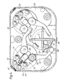
- Figure 4 shows the core separator 4 mounted in a cable connecting arrangement inside a metal housing 20 of the branch joint.
- the thickness of the extremities of the two arms defining the neutral sector 18 of the separator 4 is greater than that of the other two arms, and an orientation plate 22 mounted in the housing 20 has four slots, two of which are thicker than the others, around a circular aperture therein for receiving the separator 4.
- the two slots 24, 26 ensure that the sector 18 is located within the segment of arc between then. In this manner, it is ensured that the neutral core of the cable is located in this specified segment of the cable connecting arrangement.
- the orientation plate 22 also carries a pair of contact arrangements 28, 30, the arrangement 28 being shown in its open configuration and arrangement 30 closed.
- the contact arrangement 28 has a pair of cranked contact members 32, 34 hinged partway therealong about pins 36, 38.
- Actuating members 40, 42 are pivotally attached to the outer ends of the contact members 32, 34, and are operated as a cam mechanism by a common actuator 44.
- the actuator 44 is operated from outside the housing 20, access being obtained through an aperture 45.
- the inner ends of the contact members 32, 34 carry insulation-piercing contacts 46, 48.
- the contact arrangement 30 is constructed in the same way as the arrangement 28.
- the contact 46 of the contact member 32 which is associated with the neutral sector of the core separator 4, is of less thickness (in the direction perpendicular to the plane of Figure 4), than the other three contacts 48, and alone is able to pass through the gap formed by the cut-outs 8, 12 ( Figure 3).
- the contact member 32 is uniquely associated with the neutral core of the main cable.
- the actuating members 40, 42 Upon operation of the actuators 44 to urge them from the position shown in contact arrangement 28 to that of arrangement 30, the actuating members 40, 42 cause the contact members 32, 34 to pivot about their axes 36, 38, and thus the contacts 46 and 48 are urged into their respective sectors of the core separator4.
- the contacts 46,48 pierce the insulation of the cable cores and establish direct contact with the four respective core conductors (not shown).
- connection from the core conductors of the main cable via the connection arrangements 28, 30 is effected by connections from the four pivot pins 36, 38 to respective ones of the four cores of the branch cable (not shown), with the contact member 32 and its pin 36 being clearly marked as the neutral core connection.
- the actuators 44 and actuating members 40, 42 are made of electrically insulating material, so that standard non-insulated tools (spanner, screwdriver etc) can be introduced through the housing apertures 45 for effecting the connections to the cores of the main cable.
- the orientation plate 22 and the housing 20 can conveniently be electrically connected together, and to earth potential, and to the neutral cores of the main and branch cables. Should the cables themselves not be blocked against flow of water therealong, the housing 20 can be filled with suitable water blocking material such as gel or a thixotropic mastic.
- the housing 20 can itself be completely sealed around the main and branch cables to ensure a watertight joint.
- the main cable can be centre-stripped to receive the core separator, the connection arrangement and housing can be fitted therearound, and sealed, and the thus secured main cable can safely be left until a branch cable needs to be added at a later time.
- the branch cable can be inserted and connected to the pins 36, 38 (by means not shown) without disturbing the sealing around the branch region.
- operation of the contact arrangements 32, 34 by means of the actuators 44 can be effected subsequently from outside the sealed housing 20 through the apertures 45, which can then be plugged.
- the branch cable can be connected at the time of making the fitment around the main cable, but its energisation can be carried out subsequently (via the apertures 45). It will be appreciated that connection of the branch cable to the main cable can be carried out without the need to cut the main cable, and also without the need to de-energise the main cable.
Landscapes
- Cable Accessories (AREA)
Applications Claiming Priority (2)
| Application Number | Priority Date | Filing Date | Title |
|---|---|---|---|
| GB919114439A GB9114439D0 (en) | 1991-07-03 | 1991-07-03 | Cable connector |
| GB9114439 | 1991-07-03 |
Publications (2)
| Publication Number | Publication Date |
|---|---|
| EP0521714A2 true EP0521714A2 (de) | 1993-01-07 |
| EP0521714A3 EP0521714A3 (en) | 1993-08-25 |
Family
ID=10697802
Family Applications (1)
| Application Number | Title | Priority Date | Filing Date |
|---|---|---|---|
| EP19920306102 Ceased EP0521714A3 (en) | 1991-07-03 | 1992-07-01 | Cable connector |
Country Status (2)
| Country | Link |
|---|---|
| EP (1) | EP0521714A3 (de) |
| GB (1) | GB9114439D0 (de) |
Cited By (1)
| Publication number | Priority date | Publication date | Assignee | Title |
|---|---|---|---|---|
| WO2017214682A1 (en) * | 2016-06-17 | 2017-12-21 | Guzu Holdings Pty Ltd | An electrical connector |
Family Cites Families (5)
| Publication number | Priority date | Publication date | Assignee | Title |
|---|---|---|---|---|
| DE2408005C3 (de) * | 1974-02-20 | 1981-08-13 | Felten & Guilleaume Schaltanlagen Gmbh, 4150 Krefeld | Kabelmuffe, insbesondere für Starkstromkabel im Niederspannungsbereich |
| DE2444440C3 (de) * | 1974-09-17 | 1980-04-30 | Arcus Elektrotechnik Alois Schiffmann Gmbh, 8000 Muenchen | Mehrphasige elektrische Klemmvorrichtung |
| FR2524210A1 (fr) * | 1982-03-23 | 1983-09-30 | Electricite De France | Pince de raccordement pour prise de terre |
| GB8617560D0 (en) * | 1986-07-18 | 1986-08-28 | Raychem Gmbh | Cable connector |
| FR2645683B1 (fr) * | 1989-04-10 | 1996-06-14 | Mars Actel | Boite de raccordement pour branchement de cables de derivation sur un cable principal |
-
1991
- 1991-07-03 GB GB919114439A patent/GB9114439D0/en active Pending
-
1992
- 1992-07-01 EP EP19920306102 patent/EP0521714A3/en not_active Ceased
Cited By (1)
| Publication number | Priority date | Publication date | Assignee | Title |
|---|---|---|---|---|
| WO2017214682A1 (en) * | 2016-06-17 | 2017-12-21 | Guzu Holdings Pty Ltd | An electrical connector |
Also Published As
| Publication number | Publication date |
|---|---|
| EP0521714A3 (en) | 1993-08-25 |
| GB9114439D0 (en) | 1991-08-21 |
Similar Documents
| Publication | Publication Date | Title |
|---|---|---|
| EP0582777B1 (de) | Motoranschlussblock, insbesondere für Elektromotoren | |
| DE3273698D1 (en) | Cable jointing connector and method | |
| US3819848A (en) | Wiring harnesses | |
| CA2371741C (en) | Low voltage re-enterable splice enclosure | |
| US4692564A (en) | Cable support system | |
| US6086406A (en) | Branching connector for an underground cable | |
| WO1998053531A1 (en) | Cable splice closure | |
| CA2175173A1 (en) | Cable splice enclosure | |
| JPS5939970B2 (ja) | 内部伝熱ジヤケツトを持つたスプライス・コネクタ | |
| SE8402942D0 (sv) | Dispositif de jonction pour liaison aero-souterraine de cables electriques a basse tension | |
| EP0253670B1 (de) | Kabelsteckverbinder | |
| EP1348248B1 (de) | Verbindungsvorrichtung für mehradriges elektrisches kabel | |
| WO1996026557A1 (en) | Cable splicing device | |
| US20180130627A1 (en) | Fuse adapter assembly | |
| EP0505911B1 (de) | Einrichtung für eine elektrische Leitung | |
| FI68484C (fi) | Anordning vid eldosa | |
| GB2288696A (en) | Cable splice or termination | |
| US12083721B2 (en) | Filling device for the joint in energy distribution lines | |
| GB2199451A (en) | Electric cable | |
| GB2148613A (en) | Electrical heating tapes | |
| US6294737B1 (en) | Reusable closure for wire splices | |
| EP0969552B1 (de) | Endkappe für isolierungsdurchdringenden Verbinder | |
| EP1202420B1 (de) | Isolierender Behälter für eine elektrische Kabelabzweigung | |
| CA2174478A1 (en) | Method of splicing cables and connectors for use therein | |
| EP0624920A2 (de) | Elektrische Verbindung |
Legal Events
| Date | Code | Title | Description |
|---|---|---|---|
| PUAI | Public reference made under article 153(3) epc to a published international application that has entered the european phase |
Free format text: ORIGINAL CODE: 0009012 |
|
| 17P | Request for examination filed |
Effective date: 19920717 |
|
| AK | Designated contracting states |
Kind code of ref document: A2 Designated state(s): AT BE CH DE DK ES FR GB IT LI NL SE |
|
| PUAL | Search report despatched |
Free format text: ORIGINAL CODE: 0009013 |
|
| AK | Designated contracting states |
Kind code of ref document: A3 Designated state(s): AT BE CH DE DK ES FR GB IT LI NL SE |
|
| 17Q | First examination report despatched |
Effective date: 19950725 |
|
| GRAG | Despatch of communication of intention to grant |
Free format text: ORIGINAL CODE: EPIDOS AGRA |
|
| STAA | Information on the status of an ep patent application or granted ep patent |
Free format text: STATUS: THE APPLICATION HAS BEEN REFUSED |
|
| 18R | Application refused |
Effective date: 19980713 |