EP0521771B1 - Verfahren zum Erweitern eines Brückenfeldes - Google Patents
Verfahren zum Erweitern eines Brückenfeldes Download PDFInfo
- Publication number
- EP0521771B1 EP0521771B1 EP92401855A EP92401855A EP0521771B1 EP 0521771 B1 EP0521771 B1 EP 0521771B1 EP 92401855 A EP92401855 A EP 92401855A EP 92401855 A EP92401855 A EP 92401855A EP 0521771 B1 EP0521771 B1 EP 0521771B1
- Authority
- EP
- European Patent Office
- Prior art keywords
- platform
- tower
- deck
- pier
- joint beam
- Prior art date
- Legal status (The legal status is an assumption and is not a legal conclusion. Google has not performed a legal analysis and makes no representation as to the accuracy of the status listed.)
- Expired - Lifetime
Links
- 238000000034 method Methods 0.000 title claims abstract description 18
- 238000010276 construction Methods 0.000 claims abstract description 7
- 230000015572 biosynthetic process Effects 0.000 claims abstract description 4
- 239000004567 concrete Substances 0.000 claims description 13
- 238000004873 anchoring Methods 0.000 claims description 4
- 230000006378 damage Effects 0.000 claims description 3
- 239000002184 metal Substances 0.000 claims description 3
- 238000009434 installation Methods 0.000 abstract description 9
- 230000009977 dual effect Effects 0.000 abstract description 4
- 210000005069 ears Anatomy 0.000 description 7
- 241000143976 Battus Species 0.000 description 1
- 230000000295 complement effect Effects 0.000 description 1
- 230000006835 compression Effects 0.000 description 1
- 238000007906 compression Methods 0.000 description 1
- 235000009508 confectionery Nutrition 0.000 description 1
- 229910003460 diamond Inorganic materials 0.000 description 1
- 239000010432 diamond Substances 0.000 description 1
- 238000005553 drilling Methods 0.000 description 1
- 230000007774 longterm Effects 0.000 description 1
- 239000011513 prestressed concrete Substances 0.000 description 1
- 230000000750 progressive effect Effects 0.000 description 1
- 230000000284 resting effect Effects 0.000 description 1
- 230000000717 retained effect Effects 0.000 description 1
- 230000001629 suppression Effects 0.000 description 1
- 230000009466 transformation Effects 0.000 description 1
Images

Classifications
-
- E—FIXED CONSTRUCTIONS
- E01—CONSTRUCTION OF ROADS, RAILWAYS, OR BRIDGES
- E01D—CONSTRUCTION OF BRIDGES, ELEVATED ROADWAYS OR VIADUCTS; ASSEMBLY OF BRIDGES
- E01D11/00—Suspension or cable-stayed bridges
- E01D11/04—Cable-stayed bridges
-
- E—FIXED CONSTRUCTIONS
- E01—CONSTRUCTION OF ROADS, RAILWAYS, OR BRIDGES
- E01D—CONSTRUCTION OF BRIDGES, ELEVATED ROADWAYS OR VIADUCTS; ASSEMBLY OF BRIDGES
- E01D22/00—Methods or apparatus for repairing or strengthening existing bridges ; Methods or apparatus for dismantling bridges
Definitions
- the present invention relates to a method for increasing the length of a span of a bridge formed by an apron carried by abutments and piers, by removing at least one pier.
- the present invention originates from the search for a solution to the following problem: on the path of separate carriageways, such as motorways or other busy roads, there are a large number of bridges through which a pre-existing track, generally a road, passes over the separate carriageway.
- Many of these bridges consist of a concrete deck, pre-stressed or not, supported by three piers, one in the central strip which separates the two carriageways, and two piers located on either side of these carriageways.
- the concrete deck rests at both ends on abutments.
- the neighboring land slopes, roughly along a natural slope, between the area where the end of the deck rests on the abutment and the vicinity of the foot of the nearest pier.
- the increase in traffic means that it is often necessary, after a certain number of years of use, increase the width of the roadways of the track that passes under the bridge.
- the side stacks are an obstacle to this expansion. If these piles were removed, one could without difficulty widen the roadways, by means of, possibly, the installation of congruent holding means to give a steeper slope to the neighboring grounds.
- the deck must be reinforced to adapt it to a larger span, only the abutments and the central pier can in principle be kept.
- the invention finds applications in other fields, whenever it is necessary to increase the length of a bridge span by removing a pile supporting the deck of this bridge.
- the object of the present invention is to provide a solution to this problem, limiting as much as possible the cost of the operation, and reducing the interruptions necessary on the lanes concerned and in particular on the dual carriageway to a very short time.
- the bridge of the traditional type that is to say formed of an apron resting on the piers, is thus transformed, at least in part, into a bridge of the guyed type.
- the inner stack normally supports the deck over the entire width thereof, while the shrouds exert their action only at defined points of the width of the deck. It is therefore necessary to stiffen and / or support the deck at the attachment points of the shrouds.
- the header is then formed from a part of the deck stiffened transversely by the prestressing cables, practically without protruding below the underside of this deck.
- the roadway supported by the deck is narrow, it is preferable to plan to build two pylons, one on each side of the deck, and place at least one guy between a point on the top of a pylon located on one side of the deck and one end of the trimmer located on the same side of the deck.
- the track carried by the apron is on two carriageways or can be put on two carriageways.
- the pylon In the most frequent case, which is that of widening the range of a bridge crossing a dual carriageway, the pylon is placed near a pile intended to remain between two piles intended to be removed, we sets up a trimmer near each of the piles intended to be destroyed, and the shrouds connect the two trimmers by being deflected at the top of the pylon.
- the pylon to be placed near a abutment, and the shrouds connect the header to a counterweight situated on the opposite side of the pylon, by being deflected on the upper part thereof.
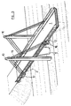
- FIG. 1 shows a bridge formed by an apron 1 carried by two lateral piers 2 and a central pier 3, and the ends of which rest on abutments 4.
- Two carriageways 5 each pass between the central pier 3 and a lateral pier 2, and leave between them a central reservation 6, inside which is placed the central pier 3.
- a ditch 7 passes between each carriageway 5 and a lateral pier 2.
- the land has a slope 8 close to a natural slope.
- Figures 2 and 3 show the structure after its transformation according to the method of the invention.
- lateral "ears" 12 which are concrete blocks, a cross section of which is given in FIG. 4.
- holes 13 slightly oblique with respect to the horizontal, that is to say they open out on the underside of the apron in the vicinity of the bulkhead of the apron 1, by diamond drilling of its median plane. These holes are preferably drilled in transverse planes symmetrical with respect to the median plane of the pile to be destroyed, and close to this plane.
- each lug 12 there are provided on the one hand cable passage channels 14 in extension of the holes 13, and on the other hand, channels 15, located in a plane parallel to the median plane of the deck 1, and oblique to the horizontal, that is to say directed towards the upper part of the corresponding pylon 10.
- the outlet of the channels 14 and 15 to the outside has been formed so as to serve as a fulcrum for anchoring heads 16, 17, for respectively prestressing cables 18 placed in the holes 13 and their extension 14, and on the other hand, for guy wires 19 which connect two ears 12 to each other on the same side of the deck, being deflected to the upper part of the corresponding pylon 10.
- the tensioning of the cables 18 and the stays 19 is advantageously carried out, at least in part, in a progressive and simultaneous manner, to avoid excessive stresses on the deck.
- the space is then cleared for setting the desired slope 20 of the land in the vicinity of the abutments 4, moving the ditch 7 into 21, and widening the pavement 5.
- the series of operations that have been described relates to a bridge whose deck is made of concrete.
- the invention also applies to the case where the bridge is, in whole or in part, metallic.
- the ears 12 can be metallic or concrete depending on the circumstances.
- transverse beam 23 is made of prestressed concrete or metal, and comprises, incorporated at its ends, anchoring points for the shrouds, as described above with regard to the ears 12.
Landscapes
- Architecture (AREA)
- Civil Engineering (AREA)
- Structural Engineering (AREA)
- Engineering & Computer Science (AREA)
- Bridges Or Land Bridges (AREA)
- Paper (AREA)
- Magnetic Resonance Imaging Apparatus (AREA)
- Dowels (AREA)
- Crystals, And After-Treatments Of Crystals (AREA)
- Stringed Musical Instruments (AREA)
- Diaphragms For Electromechanical Transducers (AREA)
- Heat Treatment Of Steel (AREA)
- Measurement Of Force In General (AREA)
- Measuring Fluid Pressure (AREA)
- Jib Cranes (AREA)
Claims (8)
- Verfahren zur Vergrößerung der Länge eines Feldes einer Brücke, die von einer von Widerlagern (4) und Pfeilern (2, 3) getragenen Brückentafel (1) gebildet ist, durch Entfernung mindestens eines Pfeilers (2),
dadurch gekennzeichnet, daß man folgende Arbeitsgänge vornimmt:a) Bau eines Pylons (10), der einen oberen Teil besitzt, der sich über dem Niveau der Brückentafel erstreckt,b) Anbringung oder Bildung eines Querträgers, "Wechselbalken" (18, 23) genannt, in einem geringen Abstand von der Spitze des Pfeilers, der zerstört werden soll, wobei der Wechselbalken unter der Brückentafel angeordnet ist oder deren unteren Teil durchquert,c) Anbringung mindestens eines Spannseils (19), das einen Punkt des oberen Teils des Pylons mit einem Punkt des Wechselbalkens verbindet,d) Unterspannungsetzen des oder der Spannseile (19), bis die vertikale Komponente der Kraft, die es bzw. sie auf den Wechselbalken ausüben, ungefähr gleich der vertikalen Reaktion des Pfeilers ist,e) Entfernung des Pfeilers (2). - Verfahren nach Anspruch 1, dadurch gekennzeichnet, daß der Wechselbalken aus mindestens einem Vorspannkabel (18) besteht, das sich von einem Rand der Brückentafel zum anderen und mindestens teilweise in Querrohren (13) erstreckt, die im unteren Teil der Brückentafel gebohrt sind.
- Verfahren nach Anspruch 1, dadurch gekennzeichnet, daß der Wechselbalken ein Querträger (23) aus Beton oder Metall ist, der unter der Brückentafel angeordnet ist.
- Verfahren nach einem der Ansprüche 1 bis 3, dadurch gekennzeichnet, daß man zwei Pylone (10) baut, und zwar einen auf jeder Seite der Tafel, und mindestens ein Spannseil (19) zwischen einem Punkt des oberen Teils eines auf einer Seite der Brückentafel gelegenen Pylons und einem auf derselben Seite der Brückentafel gelegenen Ende des Wechselbalkens anbringt.
- Verfahren nach einem der Ansprüche 1 bis 3, dadurch gekennzeichnet, daß man einen Pylon in der axialen Ebene der Brücke baut und mindestens ein Spannseil einen Punkt des oberen Teils des Pylons mit der Mitte des Wechselbalkens unter Durchquerung der Ebene der Oberseite der Brückentafel verbindet.
- Verfahren nach einem der Ansprüche 1 bis 5, dadurch gekennzeichnet, daß der Pylon in Nähe eines Pfeilers (3) angeordnet wird, der zwischen zwei Pfeilern (2), die entfernt werden sollen, bestehen bleiben soll, man einen Wechselbalken in Nähe jedes der Pfeiler, die zerstört werden sollen, anbringt, und die Spannseile die beiden Wechselbalken verbinden, indem sie im oberen Teil des Pylons umgelenkt werden.
- Verfahren nach einem der Ansprüche 1 bis 5, dadurch gekennzeichnet, daß der Pylon (10) in Nähe eines Widerlagers angeordnet wird und die Spannseile den Wechselbalken mit einem auf der entgegengesetzten Seite des Pylons gelegenen Gegengewicht verbinden, in dem sie an dessen oberen Teil umgelenkt werden.
- Verfahren nach den Ansprüchen 2 und 4 zusammen, in welchem die Brückentafel aus Beton besteht, dadurch gekennzeichnet, daß man vor der Anbringung des Wechselbalkens Verankerungsblöcke (12) aus Beton auf den beiden Rändern der Brückentafel bildet, die so geformt sind, daß sie die Verankerungspunkte der Enden (16, 17) der Vorspannungskabel (18) und der Spannseile (19) enthalten.
Applications Claiming Priority (2)
| Application Number | Priority Date | Filing Date | Title |
|---|---|---|---|
| FR9108157A FR2678654B1 (fr) | 1991-07-01 | 1991-07-01 | Procede pour elargir la portee d'une travee de pont. |
| FR9108157 | 1991-07-01 |
Publications (2)
| Publication Number | Publication Date |
|---|---|
| EP0521771A1 EP0521771A1 (de) | 1993-01-07 |
| EP0521771B1 true EP0521771B1 (de) | 1995-09-06 |
Family
ID=9414530
Family Applications (1)
| Application Number | Title | Priority Date | Filing Date |
|---|---|---|---|
| EP92401855A Expired - Lifetime EP0521771B1 (de) | 1991-07-01 | 1992-06-30 | Verfahren zum Erweitern eines Brückenfeldes |
Country Status (7)
| Country | Link |
|---|---|
| EP (1) | EP0521771B1 (de) |
| AT (1) | ATE127559T1 (de) |
| DE (1) | DE69204584T2 (de) |
| DK (1) | DK0521771T3 (de) |
| ES (1) | ES2079816T3 (de) |
| FR (1) | FR2678654B1 (de) |
| GR (1) | GR3017575T3 (de) |
Families Citing this family (20)
| Publication number | Priority date | Publication date | Assignee | Title |
|---|---|---|---|---|
| FR2735160B1 (fr) * | 1995-06-06 | 1997-08-29 | Razel Freres Entreprise | Procede pour augmenter la portee d'un pont. |
| FR2774710B1 (fr) * | 1998-02-09 | 2000-04-28 | Vsl France | Dispositif et procede pour permettre l'elimination d'une pile supportant le tablier d'un pont |
| CN101838969B (zh) * | 2010-02-09 | 2012-01-18 | 长沙理工大学 | 边跨散索套无支撑的独塔双跨自锚式悬索桥吊索张拉方法 |
| CN102121234B (zh) * | 2011-04-23 | 2012-04-04 | 中铁三局集团有限公司 | 一种双塔五跨钢桁梁斜拉桥的快速施工方法 |
| CN103233427B (zh) * | 2013-04-27 | 2015-04-22 | 长沙理工大学 | 一种双塔三跨平面主缆自锚式悬索桥吊索张拉与体系转换的方法 |
| CN105603890A (zh) * | 2015-11-16 | 2016-05-25 | 上海应用技术学院 | 矮塔斜拉式体外拉索加固梁式桥 |
| CN106012872B (zh) * | 2016-06-28 | 2019-03-12 | 山东大学 | 连续刚构桥的无背索斜拉加固体系及施工方法 |
| CN107245959B (zh) * | 2017-06-14 | 2018-11-30 | 暨南大学 | 一种双幅连续刚构桥的斜拉加固结构及其施工方法 |
| CN107119583A (zh) * | 2017-06-14 | 2017-09-01 | 沈阳建筑大学 | 一种双幅t型刚构桥背塔斜拉加固结构及其施工方法 |
| CN111155822A (zh) * | 2018-11-20 | 2020-05-15 | 中国船舶重工集团海装风电股份有限公司 | 用于风力发电机支撑塔架预应力结构的钢绞线安装方法 |
| CN109577173B (zh) * | 2019-01-03 | 2020-10-09 | 温州益德建设有限公司 | 一种市政桥梁墩座 |
| CN110318338B (zh) * | 2019-06-14 | 2021-01-05 | 中铁大桥局集团有限公司 | 一种安装定位钢锚梁的测量控制方法 |
| CN112832144B (zh) * | 2021-01-08 | 2021-12-07 | 重庆交通大学工程设计研究院有限公司 | 人行悬索桥加固结构及其施工工艺 |
| CN112878197A (zh) * | 2021-01-12 | 2021-06-01 | 中铁二局集团有限公司 | 一种斜拉桥混凝土横梁自承法现浇施工方法 |
| CN113174870B (zh) * | 2021-04-27 | 2022-12-02 | 郑州铁路职业技术学院 | 跨线天桥的墩位改造方法 |
| CN115492012B (zh) * | 2022-11-03 | 2025-05-23 | 中铁十九局集团第三工程有限公司 | 一种设有加宽增强结构的桥梁及施工方法 |
| CN116289649A (zh) * | 2023-03-06 | 2023-06-23 | 广州市市政工程设计研究总院有限公司 | 一种适用于混凝土桥塔的斜拉桥桥塔横向拼接改造的建造方法 |
| CN116892177B (zh) * | 2023-07-24 | 2026-04-14 | 广州市市政工程设计研究总院有限公司 | 一种旧桥错层拓宽设计方法 |
| CN117604930A (zh) * | 2023-12-27 | 2024-02-27 | 长安大学 | 一种跨线桥梁改造利用方法 |
| CN117926726B (zh) * | 2024-01-15 | 2026-03-17 | 中铁大桥勘测设计院集团有限公司 | 一种旧桥拓宽的施工方法及桥梁结构 |
Family Cites Families (3)
| Publication number | Priority date | Publication date | Assignee | Title |
|---|---|---|---|---|
| GB839413A (en) * | 1957-05-09 | 1960-06-29 | Ake Hedstroem | Improvements in or relating to bridges and other load-carrying structures |
| DE2754213B1 (de) * | 1977-12-06 | 1979-05-23 | Dyckerhoff & Widmann Ag | Verfahren zum Herstellen einer Zuegelgurtbruecke aus Stahl- oder Spannbeton |
| FR2619840B1 (fr) * | 1987-08-25 | 1990-01-19 | Muller International Jean | Pont de type haubane, et procede de construction d'un tel pont en remplacement d'un pont preexistant |
-
1991
- 1991-07-01 FR FR9108157A patent/FR2678654B1/fr not_active Expired - Fee Related
-
1992
- 1992-06-30 ES ES92401855T patent/ES2079816T3/es not_active Expired - Lifetime
- 1992-06-30 DK DK92401855.9T patent/DK0521771T3/da active
- 1992-06-30 DE DE69204584T patent/DE69204584T2/de not_active Expired - Fee Related
- 1992-06-30 EP EP92401855A patent/EP0521771B1/de not_active Expired - Lifetime
- 1992-06-30 AT AT92401855T patent/ATE127559T1/de not_active IP Right Cessation
-
1995
- 1995-09-29 GR GR950402379T patent/GR3017575T3/el unknown
Also Published As
| Publication number | Publication date |
|---|---|
| ES2079816T3 (es) | 1996-01-16 |
| FR2678654A1 (fr) | 1993-01-08 |
| DK0521771T3 (da) | 1995-10-23 |
| EP0521771A1 (de) | 1993-01-07 |
| DE69204584D1 (de) | 1995-10-12 |
| GR3017575T3 (en) | 1995-12-31 |
| ATE127559T1 (de) | 1995-09-15 |
| FR2678654B1 (fr) | 1993-09-24 |
| DE69204584T2 (de) | 1996-02-22 |
Similar Documents
| Publication | Publication Date | Title |
|---|---|---|
| EP0521771B1 (de) | Verfahren zum Erweitern eines Brückenfeldes | |
| EP1101871B1 (de) | Brückenoberbau aus Stahl und Verfahren zur Herstellung einer diesen Oberbau enthaltenden Brücke | |
| EP0340051B1 (de) | Brückentafel für eine Brücke mit grosser Spannweite | |
| EP0288350B1 (de) | Brücke, bestehend aus einem Deck und dessen Trägern, insbesondere Schrägseilbrücke und Verfahren zu ihrer Herstellung | |
| EP0463925B1 (de) | Verfahren zur Herstellung eines halbunterirdischen Bauwerks an einem Bergabhang und auf diese Weise hergestelltes Bauwerk | |
| FR2465835A1 (fr) | Procede de construction d'un pont a suspentes obliques ou a membrure bridee | |
| EP0329517B1 (de) | Schrägkabelbrücke und Verfahren zu deren Bau | |
| FR2749329A1 (fr) | Barriere de securite pour voies routieres et autoroutieres | |
| EP1337714B1 (de) | Schutzbarriere, insbesondere im gebirge | |
| FR2601051A1 (fr) | Support pour signal avertisseur routier, indicateur de direction, barrieres protectrices pedestres, et autres | |
| BE1001360A3 (fr) | Pont semi-prefabrique. | |
| FR2693492A1 (fr) | Pont haubanné et son procédé de réalisation. | |
| FR2619840A1 (fr) | Pont de type haubane, et procede de construction d'un tel pont en remplacement d'un pont preexistant | |
| FR2734287A1 (fr) | Pont a tablier en beton sans charpente metallique | |
| FR2662718A1 (fr) | Viaduc a trois voies. | |
| EP1119663B1 (de) | Rohrförmige anlage | |
| EP3115509B1 (de) | Verfahren zur herstellung und aufstellung eines bauwerks | |
| CH683540A5 (fr) | Barrage mobile de balisage et de signalisation. | |
| FR2653144A1 (fr) | Procede pour la construction d'ouvrages d'art sous les voies ferrees en exploitation. | |
| EP1418283A1 (de) | Modulare Trägerstruktur | |
| RU2199622C2 (ru) | Укрепление водоотводных сооружений | |
| FR2843977A1 (fr) | Procede de realisation d'une plate-forme enjambant une tranchee au moyen de longerons prefabriques | |
| FR3132111A1 (fr) | Elément préfabriqué en béton pour la construction d’un mur de soutènement | |
| FR2639377A1 (fr) | Pare-avalanche pour voies de circulation | |
| FR2774710A1 (fr) | Dispositif et procede pour permettre l'elimination d'une pile supportant le tablier d'un pont |
Legal Events
| Date | Code | Title | Description |
|---|---|---|---|
| PUAI | Public reference made under article 153(3) epc to a published international application that has entered the european phase |
Free format text: ORIGINAL CODE: 0009012 |
|
| 17P | Request for examination filed |
Effective date: 19920706 |
|
| AK | Designated contracting states |
Kind code of ref document: A1 Designated state(s): AT BE CH DE DK ES FR GB GR IT LI LU MC NL PT SE |
|
| 17Q | First examination report despatched |
Effective date: 19941102 |
|
| GRAA | (expected) grant |
Free format text: ORIGINAL CODE: 0009210 |
|
| RAP1 | Party data changed (applicant data changed or rights of an application transferred) |
Owner name: ENTREPRISE RAZEL FRERES, SOCIETE ANONYME DITE: |
|
| AK | Designated contracting states |
Kind code of ref document: B1 Designated state(s): AT BE CH DE DK ES FR GB GR IT LI LU MC NL PT SE |
|
| REF | Corresponds to: |
Ref document number: 127559 Country of ref document: AT Date of ref document: 19950915 Kind code of ref document: T |
|
| REF | Corresponds to: |
Ref document number: 69204584 Country of ref document: DE Date of ref document: 19951012 |
|
| REG | Reference to a national code |
Ref country code: DK Ref legal event code: T3 |
|
| ITF | It: translation for a ep patent filed | ||
| GBT | Gb: translation of ep patent filed (gb section 77(6)(a)/1977) |
Effective date: 19951017 |
|
| REG | Reference to a national code |
Ref country code: GR Ref legal event code: FG4A Free format text: 3017575 |
|
| SC4A | Pt: translation is available |
Free format text: 950921 AVAILABILITY OF NATIONAL TRANSLATION |
|
| REG | Reference to a national code |
Ref country code: ES Ref legal event code: FG2A Ref document number: 2079816 Country of ref document: ES Kind code of ref document: T3 |
|
| PLBE | No opposition filed within time limit |
Free format text: ORIGINAL CODE: 0009261 |
|
| STAA | Information on the status of an ep patent application or granted ep patent |
Free format text: STATUS: NO OPPOSITION FILED WITHIN TIME LIMIT |
|
| 26N | No opposition filed | ||
| PGFP | Annual fee paid to national office [announced via postgrant information from national office to epo] |
Ref country code: DK Payment date: 19990629 Year of fee payment: 8 Ref country code: AT Payment date: 19990629 Year of fee payment: 8 |
|
| PGFP | Annual fee paid to national office [announced via postgrant information from national office to epo] |
Ref country code: NL Payment date: 19990630 Year of fee payment: 8 Ref country code: GR Payment date: 19990630 Year of fee payment: 8 Ref country code: SE Payment date: 19990630 Year of fee payment: 8 Ref country code: ES Payment date: 19990630 Year of fee payment: 8 |
|
| PGFP | Annual fee paid to national office [announced via postgrant information from national office to epo] |
Ref country code: PT Payment date: 19990706 Year of fee payment: 8 |
|
| PGFP | Annual fee paid to national office [announced via postgrant information from national office to epo] |
Ref country code: MC Payment date: 19990712 Year of fee payment: 8 |
|
| PGFP | Annual fee paid to national office [announced via postgrant information from national office to epo] |
Ref country code: GB Payment date: 19990713 Year of fee payment: 8 |
|
| PGFP | Annual fee paid to national office [announced via postgrant information from national office to epo] |
Ref country code: BE Payment date: 19990730 Year of fee payment: 8 |
|
| PGFP | Annual fee paid to national office [announced via postgrant information from national office to epo] |
Ref country code: DE Payment date: 19990806 Year of fee payment: 8 |
|
| PGFP | Annual fee paid to national office [announced via postgrant information from national office to epo] |
Ref country code: LU Payment date: 19990810 Year of fee payment: 8 |
|
| PGFP | Annual fee paid to national office [announced via postgrant information from national office to epo] |
Ref country code: CH Payment date: 19990916 Year of fee payment: 8 |
|
| PG25 | Lapsed in a contracting state [announced via postgrant information from national office to epo] |
Ref country code: MC Free format text: THE PATENT HAS BEEN ANNULLED BY A DECISION OF A NATIONAL AUTHORITY Effective date: 20000630 Ref country code: LU Free format text: LAPSE BECAUSE OF NON-PAYMENT OF DUE FEES Effective date: 20000630 Ref country code: LI Free format text: LAPSE BECAUSE OF NON-PAYMENT OF DUE FEES Effective date: 20000630 Ref country code: GR Free format text: LAPSE BECAUSE OF NON-PAYMENT OF DUE FEES Effective date: 20000630 Ref country code: GB Free format text: LAPSE BECAUSE OF NON-PAYMENT OF DUE FEES Effective date: 20000630 Ref country code: DK Free format text: LAPSE BECAUSE OF NON-PAYMENT OF DUE FEES Effective date: 20000630 Ref country code: CH Free format text: LAPSE BECAUSE OF NON-PAYMENT OF DUE FEES Effective date: 20000630 Ref country code: BE Free format text: LAPSE BECAUSE OF NON-PAYMENT OF DUE FEES Effective date: 20000630 Ref country code: AT Free format text: LAPSE BECAUSE OF NON-PAYMENT OF DUE FEES Effective date: 20000630 |
|
| PG25 | Lapsed in a contracting state [announced via postgrant information from national office to epo] |
Ref country code: SE Free format text: LAPSE BECAUSE OF NON-PAYMENT OF DUE FEES Effective date: 20000701 Ref country code: ES Free format text: THE PATENT HAS BEEN ANNULLED BY A DECISION OF A NATIONAL AUTHORITY Effective date: 20000701 |
|
| BERE | Be: lapsed |
Owner name: ENTREPRISE RAZEL FRERES Effective date: 20000630 |
|
| PG25 | Lapsed in a contracting state [announced via postgrant information from national office to epo] |
Ref country code: PT Free format text: LAPSE BECAUSE OF NON-PAYMENT OF DUE FEES Effective date: 20001231 |
|
| PG25 | Lapsed in a contracting state [announced via postgrant information from national office to epo] |
Ref country code: NL Free format text: LAPSE BECAUSE OF NON-PAYMENT OF DUE FEES Effective date: 20010101 |
|
| REG | Reference to a national code |
Ref country code: CH Ref legal event code: PL |
|
| GBPC | Gb: european patent ceased through non-payment of renewal fee |
Effective date: 20000630 |
|
| REG | Reference to a national code |
Ref country code: DK Ref legal event code: EBP |
|
| NLV4 | Nl: lapsed or anulled due to non-payment of the annual fee |
Effective date: 20010101 |
|
| EUG | Se: european patent has lapsed |
Ref document number: 92401855.9 |
|
| PG25 | Lapsed in a contracting state [announced via postgrant information from national office to epo] |
Ref country code: DE Free format text: LAPSE BECAUSE OF NON-PAYMENT OF DUE FEES Effective date: 20010403 |
|
| REG | Reference to a national code |
Ref country code: PT Ref legal event code: MM4A Free format text: LAPSE DUE TO NON-PAYMENT OF FEES Effective date: 20001231 |
|
| REG | Reference to a national code |
Ref country code: ES Ref legal event code: FD2A Effective date: 20020204 |
|
| PG25 | Lapsed in a contracting state [announced via postgrant information from national office to epo] |
Ref country code: IT Free format text: LAPSE BECAUSE OF NON-PAYMENT OF DUE FEES Effective date: 20050630 |
|
| PGFP | Annual fee paid to national office [announced via postgrant information from national office to epo] |
Ref country code: FR Payment date: 20110321 Year of fee payment: 20 |