EP0521831A1 - Hin- und herbewegbare Antriebsvorrichtung, insbesondere für den Wischarm für die Heckscheibe eines Motorfahrzeuges - Google Patents
Hin- und herbewegbare Antriebsvorrichtung, insbesondere für den Wischarm für die Heckscheibe eines Motorfahrzeuges Download PDFInfo
- Publication number
- EP0521831A1 EP0521831A1 EP92830327A EP92830327A EP0521831A1 EP 0521831 A1 EP0521831 A1 EP 0521831A1 EP 92830327 A EP92830327 A EP 92830327A EP 92830327 A EP92830327 A EP 92830327A EP 0521831 A1 EP0521831 A1 EP 0521831A1
- Authority
- EP
- European Patent Office
- Prior art keywords
- motor
- supply
- electrically
- inverter
- wiper arm
- Prior art date
- Legal status (The legal status is an assumption and is not a legal conclusion. Google has not performed a legal analysis and makes no representation as to the accuracy of the status listed.)
- Withdrawn
Links
Images



Classifications
-
- B—PERFORMING OPERATIONS; TRANSPORTING
- B60—VEHICLES IN GENERAL
- B60S—SERVICING, CLEANING, REPAIRING, SUPPORTING, LIFTING, OR MANOEUVRING OF VEHICLES, NOT OTHERWISE PROVIDED FOR
- B60S1/00—Cleaning of vehicles
- B60S1/02—Cleaning windscreens, windows or optical devices
- B60S1/04—Wipers or the like, e.g. scrapers
- B60S1/06—Wipers or the like, e.g. scrapers characterised by the drive
- B60S1/08—Wipers or the like, e.g. scrapers characterised by the drive electrically driven
Definitions
- the present invention relates to a reciprocating drive device, particularly for driving a wiper arm for the rear window of a motor vehicle.
- Known reciprocating drive devices for front and rear windscreen wipers of a motor vehicle include direct-current electric motors which are always rotated in the same sense.
- the rotary motion of the shaft of the electric motor is converted into a reciprocating motion by a kinematic mechanism which typically includes connecting rods and cranks.
- An object of the present invention is to provide a drive device in which the reciprocating rotary motion of an output shaft is achieved electrically rather than mechanically, without the need to use any of the kinematic mechanisms used in conventional devices, and which requires a minimal number of electrical connecting wires.
- a reciprocating drive device particularly for a wiper arm, including in combination:
- a device includes a direct-current electric motor with permanent magnets.
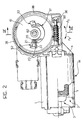
- the motor indicated M in Figures 1 and 2, includes, in known manner, a casing 1, a stator 2 with permanent magnets, and a rotor 3 ( Figure 2).
- the motor M has a first brush m1 which is connected to the first of two supply terminals, indicated 10 and 11.
- a bifilar connection 12 connects the supply terminals to the output side of an inverter 13, the input side of which is connected to a direct-current voltage supply 14, such as the battery of a motor vehicle.
- the inverter 13, which is of known type, can assume a first condition in which it connects the terminals 10 and 11 to the positive and negative poles of the supply 14, respectively, and a second condition in which it connects the supply terminals 10, 11 to the negative and positive poles of the supply, respectively.
- a control device 15 can switch the inverter 13 at a predetermined frequency when a manual control switch I is closed.
- An electromechanical device for controlling the supply to the motor M is indicated C. This device is connected electrically to the brushes of the motor M and to the supply terminals 10 and 11.
- the electromechanical device for controlling the supply to the motor includes a disc-shaped member 61 which is rotatable in a support casing 36 fixed to the casing 1 of the electric motor M.
- a worm screw 60 connected to the shaft of the motor meshes, within the casing 36, with outer teeth on the disc-shaped member 61.
- a shaft (indicated 62 in Figure 3) fixed to the centre of the disc 61 constitutes the output shaft of the drive device as a whole.
- One end 63 of the shaft projects from the support casing 36 and a wiper arm 64 (shown partially in Figure 3), which can be used, for example, to wipe the rear window of a motor vehicle, can be connected thereto in known manner.
- the disc-shaped element 61 is made of an electrically-insulating material and one of its faces has metallised portions which define a main electrically-conductive surface S1 and two auxiliary electrically-conductive surfaces S2 and S3 ( Figure 2).
- the face of the disc 61 which carries the electrically-conductive surfaces is shown as a linear development, and is thus substantially rectangular, in Figure 1.
- four contact members indicated 20 to 23, have respective first ends which are fixed (in known manner, not shown) to the support casing 36, their other ends being in frontal contact with the surface of the member 61.
- the sliding contacts 20 and 21, which will be referred to below as the main contacts, are connected respectively to the supply terminal 11 and to the brush m2 of the electric motor M.
- the anode of the diode D3 is connected to the fixed contact 22 and its cathode is connected to the supply terminal 10.
- the anode of the diode D4 is connected to the supply terminal 10 and its cathode is connected to the sliding contact 23.
- the motor M when the motor M is activated, it may rotate the disc 61 in the sense indicated by the the arrow F1 or in the sense indicated by the arrow F2, according to the polarity of the voltage applied thereto.
- the surface S1 is elongate and has two end extensions 40 and 41.
- the extensions are in positions such that they can be engaged solely by the sliding contact 20 whereas the rest of the surface S1 can be engaged by both the sliding contacts 20 and 21.
- the auxiliary electrically-conductive surface S2 is substantially C-shaped and has a side arm 42 which is adjacent the extension 40 of the surface S1 so as to be engaged solely by the sliding contact 21. Between the ends of the arm 42 of S2 and S1, there is a narrow space 43 large enough to ensure electrical insulation between S′1 and S′1 but preferably smaller than the effective contact area of the sliding contact 21.
- the electrically-conductive surface S2 also has a second, shorter arm, indicated 44, which is parallel to the arm 42.
- the arm 44 is positioned so that it can be engaged solely by the sliding contact 23.
- the arms 42 and 44 of the surface S2 are joined by a transverse arm 45 which has the function of connecting the side arms but is not intended to be engaged by a sliding contact.
- the electrically-conductive surface S3 is shaped substantially like an inverted L, having an arm 46 for engagement by the sliding contact 21 and an arm 47 for engagement by the sliding contact 22.
- the arm 46 of S3 is separated from S1 by a narrow space 48 which is wide enough to ensure the insulation of S′1 and S′3 but is preferably smaller than the effective contact area of the sliding contact 21.
- Two semiconductor diodes carried by the element 61 are indicated D1 and D2.
- the anode of the diode D1 is connected to S1 and its cathode is connected to S2, and the anode of the diode D2 is connected to S3 and its cathode to S1.
- the device described above adopts the configuration shown in Figure 1 (position a).
- the main sliding contacts 20 and 21 engage the appendage 40 of S1 and the side arm 42 of S2, respectively.
- the sliding contact 22 touches the surface of the movable element 61 without engaging an electrically-conductive surface, and the sliding contact 23 engages the arm 44 of S2.
- the supply 14 is connected to the inverter 13 and the control device 15 arranges the inverter in one of its possible conditions described above. If the inverter 13 connects the positive pole of the supply 14 to the supply terminal 11 and its negative pole to the supply terminal 10, as shown in Figure 1, the motor M is activated as a result of the passage of a current through the sliding contact 20, the surface S1, the diode D1, the surface S2, the sliding contact 21 and then through the motor M.
- the operation of the motor M moves the wiper arm 64 and the member 61 associated therewith in the direction indicated by the arrow F1. After it has performed a certain movement in this direction, the sliding contacts reach the positions, relative to the member 61, corresponding to the line b in Figure 1; the sliding contact 20 continues to engage S1 but the contact 21, which has left the arm 42 of S2, also touches S1. In this condition, the motor continues to be rotated, still in the original sense, as a result of the passage of the current through the sliding contact 20, the surface S1, the contact 21 and then through the motor M. The wiper arm 64 continues to move in the original sense. The member 61 continues to move in the direction indicated by the arrow F1.
- the wiper arm and the member 61 continue to move until the sliding contacts reach the position indicated c in Figure 1, relative to the member 61.
- the control device 15 is arranged to reverse the connections between the supply terminals 10 and 11 and the poles of the supply 14 at this point.
- the switching frequency of the inverter 13 must correspond to a period substantially equal to the time needed for the member 61 to perform an outward or return stroke, the outward stroke corresponding to the distance the member has to travel in order for the sliding contacts 20 and 23 to move from the position indicated a in Figure 1 to the position indicated d.
- the device can nevertheless operate if the switching frequency of the inverter 13 corresponds to a period shorter than the nominal time needed for an outward or return stroke of the member 61 and for the wiper arm 64 to pivot through the whole of the predetermined wiping angle.
- the supply terminals 10 and 11 are connected respectively to the positive and negative poles of the supply 14 the flow of current through the motor, the sliding contact 21, the electrically-conductive surface S3, the diode D2, the surface S1, the sliding contact 20 and the supply terminal 11 causes the motor M to rotate in the opposite sense from that in which it rotated previously.
- the movable contact 61 thus starts its return stroke, moving in the direction indicated by the arrow F2.
- the motor M When the sliding contact 21 is disengaged from the electrically-conductive surface S3 and engages the surface S1, the motor M continues to rotate in the same sense. In fact, the current can flow from the input terminal 10 to the terminal 11 through the motor M, the sliding contact 21, the surface S1 and the sliding contact 20.
- the wiper arm and the member 61 continue to move in the direction indicated by the arrow F2 until the sliding contact 21 leaves S1 and comes into contact with the arm 42 of S2. In this condition, the supply of current to the motor M is cut off. Immediately afterwards, as soon as the sliding contact 23 engages S2, the motor M is short-circuited through the conductive path including D4, the sliding contact 23, the surface S2 and the sliding contact 21. The motor M is braked abruptly.
- the device 15 switches the inverter 13 again and the device continues to operate in the manner described above.
- the device can therefore operate even if the switching frequency of the inverter 13 corresponds to a period shorter than the nominal time needed for an outward or return stroke of the member 61 and for the arm 64 to pivot through the entire predetermined wiping angle.
- the device described above may conveniently be used for driving the wiper arm associated with the rear window of a motor vehicle.
- the inverter 13 and the control device 15 may conveniently be located in the front portion of the vehicle, for example, near the dashboard, and may be connected to the rest of the device, that is, to the electromechanical device C and to the motor M by means of only two connecting wires, that is, by the bifilar connection indicated 12 in Figure 1. This characteristic is particularly convenient.
- Figure 4 of the appended drawings shows a variant in which the surface S2 is substantially L-shaped and the surface S3 is substantially C-shaped.
- the short-circuiting and braking of the motor M are achieved at one end of the stroke by the engagement of the sliding contact 23 on the arm of S3 which is indicated 50 in Figure 4.
Landscapes
- Engineering & Computer Science (AREA)
- Mechanical Engineering (AREA)
- Control Of Direct Current Motors (AREA)
- Power-Operated Mechanisms For Wings (AREA)
Applications Claiming Priority (2)
| Application Number | Priority Date | Filing Date | Title |
|---|---|---|---|
| ITTO910514A IT1250197B (it) | 1991-07-03 | 1991-07-03 | Dispositivo di comando a moto alternativo, in particolare per il braccio tergitore per il lunotto posteriore di un autoveicolo |
| ITTO910514 | 1991-07-03 |
Publications (1)
| Publication Number | Publication Date |
|---|---|
| EP0521831A1 true EP0521831A1 (de) | 1993-01-07 |
Family
ID=11409461
Family Applications (1)
| Application Number | Title | Priority Date | Filing Date |
|---|---|---|---|
| EP92830327A Withdrawn EP0521831A1 (de) | 1991-07-03 | 1992-06-23 | Hin- und herbewegbare Antriebsvorrichtung, insbesondere für den Wischarm für die Heckscheibe eines Motorfahrzeuges |
Country Status (2)
| Country | Link |
|---|---|
| EP (1) | EP0521831A1 (de) |
| IT (1) | IT1250197B (de) |
Cited By (1)
| Publication number | Priority date | Publication date | Assignee | Title |
|---|---|---|---|---|
| EP0788949A1 (de) * | 1996-02-08 | 1997-08-13 | Robert Bosch Gmbh | Anschluss eines Regensensor-Steuergerätes an den Fahrzeugkabelbaum |
Citations (6)
| Publication number | Priority date | Publication date | Assignee | Title |
|---|---|---|---|---|
| FR2443161A1 (fr) * | 1978-11-30 | 1980-06-27 | Rau Swf Autozubehoer | Circuit pour moteur electrique d'entrainement a sens de rotation inversable, alimente par une source de tension |
| DE2942739A1 (de) * | 1979-10-23 | 1981-05-07 | SWF-Spezialfabrik für Autozubehör Gustav Rau GmbH, 7120 Bietigheim-Bissingen | Schaltanordnung fuer eine pendelwischanlage |
| DE3008580A1 (de) * | 1980-03-06 | 1981-09-17 | Westfälische Metall Industrie KG Hueck & Co, 4780 Lippstadt | Vorrichtung zum steuern einer scheibenwischeinrichtung fuer kraftfahrzeuge |
| DE3044011A1 (de) * | 1980-11-22 | 1982-06-24 | SWF-Spezialfabrik für Autozubehör Gustav Rau GmbH, 7120 Bietigheim-Bissingen | Heckwischeranlage fuer kraftfahrzeuge |
| DE3042019A1 (de) * | 1979-10-23 | 1982-06-24 | SWF-Spezialfabrik für Autozubehör Gustav Rau GmbH, 7120 Bietigheim-Bissingen | Schaltanordnung fuer eine pendelwischanlage |
| EP0279786A1 (de) * | 1987-01-28 | 1988-08-24 | INDUSTRIE MAGNETI MARELLI S.p.A. | Wischervorrichtung für Windschutz- oder Heckscheibe, insbesondere für ein Kraftfahrzeug |
-
1991
- 1991-07-03 IT ITTO910514A patent/IT1250197B/it active IP Right Grant
-
1992
- 1992-06-23 EP EP92830327A patent/EP0521831A1/de not_active Withdrawn
Patent Citations (6)
| Publication number | Priority date | Publication date | Assignee | Title |
|---|---|---|---|---|
| FR2443161A1 (fr) * | 1978-11-30 | 1980-06-27 | Rau Swf Autozubehoer | Circuit pour moteur electrique d'entrainement a sens de rotation inversable, alimente par une source de tension |
| DE2942739A1 (de) * | 1979-10-23 | 1981-05-07 | SWF-Spezialfabrik für Autozubehör Gustav Rau GmbH, 7120 Bietigheim-Bissingen | Schaltanordnung fuer eine pendelwischanlage |
| DE3042019A1 (de) * | 1979-10-23 | 1982-06-24 | SWF-Spezialfabrik für Autozubehör Gustav Rau GmbH, 7120 Bietigheim-Bissingen | Schaltanordnung fuer eine pendelwischanlage |
| DE3008580A1 (de) * | 1980-03-06 | 1981-09-17 | Westfälische Metall Industrie KG Hueck & Co, 4780 Lippstadt | Vorrichtung zum steuern einer scheibenwischeinrichtung fuer kraftfahrzeuge |
| DE3044011A1 (de) * | 1980-11-22 | 1982-06-24 | SWF-Spezialfabrik für Autozubehör Gustav Rau GmbH, 7120 Bietigheim-Bissingen | Heckwischeranlage fuer kraftfahrzeuge |
| EP0279786A1 (de) * | 1987-01-28 | 1988-08-24 | INDUSTRIE MAGNETI MARELLI S.p.A. | Wischervorrichtung für Windschutz- oder Heckscheibe, insbesondere für ein Kraftfahrzeug |
Non-Patent Citations (1)
| Title |
|---|
| PATENT ABSTRACTS OF JAPAN vol. 12, no. 478 (M-775)(3325) 14 December 1988 & JP-A-63 199 157 ( MITSUBISHI CABLE ) 17 August 1988 * |
Cited By (1)
| Publication number | Priority date | Publication date | Assignee | Title |
|---|---|---|---|---|
| EP0788949A1 (de) * | 1996-02-08 | 1997-08-13 | Robert Bosch Gmbh | Anschluss eines Regensensor-Steuergerätes an den Fahrzeugkabelbaum |
Also Published As
| Publication number | Publication date |
|---|---|
| ITTO910514A1 (it) | 1993-01-03 |
| IT1250197B (it) | 1995-04-03 |
| ITTO910514A0 (it) | 1991-07-03 |
Similar Documents
| Publication | Publication Date | Title |
|---|---|---|
| US3689817A (en) | Windshield wiper system | |
| JPH03500960A (ja) | 駆動機構、特に車の風防用のワイパーシステム | |
| JPH035261A (ja) | ワイパーおよびワイパー駆動機構 | |
| KR900000517B1 (ko) | 2방향으로 회전하는 모우터를 사용한 와이퍼장치의 제어장치 | |
| US4599546A (en) | Wiper device | |
| US5654616A (en) | Windshield wiper system with soft wipe mode for high speed operation | |
| JPS6048370B2 (ja) | ワイパ−装置 | |
| GB2052099A (en) | Control of wiper drive | |
| US3579067A (en) | Motor control system | |
| JPS61155041A (ja) | 自動車用窓ふき装置 | |
| EP0524914A1 (de) | Hin- und herbewegende Antriebsvorrichtung, besonders für einen Heckscheibenwischer eines Motorfahrzeugs | |
| CN1201950C (zh) | 接触盘系统和玻璃刮水器电机的控制方法 | |
| US5861723A (en) | Windscreen wiper device | |
| US1608985A (en) | Motor-control system for electrically-operated windshield cleaners | |
| CN101983146A (zh) | 具有双稳态继电器的刮水器换向电子装置 | |
| KR100688043B1 (ko) | 윈드실드 와이퍼 장치 | |
| KR960008344B1 (ko) | 전동식 동력조향장치 | |
| JP4079694B2 (ja) | ワイパ装置 | |
| CN1205072C (zh) | 接触盘系统和玻璃刮水器电机的控制方法 | |
| JPS5853245Y2 (ja) | 遮へい式ワイパ装置 | |
| JPS6325248Y2 (de) | ||
| EP0279786B1 (de) | Wischervorrichtung für Windschutz- oder Heckscheibe, insbesondere für ein Kraftfahrzeug | |
| JP2004148896A (ja) | ワイパ装置 | |
| JP2953148B2 (ja) | 車両用リヤワイパ装置 | |
| JPH0139092Y2 (de) |
Legal Events
| Date | Code | Title | Description |
|---|---|---|---|
| PUAI | Public reference made under article 153(3) epc to a published international application that has entered the european phase |
Free format text: ORIGINAL CODE: 0009012 |
|
| AK | Designated contracting states |
Kind code of ref document: A1 Designated state(s): DE ES FR GB SE |
|
| 17P | Request for examination filed |
Effective date: 19930310 |
|
| 17Q | First examination report despatched |
Effective date: 19940210 |
|
| 18D | Application deemed to be withdrawn |
Effective date: 19940621 |