EP0521834B1 - Vorrichtung zum Festlegen von Rädern von Fahrzeugen auf einem für ihren Transport benutzten Eisenbahnwaggon - Google Patents
Vorrichtung zum Festlegen von Rädern von Fahrzeugen auf einem für ihren Transport benutzten Eisenbahnwaggon Download PDFInfo
- Publication number
- EP0521834B1 EP0521834B1 EP92830343A EP92830343A EP0521834B1 EP 0521834 B1 EP0521834 B1 EP 0521834B1 EP 92830343 A EP92830343 A EP 92830343A EP 92830343 A EP92830343 A EP 92830343A EP 0521834 B1 EP0521834 B1 EP 0521834B1
- Authority
- EP
- European Patent Office
- Prior art keywords
- holes
- rod
- handle
- locking
- plate
- Prior art date
- Legal status (The legal status is an assumption and is not a legal conclusion. Google has not performed a legal analysis and makes no representation as to the accuracy of the status listed.)
- Expired - Lifetime
Links
Images

Classifications
-
- B—PERFORMING OPERATIONS; TRANSPORTING
- B61—RAILWAYS
- B61D—BODY DETAILS OR KINDS OF RAILWAY VEHICLES
- B61D45/00—Means or devices for securing or supporting the cargo, including protection against shocks
- B61D45/001—Devices for fixing to walls or floors
-
- B—PERFORMING OPERATIONS; TRANSPORTING
- B61—RAILWAYS
- B61D—BODY DETAILS OR KINDS OF RAILWAY VEHICLES
- B61D3/00—Wagons or vans
- B61D3/16—Wagons or vans adapted for carrying special loads
- B61D3/18—Wagons or vans adapted for carrying special loads for vehicles
- B61D3/187—Details, e.g. bridges for floor connections
- B61D3/188—Wheel guides for the vehicles being carried
Definitions
- the present invention relates to the field of railroad equipment and more precisely to an improved device for locking the wheels of vehicles on a railroad car used for their transport.
- a first embodiment of said prior device comprises a rod which can be fixed in one of said grooves and a substantially tubular sliding guide on said rod, on which a support plate for the stopping means of the wheel of the vehicle to be locked is provided.
- Said stopping means is inclined with respect to the track of the wheel, so that, to lock the latter on the platform of the railroad car, it is sufficient to introduce the rod into the groove closest to the track of the wheel and move the plate along the rod by means of the guide which slides in the groove until the stopping means meets the wheel. At this point, to fix the position of the stopping means with respect to the wheel it is sufficient to introduce a protruding pin of the guide into one of the several longitudinal holes formed in the rod.
- the device according to this first embodiment is very simple to construct and to utilize, in that it requires only one adjustment in a direction transversal to the wheel.
- the device is suitable only for light vehicles, such as automobiles, and it is not proper for heavier vehicles, such as trucks, for which the forces derived from braking or curving of the train are significantly greater.
- the device has two adjustments, one in a transversal direction similar to the previous one, and one in a longitudinal direction obtained by means of a mobile plate carrying the stopping means and a fixed plate integral with a tubular guide and in which the mobile plate slides.
- the position of the fixed plate with respect to the mobile one is adjustable by means of a pair of hooks which are introduced into a pair of holes created in the fixed plate and in holes placed along two rows formed in the mobile plate.
- the device is then fixed in the groove closest to the track of the wheel, then its position is adjusted first in a transversal direction as previously described, and then in a longitudinal direction, until the stopping means meets the wheel.
- the two adjustments are independent and must be carried out separately, requiring increased positioning time of the device for each wheel and a greater difficulty in manoeuvrability.
- the stopping means of the device according to the above cited prior patent application has been proven inadequate, in that the mobile plate, pressed by loads which burden the stopping means itself, sometimes becomes deformed permanently and the device is damaged.
- the object of the present invention is to provide an improved device for locking the wheels of vehicles on a railroad car used for their transport which is easy to construct, of simple, easy and safe manoeuvrability from the stand point of the workmen, and which is sturdy and load resistant without deformations in its structure.
- the locking device is suited for locking the wheels of vehicles on a railroad car used for their transport and having a platform with parallel transversal grooves, and comprises, in common with the locking device according to prior filed EP-A-0 442 245, stopping means for one of the wheels of the vehicles, a rod, with a plurality of longitudinally spaced holes, which can be fitted in one of the grooves and a guide which slides on said rod and is integral with a base with which a support element for the stopping means of the wheel engages slidingly.
- the support element for the stopping means comprises an elongate structure with box-type ends to one of which the stopping means is fixed and a plate, which guides the sliding of the base, said plate extending in fixed relation between said ends and provided, in the middle part comprised between said ends, with a plurality of holes.
- Retractable locking means engageable contemporaneously with the plate of the support element, the base and the rod are provided for in order to lock with a single manoeuvre the relative movements.
- a stopping equipment for said mobile locking means is provided for.
- the device according to the invention has the advantage of easy adjustment of the position with respect to the wheel and of increased sturdiness under heavy loads.
- the advantage of easy manoeuvrability is very important, mainly taking into account the number of operations of this type which the railroad workmen assigned to the locking and releasing of wheels of vehicles on railroad car platforms carry out for a train load.
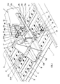
- 1 generally indicates a transversal portion of a lane of a platform of a railroad car of a known type, for the transport of various types of vehicles.
- the lane has longitudinal external 2 and internal 3 edges and is made in fretted sheet, comprising a plurality of transversal grooves 4 delimitated by corresponding projections 5 on each of which there is formed a row of holes 6 drawn towards outerside with a sharp edge in order to increase the adherence of the tires to the platform itself.
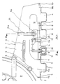
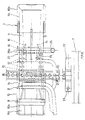
- the above mentioned figures also illustrate the improved device for the locking of the wheel R of a vehicle, indicated generically by 7, comprising stopping means 8 and 9 for said wheel fixed to an elongate support element 10 with box-type ends 10a and 10b to which there are fixed the ends 11a and 11b of a substantially rectangular plate 11 with a central part raised in a longitudinal direction and provided with holes 12, in the central middle portion, which are positioned in two rows illustrated with dashed lines in figure 4.
- the lower central portion of the element 10 has a wide opening 13 in which an internally hollow base 14 is slidingly engaged with the middle portion of the plate 11 which is suspended between its two ends 11a and 11b.
- Mobile locking means with the element 10 and the platform 1 as well as a stopping equipment of the mobile locking means are fixed to the base 14.
- two flat supports 15, having an elongated circular hole 15a in which a tubular sleeve 16 is slidingly and rotationally engaged are fastened in a protruding way to the base 14 on the side facing the end 11b of the plate 11.
- a flat arm 17 is fastened with one end to the tubular sleeve 16 and has at the other end a forked pin 18.
- a laterally bent projection 17a extending orthogonally to the latter is provided for.
- To the lower face of the base 14 a tubular guide 19 in which a channel section rod 20 is slidingly engaged is fastened.
- the channel section rod 20 has a plurality of equally spaced holes 21 made in its horizontal wall and is provided with a projecting plate 22 positioned orthogonally to the rod 20 itself and comprising a pin 23 engageable with one of the holes 6 of the platform 1.
- the forked pin 18 in figure 1 is shown with its ends introduced in two holes 24 formed on the upper face and, correspondingly, on the lower face of the base 14, as well as in a pair of holes 12 formed on the plate 11 and in a pair of holes 21 of the rod 20.
- a tubular manoeuvring handle is also illustrated which is bent substantially in a L-shape, one end 25a of which is suited to be grasped by a user, while the other end 25b is slidingly engaged in the tubular sleeve 16 and has at its end a shoulder 27 against which one end of a spring 28 operates while the other end of the spring urges against the sleeve 17.
- the handle 25 also has a pivot 29, bent at right angle which can engage with an open seat 30 formed in one of the flat supports 15 and with a saddle seat 26 formed in the projection 17a which extends from the arm 17.
- an auxiliary gripping handle 31 fastened on a side face of the support element 10 is provided for.
- the locking device 7 is prevented from being separated from the rod 20 by means of a hook 20a, fixed to one end of the rod, and the projecting plate 22, fixed to its other end, preventing complete extraction of the rod from the guide 19 which is integral with the device 7 and in which the rod 20 itself slides.
- the pin 23 is introduced into one of the holes 6 of the platform 1 and contemporaneously the rod 20 and the tubular guide 19, in which the rod 20 slides, are placed in the groove 4 of the platform itself.
- the chosen groove 4, and therefore the row of holes 6, is that which is closest to the track of the wheel R which must be locked.
- the positioning of the stopping means 8 and 9 against the track and a side face of the wheel R is carried out by pulling the spring loaded handle 25 until the shoulder 27 compresses the spring 28 against one of the enlarged edges of the sleeve 16 and, therefore, until the right-angled pivot 29 disengages the seat 30 and allows for the rotation of the handle 25.
- the next step is to release the handle 25 itself which, under the force of the spring 28, returns to a resting position pulling the right-angled pivot 29 back to the seat 30 of the supports 15 and thus preventing accidental rotation of the handle 25.
- the hole 15a of the flat supports 15 is elongated in order to allow the pin 18 to be entered or extracted from the holes 12, 24 and 21 because the axes of these holes do not lie on the circular trajectory that the pin 18 should follow.
- the locking device 7 therefore requires, as described above, a single manoeuvre to carry out the operations of positioning the stopping means 8 and 9 against the wheel resting on the platform. Furthermore the box-type form of the support element 10 and the presence of the plate 11 allow for a better and more strong distribution of the load which is derived from the sharp movements of the railroad car on which the platform 1 is mounted. Infact, the load burdening the stopping means 8 and 9 is distributed on the lower faces of the ends 10a and 10b of the support element 10, which rests on the numerous drawn holes 6 of the projections 5 of the platform 1.
- the device described above has been proven efficient also in the case of ice formation and dirt deposits and incrustations, in particular in correspondence with the pin 18. This is due to the length of the arm 25a which allows, with a not very strong force, the extraction of the fork 18 from the holes with which it is engaged even in these cases of greater resistance.
Landscapes
- Engineering & Computer Science (AREA)
- Transportation (AREA)
- Mechanical Engineering (AREA)
- Handcart (AREA)
- Lock And Its Accessories (AREA)
Claims (9)
- Vorrichtung zum Arretieren der Räder von Fahrzeugen auf einem zu ihrem Transport benutzten Eisenbahnwaggon mit einer Plattform (1) mit querverlaufenden parallelen Rinnen (4), mit Reihen von nach oben gezogenen Löchern (6), die zwischen den Rinnen (4) ausgebildet sind, die Halteeinrichtungen (8, 9) für eines der Räder (R) umfaßt, eine Stange (20) mit einer Vielzahl von in Längsrichtung beabstandeten Löchern (21), die in eine der Rinnen (4) eingepaßt werden kann, eine Führung (19), die auf der Stange (20) verschoben werden kann und eine Einheit mit einem Unterteil (14) bildet, mit dem ein Trägerelement (10) für die Halteeinrichtungen (8, 9) des Rades (R) gleitend in Eingriff ist, wobei das Trägerelement (10) eine längliche Struktur mit kastenartigen Enden (10a, 10b) umfaßt, wobei an einem von ihnen (10a) die Halteeinrichtungen (8, 9) befestigt sind, sowie eine Platte (11) an der das Unterteil (14) gleitend geführt wird, wobei sich die Platte (11) fest zwischen den Enden (10a, 10b) erstreckt und eine Vielzahl von Durchgangslöchern (12) im mittleren Teil zwischen den Enden aufweist, wobei eine ausziehbare Arretiereinrichtung (18) vorhanden ist, die gleichzeitig mit der Platte (11) des Trägerelementes (10), dem Unterteil (14) und der Stange (20) in Eingriff gebracht werden kann, um in einem einzigen Vorgang ihre Bewegungen zueinander zu arretieren, sowie eine Halteeinrichtung für die bewegliche Arretiereinrichtung (18).
- Arretiervorrichtung nach Anspruch 1, wobei an dem Unterteil ausgeformt sind: ein Hohlraum (13), in dem die Platte (11) gleitet; wenigstens ein Paar Durchgangslöcher (24) im rechten Winkel zu der Gleitebene; sowie ein Paar Lagerungen (15), an denen eine röhrenförmige Hülse (16) mit Achsen parallel zu der Stange (20) drehbar angebracht ist, wobei die bewegliche Arretiereinrichtung einen gegabelten Bolzen (18) umfaßt, der an einem Arm (17) befestigt ist, der eine Einheit mit der Hülse (16) bildet, und der mit den Durchgangslöchern (24) und den Durchgangslöchern (12, 21) der Platte und der Stange (20) in Eingriff gebracht werden kann, sowie eine Einrichtung zur Steuerung der Drehung des Armes (17).
- Arretiervorrichtung nach Anspruch 2, wobei die Einrichtung zur Steuerung der Drehung des Armes (17) einen im wesentlichen L-förmigen Griff (25) umfaßt, dessen eines Ende (25a) von einem Benutzer ergriffen werden kann, während das andere Ende (25b) gleitend mit der Hülse (16) in Eingriff ist, wobei wenigstens ein Drehzapfen (29) vorhanden ist, der sich von dem Griff (25) aus erstreckt und mit einer Aufnahme (26) in Eingriff kommt, die in einem gebogenen Vorsprung (17a) ausgebildet ist, der an dem Arm (17) befestigt ist, der eine Einheit mit der Hülse (16) bildet, so daß die Drehung des Griffs (25) mittels des Drehzapfens (29) bewirkt, daß sich der Arm (17) dreht, und der gegabelte Bolzen (18) mit den Durchgangslöchern (12, 21, 24) in Eingriff kommt bzw. aus ihnen gelöst wird.
- Arretiervorrichtung nach Anspruch 1 bis 3, wobei die Halteeinrichtung der beweglichen Arretiereinrichtung den Drehzapfen (29) und ein Gehäuse (15a) umfaßt, das in einer der Lagerungen (15) ausgebildet ist, in dem das Ende des Drehzapfens (29) durch die Bewegung des Griffs (25) parallel zu der Hülse (16) in Eingriff gebracht werden bzw. aus ihm gelöst werden kann.
- Arretiervorrichtung nach Anspruch 4, wobei federnde Einrichtungen vorhanden sind, die gegen die Verschiebung des Griffs (25) und die daraus resultierende Lösung des Drehzapfens (29) aus den Lagerungen (15, 15a) wirken.
- Arretiervorrichtung nach Anspruch 5, wobei die federnden Einrichtungen eine Feder (28) umfassen, die am Kopf (25a) des Griffs (25) angebracht sind, der mit der Hülse (16) in Eingriff ist, und zwischen einem Absatz (27), der an dem Ende ausgebildet ist, und einem entsprechenden vergrößerten Rand, der an der Hülse (16) ausgebildet ist, wirkt.
- Arretiervorrichtung nach den vorangehenden Ansprüchen, wobei die Stange (20) rinnenförmig ist und so gedreht ist, daß ihre Höhlung dem Boden der Rinnen (4) zugewandt ist, wobei die Löcher (21), die an ihr ausgeformt sind, an dem flachen Bogen in gleichem Abstand zueinander ausgebildet sind.
- Arretiervorrichtung nach Anspruch 7, wobei wenigstens ein Ende der Stange mit einer vorstehenden Platte (22) versehen ist, die wenigstens einen Arretierbolzen (23) umfaßt, der mit einem der Löcher (6) in Eingriff kommt, das zwischen den Rinnen (4) ausgebildet ist.
- Arretiervorrichtung nach den vorangehenden Ansprüchen, wobei ein Zusatzgriff (31), der an einer Seitenfläche des Trägerelementes (10) befestigt ist, auf der gleichen Seite wie der Handhabungsgriff (25, 25a) vorhanden ist.
Applications Claiming Priority (2)
| Application Number | Priority Date | Filing Date | Title |
|---|---|---|---|
| ITFI91163 | 1991-07-02 | ||
| ITFI910163A IT1252761B (it) | 1991-07-02 | 1991-07-02 | Dispositivo perfezionato per il bloccaggio delle ruote di veicoli su un carro ferroviario adibito al loro trasporto |
Publications (2)
| Publication Number | Publication Date |
|---|---|
| EP0521834A1 EP0521834A1 (de) | 1993-01-07 |
| EP0521834B1 true EP0521834B1 (de) | 1995-06-28 |
Family
ID=11349730
Family Applications (1)
| Application Number | Title | Priority Date | Filing Date |
|---|---|---|---|
| EP92830343A Expired - Lifetime EP0521834B1 (de) | 1991-07-02 | 1992-07-01 | Vorrichtung zum Festlegen von Rädern von Fahrzeugen auf einem für ihren Transport benutzten Eisenbahnwaggon |
Country Status (4)
| Country | Link |
|---|---|
| EP (1) | EP0521834B1 (de) |
| AT (1) | ATE124348T1 (de) |
| DE (1) | DE69203167T2 (de) |
| IT (1) | IT1252761B (de) |
Cited By (1)
| Publication number | Priority date | Publication date | Assignee | Title |
|---|---|---|---|---|
| US9809308B2 (en) * | 2015-10-06 | 2017-11-07 | General Electric Company | Load transport and restraining devices and methods for restraining loads |
Families Citing this family (1)
| Publication number | Priority date | Publication date | Assignee | Title |
|---|---|---|---|---|
| RU2135380C1 (ru) * | 1997-09-08 | 1999-08-27 | Открытое акционерное общество "Крюковский вагоностроительный завод" | Железнодорожное транспортное средство для перевозки автопоездов |
Family Cites Families (2)
| Publication number | Priority date | Publication date | Assignee | Title |
|---|---|---|---|---|
| DE1755258A1 (de) * | 1967-04-20 | 1971-08-19 | Costamasnaga Spa | Radvorleger fuer auf Eisenbahnwagen od.dgl.zu transportierende Fahrzeuge,insbesondereKraftfahrzeuge |
| US4836726A (en) * | 1988-06-29 | 1989-06-06 | Thrall Car Manufacturing Company | Vehicle wheel chock for securing vehicles during transport |
-
1991
- 1991-07-02 IT ITFI910163A patent/IT1252761B/it active IP Right Grant
-
1992
- 1992-07-01 DE DE69203167T patent/DE69203167T2/de not_active Expired - Fee Related
- 1992-07-01 EP EP92830343A patent/EP0521834B1/de not_active Expired - Lifetime
- 1992-07-01 AT AT92830343T patent/ATE124348T1/de not_active IP Right Cessation
Cited By (1)
| Publication number | Priority date | Publication date | Assignee | Title |
|---|---|---|---|---|
| US9809308B2 (en) * | 2015-10-06 | 2017-11-07 | General Electric Company | Load transport and restraining devices and methods for restraining loads |
Also Published As
| Publication number | Publication date |
|---|---|
| IT1252761B (it) | 1995-06-28 |
| DE69203167D1 (de) | 1995-08-03 |
| DE69203167T2 (de) | 1996-02-01 |
| ATE124348T1 (de) | 1995-07-15 |
| ITFI910163A0 (it) | 1991-07-02 |
| EP0521834A1 (de) | 1993-01-07 |
| ITFI910163A1 (it) | 1993-01-02 |
Similar Documents
| Publication | Publication Date | Title |
|---|---|---|
| US5732960A (en) | Wheel dolly | |
| US5299816A (en) | Wheeled platform carriage with an upright handle | |
| US4921295A (en) | Carriage for an ambulance stretcher | |
| US3522955A (en) | Extendable handle assembly | |
| EP0130663B1 (de) | Festgehalten Befestigungsteil für Stauholz | |
| US4453601A (en) | 180° Folding tool bar | |
| US4696484A (en) | Dolly for towing vehicles | |
| US4274172A (en) | Ramps | |
| US5213354A (en) | Coupling device for towing a vehicle | |
| EP0737788A1 (de) | Gerüstboden | |
| US3720422A (en) | Mini-dolly for transporting vehicles | |
| US4682922A (en) | Vehicle wheel support and fastening device | |
| DE3403585C2 (de) | Verfahren zum Verladen eines Flurförderzeuges sowie Stützwagen dafür | |
| US5642552A (en) | Retractable handle positioning mechanism for wheeled suitcases | |
| US4252492A (en) | Detachable lift unit for pickup trucks | |
| EP0521834B1 (de) | Vorrichtung zum Festlegen von Rädern von Fahrzeugen auf einem für ihren Transport benutzten Eisenbahnwaggon | |
| KR102005705B1 (ko) | 가스통 운반기구 | |
| US3439821A (en) | Container transfer system | |
| US4483549A (en) | Vehicle towing trailer | |
| US3298705A (en) | Wheeled trolleys | |
| EP0442245A1 (de) | Vorrichtung zum Verriegeln der Räder von auf einem Eisenbahnwagen transportierten Fahrzeugen | |
| US4603872A (en) | Jet-ski dolly | |
| DE69400784T2 (de) | Kinderwagen | |
| JP2745214B2 (ja) | 被運搬物等の持ち上げ移動装置 | |
| GB2262493A (en) | Telescopic wheel chock. |
Legal Events
| Date | Code | Title | Description |
|---|---|---|---|
| PUAI | Public reference made under article 153(3) epc to a published international application that has entered the european phase |
Free format text: ORIGINAL CODE: 0009012 |
|
| AK | Designated contracting states |
Kind code of ref document: A1 Designated state(s): AT BE DE FR SE |
|
| 17P | Request for examination filed |
Effective date: 19930910 |
|
| 17Q | First examination report despatched |
Effective date: 19940725 |
|
| GRAA | (expected) grant |
Free format text: ORIGINAL CODE: 0009210 |
|
| AK | Designated contracting states |
Kind code of ref document: B1 Designated state(s): AT BE DE FR SE |
|
| REF | Corresponds to: |
Ref document number: 124348 Country of ref document: AT Date of ref document: 19950715 Kind code of ref document: T |
|
| REF | Corresponds to: |
Ref document number: 69203167 Country of ref document: DE Date of ref document: 19950803 |
|
| ET | Fr: translation filed | ||
| PLBE | No opposition filed within time limit |
Free format text: ORIGINAL CODE: 0009261 |
|
| 26N | No opposition filed | ||
| PGFP | Annual fee paid to national office [announced via postgrant information from national office to epo] |
Ref country code: AT Payment date: 19990726 Year of fee payment: 8 |
|
| PGFP | Annual fee paid to national office [announced via postgrant information from national office to epo] |
Ref country code: FR Payment date: 19990728 Year of fee payment: 8 |
|
| PGFP | Annual fee paid to national office [announced via postgrant information from national office to epo] |
Ref country code: SE Payment date: 19990729 Year of fee payment: 8 |
|
| PGFP | Annual fee paid to national office [announced via postgrant information from national office to epo] |
Ref country code: BE Payment date: 19990802 Year of fee payment: 8 |
|
| PG25 | Lapsed in a contracting state [announced via postgrant information from national office to epo] |
Ref country code: AT Free format text: LAPSE BECAUSE OF NON-PAYMENT OF DUE FEES Effective date: 20000701 |
|
| PG25 | Lapsed in a contracting state [announced via postgrant information from national office to epo] |
Ref country code: SE Free format text: LAPSE BECAUSE OF NON-PAYMENT OF DUE FEES Effective date: 20000702 |
|
| PG25 | Lapsed in a contracting state [announced via postgrant information from national office to epo] |
Ref country code: BE Free format text: LAPSE BECAUSE OF NON-PAYMENT OF DUE FEES Effective date: 20000731 |
|
| BERE | Be: lapsed |
Owner name: KELLER S.P.A. Effective date: 20000731 |
|
| EUG | Se: european patent has lapsed |
Ref document number: 92830343.7 |
|
| PG25 | Lapsed in a contracting state [announced via postgrant information from national office to epo] |
Ref country code: FR Free format text: LAPSE BECAUSE OF NON-PAYMENT OF DUE FEES Effective date: 20010330 |
|
| PGFP | Annual fee paid to national office [announced via postgrant information from national office to epo] |
Ref country code: DE Payment date: 20010426 Year of fee payment: 9 |
|
| REG | Reference to a national code |
Ref country code: FR Ref legal event code: ST |
|
| PG25 | Lapsed in a contracting state [announced via postgrant information from national office to epo] |
Ref country code: DE Free format text: LAPSE BECAUSE OF NON-PAYMENT OF DUE FEES Effective date: 20020501 |