EP0521840B1 - Moteur électrique avec un frein à fonctionnement par moyens électromagnétiques - Google Patents
Moteur électrique avec un frein à fonctionnement par moyens électromagnétiques Download PDFInfo
- Publication number
- EP0521840B1 EP0521840B1 EP19920850156 EP92850156A EP0521840B1 EP 0521840 B1 EP0521840 B1 EP 0521840B1 EP 19920850156 EP19920850156 EP 19920850156 EP 92850156 A EP92850156 A EP 92850156A EP 0521840 B1 EP0521840 B1 EP 0521840B1
- Authority
- EP
- European Patent Office
- Prior art keywords
- motor
- cup
- shaped part
- brake disc
- brake
- Prior art date
- Legal status (The legal status is an assumption and is not a legal conclusion. Google has not performed a legal analysis and makes no representation as to the accuracy of the status listed.)
- Expired - Lifetime
Links
Images
Classifications
-
- F—MECHANICAL ENGINEERING; LIGHTING; HEATING; WEAPONS; BLASTING
- F16—ENGINEERING ELEMENTS AND UNITS; GENERAL MEASURES FOR PRODUCING AND MAINTAINING EFFECTIVE FUNCTIONING OF MACHINES OR INSTALLATIONS; THERMAL INSULATION IN GENERAL
- F16D—COUPLINGS FOR TRANSMITTING ROTATION; CLUTCHES; BRAKES
- F16D59/00—Self-acting brakes, e.g. coming into operation at a predetermined speed
- F16D59/02—Self-acting brakes, e.g. coming into operation at a predetermined speed spring-loaded and adapted to be released by mechanical, fluid, or electromagnetic means
-
- F—MECHANICAL ENGINEERING; LIGHTING; HEATING; WEAPONS; BLASTING
- F16—ENGINEERING ELEMENTS AND UNITS; GENERAL MEASURES FOR PRODUCING AND MAINTAINING EFFECTIVE FUNCTIONING OF MACHINES OR INSTALLATIONS; THERMAL INSULATION IN GENERAL
- F16D—COUPLINGS FOR TRANSMITTING ROTATION; CLUTCHES; BRAKES
- F16D55/00—Brakes with substantially-radial braking surfaces pressed together in axial direction, e.g. disc brakes
- F16D55/02—Brakes with substantially-radial braking surfaces pressed together in axial direction, e.g. disc brakes with axially-movable discs or pads pressed against axially-located rotating members
-
- F—MECHANICAL ENGINEERING; LIGHTING; HEATING; WEAPONS; BLASTING
- F16—ENGINEERING ELEMENTS AND UNITS; GENERAL MEASURES FOR PRODUCING AND MAINTAINING EFFECTIVE FUNCTIONING OF MACHINES OR INSTALLATIONS; THERMAL INSULATION IN GENERAL
- F16D—COUPLINGS FOR TRANSMITTING ROTATION; CLUTCHES; BRAKES
- F16D65/00—Parts or details
- F16D65/02—Braking members; Mounting thereof
- F16D65/12—Discs; Drums for disc brakes
- F16D65/125—Discs; Drums for disc brakes characterised by the material used for the disc body
-
- H—ELECTRICITY
- H02—GENERATION; CONVERSION OR DISTRIBUTION OF ELECTRIC POWER
- H02K—DYNAMO-ELECTRIC MACHINES
- H02K7/00—Arrangements for handling mechanical energy structurally associated with dynamo-electric machines, e.g. structural association with mechanical driving motors or auxiliary dynamo-electric machines
- H02K7/10—Structural association with clutches, brakes, gears, pulleys or mechanical starters
- H02K7/102—Structural association with clutches, brakes, gears, pulleys or mechanical starters with friction brakes
- H02K7/1021—Magnetically influenced friction brakes
- H02K7/1023—Magnetically influenced friction brakes using electromagnets
- H02K7/1025—Magnetically influenced friction brakes using electromagnets using axial electromagnets with generally annular air gap
-
- F—MECHANICAL ENGINEERING; LIGHTING; HEATING; WEAPONS; BLASTING
- F16—ENGINEERING ELEMENTS AND UNITS; GENERAL MEASURES FOR PRODUCING AND MAINTAINING EFFECTIVE FUNCTIONING OF MACHINES OR INSTALLATIONS; THERMAL INSULATION IN GENERAL
- F16D—COUPLINGS FOR TRANSMITTING ROTATION; CLUTCHES; BRAKES
- F16D65/00—Parts or details
- F16D65/02—Braking members; Mounting thereof
- F16D2065/024—Braking members; Mounting thereof the braking surface being inclined with respect to the rotor's axis of rotation at an angle other than 90 degrees, e.g. comprising a conical rotor
-
- F—MECHANICAL ENGINEERING; LIGHTING; HEATING; WEAPONS; BLASTING
- F16—ENGINEERING ELEMENTS AND UNITS; GENERAL MEASURES FOR PRODUCING AND MAINTAINING EFFECTIVE FUNCTIONING OF MACHINES OR INSTALLATIONS; THERMAL INSULATION IN GENERAL
- F16D—COUPLINGS FOR TRANSMITTING ROTATION; CLUTCHES; BRAKES
- F16D2121/00—Type of actuator operation force
- F16D2121/18—Electric or magnetic
- F16D2121/20—Electric or magnetic using electromagnets
- F16D2121/22—Electric or magnetic using electromagnets for releasing a normally applied brake
Definitions
- the present invention relates to an electric motor having a brake which is operable by electromagnetic action, according to the preamble of the appending claim 1.
- a motor of the type referred to comprises a rotatable shaft on which a brake disc is secured.
- the disc cooperates with a braking surface fixedly associated with the motor and formed on a cup-shaped part which in turn forms one half of a housing the other half of which being a bottom part cooperating with the cup-shaped part to enclose a magnet coil.
- said cup-shaped part is movable in the direction of the motor shaft to bring the braking surface into contact with the brake disc.
- the cup-shaped part can be operated in the opposite direction under the action of the magnetic force generated by the magnet coil when the motor is operating.
- a motor of the kind referred to can be used in connection with lawn mowers, for example, where it is important that the motor can be stopped, essentially immediately, should, suddenly, the person using the lawn mower loose control of said mower.
- the brake action occurs between two braking surfaces when they are moved axially towards each other.
- a second object of the invention is to provide, in a new and efficient manner, the spring force which is effective to operate one of the braking parts towards the other of said parts when braking is to be effected.
- the first-mentioned object is achieved in a motor having a brake and being of a design according to the preamble of claim 1 and, in addition, having been given the characteristic features indicated in said claim.
- the second object is achieved in an embodiment according to claim 4 and a strengthening of the brake force is obtained at the same time as said force is distributed more evenly along the periphery of the annular braking surfaces.
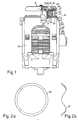
- Fig. 1 shows, schematically, a motor 10 with a built-on brake, generally designated by 11.
- the motor has a rotatable rotor shaft 12, on one end of which a brake disc 13 is secured.
- the motor can be of any suitable design and in the example a series motor has been chosen. The motor type is assumed to be known and will not be described in detail.
- the brake disc is provided with holes 14 for cooling purposes and, in addition, the brake disc has an inner peripheral surface 15 of a conical shape.
- the inner peripheral surface 15 on the brake disc cooperates with a braking surface 16 disposed on a cup-shaped part 17 which together with a bottom part 18 forms a housing 19.
- the housing encloses a magnet coil 20 wound on a core 21.
- the bottom part has a central, raised part 22 serving as a guide for the magnet coil on the bottom part.
- the cup-shaped part 17 has a peripheral edge 23 which extends horizontally at a distance from a likewise horizontal edge 24 on the bottom part 18. In the space between the two horizontal edges an annular spring or a spring washer 25 is inserted which forces the cup-shaped part in the direction away from the bottom part and towards the brake disc so that the cup-shaped part engages with the inner peripheral surface on the brake disc.
- the cup-shaped part 17 is made of magnetic steel while the brake disc is made from a material which is elastic to cause the desired self-locking effect.
- a thermoset plastics material has been chosen. It has appeared that, in addition to the fact that said desired effect is achieved, the material is resistant to wear and can be expected to have a life coinciding with the life of the motor.
- the inner peripheral edge 15 on the brake disc has a conical shape and the edge cooperates with a surface which is rounded and which connects the upper part of the cup-shaped part with the vertical annular side part of same.
- the spring washer 25 has a form so as to look like being wave-shaped when seen in the direction of the periphery. This is particularly apparent from Fig. 2b, showing the spring i a side view. In Fig. 2a the spring is shown in a top view. As the spring acts along the periphery of the cup-shaped part 17, mainly straight under the two cooperating brake surfaces, the brake force caused by the spring will be evenly distributed along the periphery so as to result in the best possible brake effect to be achieved. This should be compared to prior art embodiments wherein the brake force is produced by means of a number of coiled springs disposed along the periphery or even in the center, far away from the braking surfaces.
- Another advantage with the embodiment including the spring washer is that the magnetic coupling between the cup-shaped part 17 and the bottom part 18 becomes better than in embodiments with distributed coiled springs, whereby, when the motor is started, the cup-shaped part will very rapidly be moved away from its engagement with the brake disc.
Landscapes
- Engineering & Computer Science (AREA)
- General Engineering & Computer Science (AREA)
- Physics & Mathematics (AREA)
- Electromagnetism (AREA)
- Mechanical Engineering (AREA)
- Power Engineering (AREA)
- Braking Arrangements (AREA)
- Connection Of Motors, Electrical Generators, Mechanical Devices, And The Like (AREA)
Claims (4)
- Moteur électrique muni d'un frein actionnable par effet électromagnétique, ledit moteur (10) comprenant un arbre rotatif (12) sur lequel est calé un disque de freinage (13) qui coopère avec une surface de freinage (16), associée au moteur et ménagée sur une partie (17) en forme de cuvette, matérialisant l'une des moitiés d'un boîtier (19) dont l'autre moitié est constituée d'une partie inférieure (18), avec laquelle la partie en forme de cuvette emprisonne une bobine magnétique (20), ladite partie (17) en forme de cuvette étant mobile en direction de l'arbre du moteur, sous l'action d'un moyen élastique (25), de manière à amener la surface de freinage (16) au contact du disque de freinage (13), ladite partie (17) en forme de cuvette étant par ailleurs influencée, dans la direction opposée, par la force magnétique engendrée par la bobine magnétique au cours du fonctionnement du moteur, caractérisé par le fait que la surface de freinage (16) se présente comme un bord arrondi reliant respectivement, l'une à l'autre, les surfaces supérieure et latérale de ladite partie (17) en forme de cuvette, le disque de freinage (13) comportant une région marginale tronconique (15) qui coopère avec la surface de freinage (16) et étant constitué, en outre, d'un matériau doué d'élasticité dans une certaine mesure, afin d'exercer un effet d'autoverrouillage souhaité.
- Moteur selon la revendication 1, caractérisé par le fait que le disque de freinage (13) est constitué d'une matière plastique thermodurcissable.
- Moteur selon la revendication 1, caractérisé par le fait que la partie inférieure (18) du boîtier (19), renfermant la bobine magnétique (20), présente une région marginale (24) qui est orientée perpendiculairement à l'arbre (12) du moteur, ladite région marginale (24) étant directement située en vis-à-vis d'une région marginale correspondante (23), disposée sur la partie (17) en forme de cuvette dudit boîtier, le moyen élastique (25) consistant en une rondelle élastique annulaire, interposée entre les deux régions marginales.
- Moteur selon la revendication 3, caractérisé par le fait que la rondelle élastique (25) est de configuration ondulée le long de sa périphérie.
Applications Claiming Priority (2)
| Application Number | Priority Date | Filing Date | Title |
|---|---|---|---|
| SE9102066A SE468732B (sv) | 1991-07-02 | 1991-07-02 | Elektrisk motor foersedd med en elektromagnetiskt paaverkbar broms |
| SE9102066 | 1991-07-02 |
Publications (3)
| Publication Number | Publication Date |
|---|---|
| EP0521840A2 EP0521840A2 (fr) | 1993-01-07 |
| EP0521840A3 EP0521840A3 (en) | 1993-02-24 |
| EP0521840B1 true EP0521840B1 (fr) | 1995-08-09 |
Family
ID=20383236
Family Applications (1)
| Application Number | Title | Priority Date | Filing Date |
|---|---|---|---|
| EP19920850156 Expired - Lifetime EP0521840B1 (fr) | 1991-07-02 | 1992-06-24 | Moteur électrique avec un frein à fonctionnement par moyens électromagnétiques |
Country Status (3)
| Country | Link |
|---|---|
| EP (1) | EP0521840B1 (fr) |
| DE (1) | DE69203987T2 (fr) |
| SE (1) | SE468732B (fr) |
Families Citing this family (7)
| Publication number | Priority date | Publication date | Assignee | Title |
|---|---|---|---|---|
| GB2268987A (en) * | 1992-07-21 | 1994-01-26 | Warner Electric Limited | Electromagnetic braking systems |
| DE19857950A1 (de) * | 1998-12-16 | 2000-06-21 | Zahnradfabrik Friedrichshafen | Elektromotor mit einer integrierten, drehspielfreien, elektromagnetisch betätigten Bremse |
| EP1939483B1 (fr) * | 2006-12-27 | 2014-07-30 | PINTSCH BAMAG Antriebs- und Verkehrstechnik GmbH | Support de bobine pour l'électroaimant d'un frein électromagnétique, électroaimant, frein électromagnétique, procédé de fabrication d'un électroaimant, treuil à câble |
| US8263205B2 (en) | 2009-09-17 | 2012-09-11 | Hexcel Corporation | Method of molding complex composite parts using pre-plied multi-directional continuous fiber laminate |
| US9373987B2 (en) | 2013-09-11 | 2016-06-21 | Honda Motor Co., Ltd. | Integrated flywheels, systems and methods for electric generation and braking of a general purpose engine |
| CN107157240B (zh) * | 2017-03-28 | 2018-10-26 | 覃淑兰 | 一种便携式智能保温杯 |
| AT524801B1 (de) | 2021-02-23 | 2022-11-15 | Trumpf Maschinen Austria Gmbh & Co Kg | Elektromechanischer Spindelantrieb |
Family Cites Families (3)
| Publication number | Priority date | Publication date | Assignee | Title |
|---|---|---|---|---|
| FR2345843A1 (fr) * | 1976-03-22 | 1977-10-21 | Unelec | Moteur frein a deblocage manuel a action fugitive |
| DE7908186U1 (de) * | 1979-03-23 | 1979-08-23 | Binder Magnete Gmbh, 7730 Villingen | Elektromagnetisch gelueftete federdruckbremse |
| US4838391A (en) * | 1988-09-06 | 1989-06-13 | Xerox Corporation | Braking device |
-
1991
- 1991-07-02 SE SE9102066A patent/SE468732B/sv not_active IP Right Cessation
-
1992
- 1992-06-24 EP EP19920850156 patent/EP0521840B1/fr not_active Expired - Lifetime
- 1992-06-24 DE DE1992603987 patent/DE69203987T2/de not_active Expired - Fee Related
Also Published As
| Publication number | Publication date |
|---|---|
| SE468732B (sv) | 1993-03-08 |
| SE9102066L (sv) | 1993-01-03 |
| SE9102066D0 (sv) | 1991-07-02 |
| DE69203987T2 (de) | 1995-11-23 |
| DE69203987D1 (de) | 1995-09-14 |
| EP0521840A3 (en) | 1993-02-24 |
| EP0521840A2 (fr) | 1993-01-07 |
Similar Documents
| Publication | Publication Date | Title |
|---|---|---|
| US4381048A (en) | Electric motor with automatically acting brake | |
| DE69837161T2 (de) | Elektromotor mit innerer Bremse | |
| EP0537022B1 (fr) | Embrayage électromagnétique avec frein à aimant permanent | |
| EP0521840A2 (fr) | Moteur électrique avec un frein à fonctionnement par moyens électromagnétiques | |
| EP0367987B1 (fr) | Circuit de freinage pour un moteur-série | |
| EP1149458B1 (fr) | Moteur electrique pourvu d'un frein electromagnetique | |
| US6462449B1 (en) | Rotating electric machine with improved double excitation | |
| WO2017009123A1 (fr) | Machine électrique | |
| US3570226A (en) | Electrically driven lawnmower | |
| US5070266A (en) | Electromechanical device for stopping a shaft in at least one position | |
| EP0693633A2 (fr) | Frein à aimant permanent avec contrÔle électromagnétique | |
| AU616029B2 (en) | Electromagnetic clutch | |
| CA2072441C (fr) | Tondeuse a gazon | |
| US4661732A (en) | Safety device for a centrifugal actuator assembly | |
| WO1994021027A1 (fr) | Moteur serie, en particulier moteur universel, avec un systeme de freinage | |
| US4760898A (en) | Armature assembly | |
| US3760909A (en) | Electromagnet for brakes and clutches | |
| US2959695A (en) | Magnetic motor pole piece radial brake | |
| EP0422465A1 (fr) | Embrayage électromagnétique | |
| DE4007366A1 (de) | Elektromagnetische bremsvorrichtung | |
| JP3543009B2 (ja) | 電気ブレーキ付き直巻モータ | |
| US3315105A (en) | Speed control means for d.c. motors and method for making the same | |
| DE69309288T2 (de) | Elektrischer gebläsemotor | |
| CN215409863U (zh) | 制动器和电机 | |
| DE4106897A1 (de) | Elektromotor mit selbsttaetig wirkender bremse |
Legal Events
| Date | Code | Title | Description |
|---|---|---|---|
| PUAI | Public reference made under article 153(3) epc to a published international application that has entered the european phase |
Free format text: ORIGINAL CODE: 0009012 |
|
| AK | Designated contracting states |
Kind code of ref document: A2 Designated state(s): DE FR GB IT |
|
| PUAL | Search report despatched |
Free format text: ORIGINAL CODE: 0009013 |
|
| AK | Designated contracting states |
Kind code of ref document: A3 Designated state(s): DE FR GB IT |
|
| 17P | Request for examination filed |
Effective date: 19930320 |
|
| 17Q | First examination report despatched |
Effective date: 19941124 |
|
| GRAA | (expected) grant |
Free format text: ORIGINAL CODE: 0009210 |
|
| AK | Designated contracting states |
Kind code of ref document: B1 Designated state(s): DE FR GB IT |
|
| REF | Corresponds to: |
Ref document number: 69203987 Country of ref document: DE Date of ref document: 19950914 |
|
| ITF | It: translation for a ep patent filed | ||
| ET | Fr: translation filed | ||
| PLBE | No opposition filed within time limit |
Free format text: ORIGINAL CODE: 0009261 |
|
| 26N | No opposition filed | ||
| REG | Reference to a national code |
Ref country code: GB Ref legal event code: IF02 |
|
| PGFP | Annual fee paid to national office [announced via postgrant information from national office to epo] |
Ref country code: FR Payment date: 20050608 Year of fee payment: 14 |
|
| PGFP | Annual fee paid to national office [announced via postgrant information from national office to epo] |
Ref country code: DE Payment date: 20050616 Year of fee payment: 14 |
|
| PGFP | Annual fee paid to national office [announced via postgrant information from national office to epo] |
Ref country code: GB Payment date: 20050622 Year of fee payment: 14 |
|
| PG25 | Lapsed in a contracting state [announced via postgrant information from national office to epo] |
Ref country code: GB Free format text: LAPSE BECAUSE OF NON-PAYMENT OF DUE FEES Effective date: 20060624 |
|
| PGFP | Annual fee paid to national office [announced via postgrant information from national office to epo] |
Ref country code: IT Payment date: 20060630 Year of fee payment: 15 |
|
| PG25 | Lapsed in a contracting state [announced via postgrant information from national office to epo] |
Ref country code: DE Free format text: LAPSE BECAUSE OF NON-PAYMENT OF DUE FEES Effective date: 20070103 |
|
| GBPC | Gb: european patent ceased through non-payment of renewal fee |
Effective date: 20060624 |
|
| REG | Reference to a national code |
Ref country code: FR Ref legal event code: ST Effective date: 20070228 |
|
| PG25 | Lapsed in a contracting state [announced via postgrant information from national office to epo] |
Ref country code: FR Free format text: LAPSE BECAUSE OF NON-PAYMENT OF DUE FEES Effective date: 20060630 |
|
| PG25 | Lapsed in a contracting state [announced via postgrant information from national office to epo] |
Ref country code: IT Free format text: LAPSE BECAUSE OF NON-PAYMENT OF DUE FEES Effective date: 20070624 |