EP0521902B1 - Zum verschleiss ausgesetzte wand und mittel zu ihrer herstellung - Google Patents
Zum verschleiss ausgesetzte wand und mittel zu ihrer herstellung Download PDFInfo
- Publication number
- EP0521902B1 EP0521902B1 EP91905858A EP91905858A EP0521902B1 EP 0521902 B1 EP0521902 B1 EP 0521902B1 EP 91905858 A EP91905858 A EP 91905858A EP 91905858 A EP91905858 A EP 91905858A EP 0521902 B1 EP0521902 B1 EP 0521902B1
- Authority
- EP
- European Patent Office
- Prior art keywords
- portions
- wear
- arch
- base portions
- wall
- Prior art date
- Legal status (The legal status is an assumption and is not a legal conclusion. Google has not performed a legal analysis and makes no representation as to the accuracy of the status listed.)
- Expired - Lifetime
Links
Images


Classifications
-
- B—PERFORMING OPERATIONS; TRANSPORTING
- B02—CRUSHING, PULVERISING, OR DISINTEGRATING; PREPARATORY TREATMENT OF GRAIN FOR MILLING
- B02C—CRUSHING, PULVERISING, OR DISINTEGRATING IN GENERAL; MILLING GRAIN
- B02C17/00—Disintegrating by tumbling mills, i.e. mills having a container charged with the material to be disintegrated with or without special disintegrating members such as pebbles or balls
- B02C17/18—Details
- B02C17/22—Lining for containers
- B02C17/225—Lining for containers using rubber or elastomeric material
-
- B—PERFORMING OPERATIONS; TRANSPORTING
- B65—CONVEYING; PACKING; STORING; HANDLING THIN OR FILAMENTARY MATERIAL
- B65D—CONTAINERS FOR STORAGE OR TRANSPORT OF ARTICLES OR MATERIALS, e.g. BAGS, BARRELS, BOTTLES, BOXES, CANS, CARTONS, CRATES, DRUMS, JARS, TANKS, HOPPERS, FORWARDING CONTAINERS; ACCESSORIES, CLOSURES, OR FITTINGS THEREFOR; PACKAGING ELEMENTS; PACKAGES
- B65D90/00—Component parts, details or accessories for large containers
- B65D90/02—Wall construction
Definitions
- the present invention relates to a wall exposed to wear, which is made up of wear-resisting, impact-absorbing elements and a structure supporting said elements which comprise a wear-resisting, impact-absorbing layer of an elastomer or plastic material.
- the invention also relates to wall panels for making such a wall.
- Walls of this type can be used as wall panels in mill drums, skips, chutes, and as load-bearing surfaces, which when charged with material, often being large-size pieces of ore or stone, are subjected to heavy impacts and to wear or abrasion.
- these are often equipped with a wear-resistant layer of elastomer or plastic material directly engaging the supporting structure or suspended "hammockwise" to increase the flexibility of the material and to prevent breakage of the surface layer.
- US-A-3,350,832 This document describes a wall construction comprising wall panels and retainer elements.
- the main portion of the wall panels consists of rubber or plastic and is provided on its underside with protruding metal plates.
- the retainer elements are pressed against these metal plates so as to hold the wall panels clamped against the supporting structure.
- Another example of this known technology is disclosed in DE-A-1,482,420 (and the corresponding AT-C-254,048 and DK-B-122,370), where the wall panels have projecting flanges consisting of the same material as the rest of the wall panels, viz. rubber or plastic material.
- the wall panels are urged into tight engagement against the supporting structure by means of retainer elements fixed by screws.
- the wall panels are designed with weight-reducing recesses on their side facing the supporting structure.
- CH-A-580,984 discloses a lining in a ball mill.
- This lining also comprises wall panels of rubber or plastic and retainer elements, also serving as lifters.
- the lifters are partially recessed in the wall panels. To increase the clamping pressure in the boundary surface between the lifters and the wall panels, these have been designed, in one embodiment thereof, with recesses in their side facing the supporting structure.
- One object of the invention is to provide a wall which is made up of wear-resisting, impact-absorbing elements and which, despite being fixedly mounted on its supporting structure, has the required energy-absorbing ability and high impact resistance.
- the required energy-absorbing ability is achieved in that the wear-resisting, impact-absorbing elements are elongate and comprise spaced-apart base portions to permit mounting the elements on the supporting structure, and arch portions consisting of said wear-resistant elastomer or plastic material and extending freely between said base portions, and in that this elastomer or plastic material also extends throughout the base portions.
- the arch portions thereof will act as rubber springs and, while being resiliently deflected, absorb the energy of pieces of ore or stone hitting the wall.
- the major part of the kinetic energy of the pieces of ore or stone will have been absorbed by the elastic deformation of the arch portions before this deformation has progressed to such an extent that the arch portions are caused to engage the subjacent supporting structure.
- the invention also relates to means for making such a wall, which means comprises elements of the design described above.
- the wall exposed to wear is the bottom surface of a loading bin or platform for stone or ore.
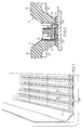
- the wall consists of a supporting structure 10 on which a number of elongate wear-resisting, impact-absorbing elements 11 are mounted side by side.
- the supporting structure is continuous, it may also consist of spaced-apart, parallel beams or a beam grating.
- a supporting structure 12 is provided with a retainer element 13 welded to the supporting structure. Stud bolts 14, welded to the retainer element 13, serve as fixing means for the base portions 15 of the elements 11.
- the base portions 15 have, integrated therein by vulcanisation or curing, a stiffening and reinforcing, elongate metal member 16. Holes 17 are formed in the base portions of the elements 11 in register with the stud bolts 14 to permit screwing nuts 18 onto the bolts 14. Between adjacent base portions 15 of each element 11 extends an arch portion 19 whose underside is spaced from the supporting structure 12.
- each element 11 has two base portions 15 and one arch portion 19 extending therebetween. In the embodiment of Figs 4-6, however, each element 11 has three base portions and two arch portions. Elements having one or two arch portions are preferred.
- the thickness of the elastomer or plastic material is substantially the same throughout the entire width of the element.
- the arch portion of elastomer or plastic material thus passes into a substantially equally thick, protective layer in the base portions.
- the wear-resisting, impact-absorbing elements are preferably provided with transverse stiffening ribs 20 which are integrally formed with the arch portion or portions and the free edge of which is located within the arch portion at a certain distance from a plane (top face of supporting structure 12) defined by the base portions 15.
- transverse stiffening ribs 20 which are integrally formed with the arch portion or portions and the free edge of which is located within the arch portion at a certain distance from a plane (top face of supporting structure 12) defined by the base portions 15.
- one stiffening rib is preferably disposed at each end of the element 11.
- the element 11 will be reinforced in this area, thereby avoiding or minimising any unnecessary detrimental deflection in said area as a result of an impact from pieces of stone or ore on the very joint between two successive elements.
- stiffening ribs 20 at different locations throughout the length of the elements 11.
- the ribs 20 should however have a small thickness in relation to the length of the elements, since they must not interfere to any considerable extent with the energy-absorbing deflection of the arch portion when subjected to impacts from pieces of ore or stone.
Landscapes
- Engineering & Computer Science (AREA)
- Mechanical Engineering (AREA)
- Food Science & Technology (AREA)
- Building Environments (AREA)
- Vibration Dampers (AREA)
- Laminated Bodies (AREA)
- Packaging Of Annular Or Rod-Shaped Articles, Wearing Apparel, Cassettes, Or The Like (AREA)
- Packaging Of Machine Parts And Wound Products (AREA)
- Chutes (AREA)
- Crushing And Grinding (AREA)
- Devices Affording Protection Of Roads Or Walls For Sound Insulation (AREA)
- Bridges Or Land Bridges (AREA)
- Absorbent Articles And Supports Therefor (AREA)
Claims (10)
- Wand, die aus verschleissfesten, prallaufnehmenden Elementen (11) und einer diese Elemente tragenden Struktur (12, 13) aufgebaut ist, wobei die Elemente eine verschleissfeste, prallaufnehmende Schicht aus einem verschleissfesten Elastomer oder Kunststoff bilden, wobei die verschleissfesten, prallaufnehmenden Elemente (11) in Längsrichtung langgestreckt sind und folgendes umfassen:
im Abstand voneinander angeordnete Fussteile (15) mit integrierten Gliedern (16) zur Anbringung der Elemente an der genannten Struktur, wobei die Fussteile sich in Querrichtung im Abstand voneinander befinden und eine sich in Längsrichtung erstreckende Länge haben, dadurch gekennzeichnet, dass
Bogenteile (19) aus dem genannten verschleissfesten Elastomer oder Kunststoff hergestellt sind und sich frei zwischen den Fussteilen erstrecken, wobei die Bogenteile als Gummifedern wirken, wobei die genannten Bogenteile sich auch in Längsrichtung über die Länge der genannten Fussteile erstrecken und
jedes Element (11) zumindest zwei Fussteile (15) und einen Bogenteil (19) zwischen jedem Fussteilpaar (15) hat, und
das Elastomer oder der Kunststoff sich auch von den Bogenteilen (19) erstreckt und direkt in eine Schutzschicht über die integrierten Glieder (16) übergeht und somit die Fussteile (15) bildet. - Wand nach Anspruch 1, dadurch gekennzeichnet, dass jedes Element (11) eine oder mehrere querverlaufende Versteifungsrippen (20) aufweist, die in einem Stück mit dem Bogenteil oder den Bogenteilen (19) ausgebildet sind und deren freie Kante sich innerhalb des Bogenteils in gewissem Abstand von einer durch die Fussteile (15) gebildeten Ebene befindet.
- Wand nach Anspruch 1 oder 2, dadurch gekennzeichnet, dass die Dicke des Bogenteils (19) zumindest 10 cm beträgt.
- Wand nach Anspruch 1, 2 oder 3, dadurch gekennzeichnet, dass die Dicke des Bogenteils (19) höchstens 50% der Gesamtdicke des Elements beträgt, vorzugsweise etwa 30-50% der Gesamtdicke des Elements.
- Wand nach einem der Ansprüche 1-4, dadurch gekennzeichnet, dass jeder Fussteil (15) ein aussteifendes oder verstärkendes Metallglied (16) aufweist, das im Elastomer oder Kunststoff eingebettet oder einvulkanisiert ist.
- Wandelement zur Herstellung einer Wand nach Anspruch 1, umfassend ein verschleissfestes, prallaufnehmendes Element (11) mit einer verschleissfesten, prallaufnehmenden Schicht aus einem verschleissfesten Elastomer oder Kunststoff, wobei das verschleissfeste, prallaufnehmende Element (11) in Längsrichtung langgestreckt ist und folgendes umfasst:
im Abstand voneinander angeordnete Fussteile (15) mit integrierten Gliedern (16) zur Anbringung der Elemente an einer Struktur, wobei die Fussteile in Querrichtung im Abstand voneinander angeordnet sind und eine sich in Längsrichtung erstreckende Länge haben, dadurch gekennzeichnet, dass
Bogenteile (19) aus dem genannten verschleissfesten Elastomer oder Kunststoff hergestellt sind und sich frei zwischen den Fussteilen erstrecken, wobei die Bogenteile als Gummifedern wirken, wobei die Bogenteile sich in Längsrichtung über die Länge der Fussteile erstrecken, und
das Element (11) zumindest zwei Fussteile (15) und einen Bogenteil (19) zwischen jedem Fussteilpaar (15) aufweist, und
das Elastomer oder der Kunststoff sich auch von den Bogenteilen (19) erstreckt und direkt in eine Schutzschicht über die integrierten Glieder (16) übergeht und somit die Fussteile (15) bildet. - Wandelement nach Anspruch 6, dadurch gekennzeichnet, dass das Element (11) eine oder mehrere querverlaufende Versteifungsrippen (20) aufweist, die in einem Stück mit dem Bogenteil oder den Bogenteilen (19) ausgebildet sind und deren freie Kante sich innerhalb des Bogenteils in gewissem Abstand von einer durch die Fussteile (15) abgegrenzten Ebene befindet.
- Wandelement nach Anspruch 6 oder 7, dadurch gekennzeichnet, dass die Dicke des Bogenteils (19) zumindest 10 cm beträgt.
- Wandelement nach Anspruch 6, 7 oder 8, dadurch gekennzeichnet, dass die Dicke des Bogenteils (19) höchstens 50% der Gesamtdicke des Elements beträgt, vorzugsweise etwa 30-50% der Gesamtdicke des Elements.
- Wandelement nach einem der Ansprüche 6-9, dadurch gekennzeichnet, dass jeder Fussteil (15) ein aussteifendes oder verstärkendes Metallglied (16) aufweist, das im Elastomer oder Kunststoff eingebettet oder einvulkanisiert ist.
Applications Claiming Priority (3)
| Application Number | Priority Date | Filing Date | Title |
|---|---|---|---|
| SE9000905A SE467533B (sv) | 1990-03-13 | 1990-03-13 | Foer noetning utsatt vaegg samt medel foer dess framstaellning |
| SE9000905 | 1990-03-13 | ||
| PCT/SE1991/000188 WO1991013737A1 (en) | 1990-03-13 | 1991-03-13 | Wall exposed to wear and means for making it |
Publications (2)
| Publication Number | Publication Date |
|---|---|
| EP0521902A1 EP0521902A1 (de) | 1993-01-13 |
| EP0521902B1 true EP0521902B1 (de) | 1995-03-01 |
Family
ID=20378856
Family Applications (1)
| Application Number | Title | Priority Date | Filing Date |
|---|---|---|---|
| EP91905858A Expired - Lifetime EP0521902B1 (de) | 1990-03-13 | 1991-03-13 | Zum verschleiss ausgesetzte wand und mittel zu ihrer herstellung |
Country Status (10)
| Country | Link |
|---|---|
| US (1) | US5185980A (de) |
| EP (1) | EP0521902B1 (de) |
| JP (1) | JPH05504911A (de) |
| CA (1) | CA2075503C (de) |
| DE (1) | DE69107839T2 (de) |
| ES (1) | ES2069283T3 (de) |
| FI (1) | FI98275C (de) |
| SE (1) | SE467533B (de) |
| WO (1) | WO1991013737A1 (de) |
| ZA (1) | ZA911837B (de) |
Families Citing this family (25)
| Publication number | Priority date | Publication date | Assignee | Title |
|---|---|---|---|---|
| US5253918A (en) * | 1992-12-01 | 1993-10-19 | Futurex Industries, Inc. | Truck bed liner with integral rail and tie-down fasteners |
| CA2149292C (en) * | 1994-05-12 | 1999-10-26 | Penda Acquisition, Inc. | Bedliner with snap-in load restraining member |
| US5803524A (en) * | 1996-01-05 | 1998-09-08 | Durakon Industries, Inc. | Sidewall protection panel with expansion accommodating members |
| US5906384A (en) * | 1996-10-23 | 1999-05-25 | F/G Products, Inc. | Cart system for moving product |
| AU725679B2 (en) * | 1996-11-25 | 2000-10-19 | Caterpillar Inc. | Liner for a work machine body |
| US5803531A (en) * | 1997-05-21 | 1998-09-08 | Nielsen; Jack T. | Liner system for a hauling compartment |
| US6007132A (en) * | 1998-01-13 | 1999-12-28 | Caterpillar Inc. | Liner for a work machine body and method for manufacturing the same |
| US6431629B1 (en) | 1998-09-01 | 2002-08-13 | Penda Corporation | Bedliner with anti-slip under layer |
| US6000741A (en) * | 1998-11-17 | 1999-12-14 | Caterpillar Inc. | Liner for a work machine body |
| US6194080B1 (en) | 1998-12-16 | 2001-02-27 | Caterpillar Inc. | Replaceable wear member |
| ES2155766B1 (es) * | 1999-01-26 | 2001-12-01 | Tecnomixer S L | Perfeccionamientos en las mezcladoras de sistema vertical para alimentos con melazas. |
| US6634505B1 (en) * | 1999-04-26 | 2003-10-21 | Durex Products, Inc. | Sieve bed for a sifting machine |
| US6174014B1 (en) | 1999-06-17 | 2001-01-16 | Caterpillar Inc. | Liner for a work machine body and method for manufacturing the same |
| US20030062372A1 (en) * | 2001-10-02 | 2003-04-03 | Metso Minerals (Trelleborg) Ab | Wear-resistant lining element and wear lining made thereof |
| US7059647B1 (en) * | 2002-12-31 | 2006-06-13 | Durakon Acquisition Corp. | Vehicle bed liner |
| US20050142333A1 (en) * | 2003-12-30 | 2005-06-30 | Montagna John C. | Method of manufacturing composite vehicle panels |
| US7163253B2 (en) * | 2003-12-30 | 2007-01-16 | Durakon Industries, Inc. | Method of manufacturing composite vehicle panels |
| SE528692C2 (sv) * | 2005-04-01 | 2007-01-23 | Sandvik Intellectual Property | En slitbeständig och bullerreducerande anordning |
| SE532593C2 (sv) * | 2006-05-05 | 2010-03-02 | Atlas Copco Rock Drills Ab | Anordning vid detalj till ett gruv- eller entreprenadfordon, omfattande en slitskyddsstruktur |
| EP2607161B1 (de) * | 2011-12-23 | 2019-12-25 | Metso Sweden AB | Verschleissbeständiges auskleidungselement zum kantenschutz und herstellungsverfahren dafür |
| US10076173B1 (en) * | 2014-11-28 | 2018-09-18 | Alexandre Rachid Kaidi | Embedded member nail clipper |
| EP3418589A1 (de) * | 2017-06-22 | 2018-12-26 | Metso Sweden Ab | Verfahren und befestigungsvorrichtung zur befestigung eines verkleidungselementes |
| CL2018002389A1 (es) * | 2018-08-21 | 2019-02-08 | Compania Electro Metalurgica S A | Levantadores para uso en equipos de conminución en faenas industriales y mineras |
| US12239201B1 (en) | 2023-10-11 | 2025-03-04 | edjy LLC | Single blade nail cutter |
| US12016444B1 (en) | 2023-10-11 | 2024-06-25 | edjy LLC | Single blade nail cutter |
Family Cites Families (17)
| Publication number | Priority date | Publication date | Assignee | Title |
|---|---|---|---|---|
| US1591938A (en) * | 1922-11-18 | 1926-07-06 | Allis Chalmers Mfg Co | Liner fastening |
| US2791463A (en) * | 1953-11-30 | 1957-05-07 | Fruehauf Trailer Co | Plastic liners and plastic ceiling liner for trailers |
| US3199261A (en) * | 1961-06-14 | 1965-08-10 | American Seal Kap Corp | Wall-like structure |
| BE629392A (de) * | 1962-03-08 | |||
| DE1482420B2 (de) * | 1963-06-18 | 1973-01-11 | Skelleftea Gummifabriks AB., Ersmark (Schweden) | Verschleissfutter aus gummi |
| DE1249058C2 (de) * | 1964-11-05 | 1973-03-22 | Verkleidung fuer waende | |
| SE372428B (de) * | 1973-05-18 | 1974-12-23 | Trelleborgs Gummifabriks Ab | |
| DE2354844C2 (de) * | 1973-11-02 | 1982-10-14 | Evt Energie- Und Verfahrenstechnik Gmbh, 7000 Stuttgart | Mahlschüssel-Auskleidung |
| DE2400812A1 (de) * | 1974-01-09 | 1975-07-17 | Stahlgruber Gruber & Co Otto | Schutzauskleidung aus elastischem material fuer rohrmuehlen |
| US3953950A (en) * | 1974-10-31 | 1976-05-04 | The Johnson Rubber Company | Truck bed liner and dock bumper combination |
| US4047749A (en) * | 1976-06-23 | 1977-09-13 | Zefflamb Industries, Inc. | Cargo box liner for pick-up trucks |
| US4162098A (en) * | 1977-06-13 | 1979-07-24 | Richardson Sam M | Protective liner for pickup trucks |
| US4341412A (en) * | 1980-04-24 | 1982-07-27 | Michael Wayne | Truck bed liner |
| US4791765A (en) * | 1981-12-28 | 1988-12-20 | Ford Motor Company | Synthetic material structural body panel |
| US4653246A (en) * | 1984-01-05 | 1987-03-31 | Hepler Jacque P | Insulation board for attachment to walls |
| US4693507A (en) * | 1984-05-08 | 1987-09-15 | Penda Corporation | Truck cargo bed liner with anti-slip surface |
| US4974895A (en) * | 1989-12-26 | 1990-12-04 | D & G Products, Inc. | Reinforced truck bed liner |
-
1990
- 1990-03-13 SE SE9000905A patent/SE467533B/sv not_active IP Right Cessation
-
1991
- 1991-03-12 US US07/667,312 patent/US5185980A/en not_active Expired - Fee Related
- 1991-03-13 JP JP3505904A patent/JPH05504911A/ja active Pending
- 1991-03-13 CA CA002075503A patent/CA2075503C/en not_active Expired - Fee Related
- 1991-03-13 EP EP91905858A patent/EP0521902B1/de not_active Expired - Lifetime
- 1991-03-13 WO PCT/SE1991/000188 patent/WO1991013737A1/en not_active Ceased
- 1991-03-13 ZA ZA911837A patent/ZA911837B/xx unknown
- 1991-03-13 ES ES91905858T patent/ES2069283T3/es not_active Expired - Lifetime
- 1991-03-13 DE DE69107839T patent/DE69107839T2/de not_active Expired - Fee Related
-
1992
- 1992-09-08 FI FI924023A patent/FI98275C/fi active
Also Published As
| Publication number | Publication date |
|---|---|
| SE467533B (sv) | 1992-08-03 |
| EP0521902A1 (de) | 1993-01-13 |
| SE9000905L (sv) | 1991-09-14 |
| JPH05504911A (ja) | 1993-07-29 |
| FI924023A0 (fi) | 1992-09-08 |
| ES2069283T3 (es) | 1995-05-01 |
| FI924023L (fi) | 1992-09-08 |
| FI98275C (fi) | 1997-05-26 |
| CA2075503A1 (en) | 1991-09-14 |
| DE69107839D1 (de) | 1995-04-06 |
| WO1991013737A1 (en) | 1991-09-19 |
| FI98275B (fi) | 1997-02-14 |
| CA2075503C (en) | 1997-11-18 |
| SE9000905D0 (sv) | 1990-03-13 |
| DE69107839T2 (de) | 1995-11-02 |
| US5185980A (en) | 1993-02-16 |
| ZA911837B (en) | 1991-12-24 |
Similar Documents
| Publication | Publication Date | Title |
|---|---|---|
| US5185980A (en) | Wall exposed to wear and means for making it | |
| RU2401238C2 (ru) | Износостойкая облицовка | |
| CA1049587A (en) | Truck bed liner and dock bumper combination | |
| RU2627260C2 (ru) | Износостойкий футеровочный элемент для защиты краев и способ его изготовления | |
| GB2107288A (en) | Impact-resistant wear plate | |
| EP1909961B1 (de) | Befestigungskreuz und befestigungsverfahren | |
| US11097795B2 (en) | Wear pad for a crawler track of a tracked vehicle, crawler track and construction machine | |
| US20160039608A1 (en) | Ceramic Chute Liner | |
| AU644426B2 (en) | Wall exposed to wear and means for making it | |
| US3822428A (en) | Joint inserts for bridging expansion joints | |
| CA1285917C (en) | Resilient rail-mounting | |
| WO2007105039A2 (en) | Lining arrangement | |
| RU2188892C2 (ru) | Селепропускной лоток | |
| RU2009924C1 (ru) | Верхняя рама с ударопрочным настилом пола вагона-самосвала | |
| CA2866344A1 (en) | A wear element system | |
| RU236922U1 (ru) | Футеровочная плита | |
| US20250135496A1 (en) | Improvements in vibratory screens | |
| PL89722B1 (de) | ||
| GB2219576A (en) | Wear strips | |
| KR200432583Y1 (ko) | 복공판이 필요 없는 임시 가설교량 | |
| RU2060053C1 (ru) | Футеровка | |
| GB2122176A (en) | Impact-resistant wear plate | |
| WO2025224729A1 (en) | Wear-impact resistant liner | |
| CZ276089A3 (en) | railroad level-crossing performed from sectional elements | |
| KR20150145230A (ko) | 세라믹 슈트 라이너 |
Legal Events
| Date | Code | Title | Description |
|---|---|---|---|
| PUAI | Public reference made under article 153(3) epc to a published international application that has entered the european phase |
Free format text: ORIGINAL CODE: 0009012 |
|
| 17P | Request for examination filed |
Effective date: 19920828 |
|
| AK | Designated contracting states |
Kind code of ref document: A1 Designated state(s): DE ES FR GB IT NL SE |
|
| 17Q | First examination report despatched |
Effective date: 19930701 |
|
| GRAA | (expected) grant |
Free format text: ORIGINAL CODE: 0009210 |
|
| AK | Designated contracting states |
Kind code of ref document: B1 Designated state(s): DE ES FR GB IT NL SE |
|
| PG25 | Lapsed in a contracting state [announced via postgrant information from national office to epo] |
Ref country code: IT Free format text: LAPSE BECAUSE OF FAILURE TO SUBMIT A TRANSLATION OF THE DESCRIPTION OR TO PAY THE FEE WITHIN THE PRESCRIBED TIME-LIMIT;WARNING: LAPSES OF ITALIAN PATENTS WITH EFFECTIVE DATE BEFORE 2007 MAY HAVE OCCURRED AT ANY TIME BEFORE 2007. THE CORRECT EFFECTIVE DATE MAY BE DIFFERENT FROM THE ONE RECORDED. Effective date: 19950301 Ref country code: NL Free format text: LAPSE BECAUSE OF NON-PAYMENT OF DUE FEES Effective date: 19950301 |
|
| REF | Corresponds to: |
Ref document number: 69107839 Country of ref document: DE Date of ref document: 19950406 |
|
| REG | Reference to a national code |
Ref country code: ES Ref legal event code: FG2A Ref document number: 2069283 Country of ref document: ES Kind code of ref document: T3 |
|
| ET | Fr: translation filed | ||
| NLV1 | Nl: lapsed or annulled due to failure to fulfill the requirements of art. 29p and 29m of the patents act | ||
| PLBE | No opposition filed within time limit |
Free format text: ORIGINAL CODE: 0009261 |
|
| STAA | Information on the status of an ep patent application or granted ep patent |
Free format text: STATUS: NO OPPOSITION FILED WITHIN TIME LIMIT |
|
| 26N | No opposition filed | ||
| PGFP | Annual fee paid to national office [announced via postgrant information from national office to epo] |
Ref country code: GB Payment date: 19980217 Year of fee payment: 8 |
|
| PGFP | Annual fee paid to national office [announced via postgrant information from national office to epo] |
Ref country code: DE Payment date: 19980305 Year of fee payment: 8 |
|
| PGFP | Annual fee paid to national office [announced via postgrant information from national office to epo] |
Ref country code: ES Payment date: 19980311 Year of fee payment: 8 |
|
| PGFP | Annual fee paid to national office [announced via postgrant information from national office to epo] |
Ref country code: FR Payment date: 19980316 Year of fee payment: 8 |
|
| PGFP | Annual fee paid to national office [announced via postgrant information from national office to epo] |
Ref country code: SE Payment date: 19980317 Year of fee payment: 8 |
|
| PG25 | Lapsed in a contracting state [announced via postgrant information from national office to epo] |
Ref country code: GB Free format text: LAPSE BECAUSE OF NON-PAYMENT OF DUE FEES Effective date: 19990313 |
|
| PG25 | Lapsed in a contracting state [announced via postgrant information from national office to epo] |
Ref country code: SE Free format text: LAPSE BECAUSE OF NON-PAYMENT OF DUE FEES Effective date: 19990314 |
|
| PG25 | Lapsed in a contracting state [announced via postgrant information from national office to epo] |
Ref country code: ES Free format text: LAPSE BECAUSE OF EXPIRATION OF PROTECTION Effective date: 19990315 |
|
| EUG | Se: european patent has lapsed |
Ref document number: 91905858.6 |
|
| GBPC | Gb: european patent ceased through non-payment of renewal fee |
Effective date: 19990313 |
|
| PG25 | Lapsed in a contracting state [announced via postgrant information from national office to epo] |
Ref country code: FR Free format text: LAPSE BECAUSE OF NON-PAYMENT OF DUE FEES Effective date: 19991130 |
|
| EUG | Se: european patent has lapsed |
Ref document number: 91905858.6 |
|
| REG | Reference to a national code |
Ref country code: FR Ref legal event code: ST |
|
| PG25 | Lapsed in a contracting state [announced via postgrant information from national office to epo] |
Ref country code: DE Free format text: LAPSE BECAUSE OF NON-PAYMENT OF DUE FEES Effective date: 20000101 |
|
| REG | Reference to a national code |
Ref country code: ES Ref legal event code: FD2A Effective date: 20010601 |