EP0522145B1 - Verfahren zur beseitigung von medizinischen abfallmaterialien - Google Patents
Verfahren zur beseitigung von medizinischen abfallmaterialien Download PDFInfo
- Publication number
- EP0522145B1 EP0522145B1 EP92905830A EP92905830A EP0522145B1 EP 0522145 B1 EP0522145 B1 EP 0522145B1 EP 92905830 A EP92905830 A EP 92905830A EP 92905830 A EP92905830 A EP 92905830A EP 0522145 B1 EP0522145 B1 EP 0522145B1
- Authority
- EP
- European Patent Office
- Prior art keywords
- contents
- vessel
- pressure vessel
- sterilization
- medical waste
- Prior art date
- Legal status (The legal status is an assumption and is not a legal conclusion. Google has not performed a legal analysis and makes no representation as to the accuracy of the status listed.)
- Expired - Lifetime
Links
Images


Classifications
-
- A—HUMAN NECESSITIES
- A61—MEDICAL OR VETERINARY SCIENCE; HYGIENE
- A61L—METHODS OR APPARATUS FOR STERILISING MATERIALS OR OBJECTS IN GENERAL; DISINFECTION, STERILISATION OR DEODORISATION OF AIR; CHEMICAL ASPECTS OF BANDAGES, DRESSINGS, ABSORBENT PADS OR SURGICAL ARTICLES; MATERIALS FOR BANDAGES, DRESSINGS, ABSORBENT PADS OR SURGICAL ARTICLES
- A61L2/00—Disinfection or sterilisation of materials or objects, in general; Accessories therefor
- A61L2/24—Apparatus using programmed or automatic operation
-
- A—HUMAN NECESSITIES
- A61—MEDICAL OR VETERINARY SCIENCE; HYGIENE
- A61L—METHODS OR APPARATUS FOR STERILISING MATERIALS OR OBJECTS IN GENERAL; DISINFECTION, STERILISATION OR DEODORISATION OF AIR; CHEMICAL ASPECTS OF BANDAGES, DRESSINGS, ABSORBENT PADS OR SURGICAL ARTICLES; MATERIALS FOR BANDAGES, DRESSINGS, ABSORBENT PADS OR SURGICAL ARTICLES
- A61L11/00—Methods specially adapted for refuse
-
- B—PERFORMING OPERATIONS; TRANSPORTING
- B02—CRUSHING, PULVERISING, OR DISINTEGRATING; PREPARATORY TREATMENT OF GRAIN FOR MILLING
- B02C—CRUSHING, PULVERISING, OR DISINTEGRATING IN GENERAL; MILLING GRAIN
- B02C19/00—Other disintegrating devices or methods
- B02C19/0056—Other disintegrating devices or methods specially adapted for specific materials not otherwise provided for
- B02C19/0075—Other disintegrating devices or methods specially adapted for specific materials not otherwise provided for specially adapted for disintegrating medical waste
-
- B—PERFORMING OPERATIONS; TRANSPORTING
- B09—DISPOSAL OF SOLID WASTE; RECLAMATION OF CONTAMINATED SOIL
- B09B—DISPOSAL OF SOLID WASTE NOT OTHERWISE PROVIDED FOR
- B09B3/00—Destroying solid waste or transforming solid waste into something useful or harmless
- B09B3/30—Destroying solid waste or transforming solid waste into something useful or harmless involving mechanical treatment
- B09B3/35—Shredding, crushing or cutting
-
- B—PERFORMING OPERATIONS; TRANSPORTING
- B09—DISPOSAL OF SOLID WASTE; RECLAMATION OF CONTAMINATED SOIL
- B09B—DISPOSAL OF SOLID WASTE NOT OTHERWISE PROVIDED FOR
- B09B3/00—Destroying solid waste or transforming solid waste into something useful or harmless
- B09B3/70—Chemical treatment, e.g. pH adjustment or oxidation
-
- B—PERFORMING OPERATIONS; TRANSPORTING
- B09—DISPOSAL OF SOLID WASTE; RECLAMATION OF CONTAMINATED SOIL
- B09B—DISPOSAL OF SOLID WASTE NOT OTHERWISE PROVIDED FOR
- B09B2101/00—Type of solid waste
- B09B2101/65—Medical waste
Definitions
- a method less frequently employed is the autoclaving of infectious materials prior to conventional disposal to render the materials sterile and harmless so they can be disposed of with kitchen and household refuse.
- these autoclaves comprise a large pressure vessel into which the waste is loaded. Steam is used to elevate the temperature inside the sealed autoclave until sterilization is achieved. Heat transfer must be effected through the tightly wrapped packages and plastic bags containing the medical waste, a slow and uneven process. Air trapped inside prevents good heat transfer so that cold spots exist which interfere with perfect sterilization unless the holding time is extended several hours to assure that all microorganisms have been rendered completely sterile.
- Another difficulty is the inability to control internal pressure, so that many bags or packages explode during the process inside the vessel, making the unloading after a long cool down very messy despite the elimination of the infection hazards. While this material might now be disposed of along with other kitchen and household garbage, many dump site operators refuse acceptance of autoclaved medical waste unless repackaged, ground up or otherwise made unrecognizable as medical waste.
- the criteria necessary for landfill acceptability include commercial sterility, nonrecognizability of waste components such as bandages, syringes, etc., and freedom from environmental toxicity.
- the present invention provides a safe, practical, and less costly method for disposing of infectious personal care waste (bandages, dressings, cotton, linen, gowns, masks, gloves, human waste, food service remnants, including plastic cups and plates, beverage cans, small instruments, needles, tubing, small glass flasks, et cetera), as well as some pathological waste such as body tissues, fluids and small bones or bone fragments.
- infectious personal care waste bandages, dressings, cotton, linen, gowns, masks, gloves, human waste, food service remnants, including plastic cups and plates, beverage cans, small instruments, needles, tubing, small glass flasks, et cetera
- pathological waste such as body tissues, fluids and small bones or bone fragments.
- the equipment used can either be configured for large municipal type use employing continuous process techniques, or it can be smaller, batch type, stand-alone processors for individual sites such as hospitals.
- the proposed process and equipment utilizes one or more pressures vessels fitted with either hammer mill or rotary knife tools for disintegration, and means of heating either by injection of steam or by heat conduction through a vessel jacket. Externally the vessel is fitted with thermocouples, a condenser and associated piping, a vacuum pump, and a carbon filter. A powerful motor is used for direct drive of the disintegration members. Direct motor drives are also used for the agitator (scraper) at slow speed (20 to 120 RPM) and, in the case of the continuous process version, for the helical screw drives.
- a control console with a programmable logic controller or microprocessor controls the process steps automatically, and a recording device provides printouts of conditions to provide hard copy proof of all parameters. Additionally powered valves are used in the continuous process version for transfers between vessels.
- FIG. 1 is a flow diagram of the batch process and processor of the present invention.
- FIG. 2A is a cutaway schematic plan view of a suitable processor or process vessel for use in the present invention.
- FIG. 2B is a cross-section of the apparatus of FIG. 2A in a manner to show the possible location and positioning of disintegration members such as knives within the processor.
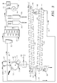
- FIG. 3 is a flow diagram of a continuous process and processor in accordance with the present invention that is suitable for a central or community medical waste disposal system.
- FIG. 1 The present invention, when conducted as a batch process, is illustrated in FIG. 1.
- FIGS. 2 and 2A should be read in conjunction with FIG 1 to illustrate in greater detail the process vessel or processor 10 of FIG. 1.
- the process vessel 10 is loaded with bags, packages or containers holding the medical waste.
- the vessel is closed hermetically by lid 11 and the process is initiated.
- Disintegration members 12 e.g., knife blades, grinders, or impact bars mounted on shaft 13, are initially driven by motor 14 at a rate of about 900 revolutions per minute, later at 1750, and up to 3500 RPM to disintegrate the contents of the vessel.
- Mixer-scraper 15 assures slow circulation of all materials through the path of the cutting or disintegration members 12; it is mounted on lid 11 and driven by motor 16.
- Heat is supplied by tangential steam injectors or similar steam injection devices 17. Alternatively, or supplementally, heat can be supplied by introduction of heating fluid into jacket 18 to heat up the contents to about 245 to 270 degrees Fahrenheit (about 118.33 to 132.22°C).
- Steam injection is greatly preferred because it gives far greater heat transfer in a shorter period of time and reduces the likelihood of "cold" spots, i.e. locations within the materials contained in the vessel which do not reach the necessary temperature to insure sterilization of the total vessel contents.
- a heating jacket can be used to provide supplemental heat and further insure the reaching of the necessary temperature in the interior of the processor 10. Only in those cases where a small load is utilized and a small processor can be utilized is the reliance on a heating jacket alone without steam injection recommended. In such cases, it is necessary to have a substantial preheat period and an extended processing period with substantial agitation in order to insure complete and thorough heating of the vessel contents.
- This temperature is maintained for approximately 30 to 60 minutes, depending on conditions, while size reduction continues. Since the type of waste material varies greatly, the duration of the heat application will have to be determined, e.g., by testing with inoculated material, to assure complete sterility in every case. The above temperature range was selected because plastic materials will not decompose, or melt at this temperature, while micro-organisms can safely be rendered sterile if the temperature is achieved in all parts of the contents and maintained for the predetermined period to achieve lethality. The combined activity of the agitator 15 and disintegration tool 12 will facilitate good mixing and heat transfer.
- the heat source is shut off and the interior of vessel 10 is vented to vacuum; a vacuum pump 19 is started to draw the atmosphere from the vessel 10 through an entrained solids separator 20 and through a heat exchanger-condenser 21. Because the temperature in the vessel is significantly above boiling point, the moisture, mostly water, flashes off as steam as soon as pressure is reduced, causing flash-cooling of the vessel contents.
- the vacuum pump 19 draws these water vapors through the heat exchanger-condenser 21 and exhausts entrained air through a carbon filter 22 to eliminate odors and/or any residual organic vapors.
- the condensate in most cases consisting of over 99% distilled water, is collected in a condensate receiver 23. Although the receiver can be directly connected to a sewer drain system, this system includes the capability of sampling before discharge is made. The biological and chemical oxygen demands of this discharge should be negligible and the active bacteria load nonexistent.
- the lid 11 and vessel 10 must be fitted with an automatic locking device, preventing the opening of the vessel before the sterilization process has run its course.
- the load consists of excessively dry materials, such as surgical uniforms or bed sheets, it may be necessary to add water to facilitate heat transfer.
- fibrous material such as bed sheets are involved, it may be desirable to add shear materials so that during the agitation, mixing and disintegration process there are materials present to aid the disintegration process.
- the shear materials will be organic particulate bulky materials such as sawdust which can mix with the materials contained in the processor to enhance the disintegration process.
- the disintegration members are typically breaker bars or knives such as heavy-duty, curved knives 12 mounted either pivoted like mill hammers, or fixed around a center shaft for direct drive by a motor 14. These are shown in FIG. 2B as mounted on pivots 27 which in turn are mounted on knife head 28. As shown in FIG. 2B, if the knife blade hits a solid object of a type which might cause the blade to wedge or break, the blade pivots backward, thereby preserving the knife blades and eliminating the jamming of the system. The knife head and shaft continue to rotate so that the cutting edges of the various knife blades continually hit the solid object 29 until it is suitably disintegrated.
- the system shown in FIG. 1 can be operated in a semi-continuous manner with certain relatively simple modifications.
- One or more additional process vessels of the types illustrated in FIGS. 2A and 2B can be combined in the system in parallel with the process vessel 10 shown in FIG 1.
- Appropriate valving preferably automatically controlled, permits the different process vessels to be operated independently of each other with each processing vessel at a different stage of processing than the other processing vessels.
- a second processor might be in the stage of venting to vacuum. If there is a third processor, it might be in the stage where the contents of the processor have been processed, fully sterilized and cooled, and are being discharged.
- a fourth processor might be in a loading stage. It is, of course, possible that two or more processors could operate at the same stage throughout the process and simultaneously vent to vacuum, et cetera. This, however, is not the most efficient use of peripheral equipment and might, for example, require an oversized vacuum pump to achieve the desired degree of vacuum in two or more vessels, whereas smaller equipment with lower power requirements could be used if only a single processing vessel were vented to vacuum at any one time.
- FIG. 3 illustrates a modification of the present invention which is conducted in a continuous manner for the handling of large volumes of medical waste.
- Those items of equipment corresponding to equipment used in the batch process are given to same numbers as in FIGS. 1, 2A and 2B.
- Two or more disintegrator vessels 40 (only one shown) of a suitable size such as 50 gallons (189.27 litres), are mounted in parallel above a first stage processor vessel 42.
- Each of the disintegrator vessels is of essentially the same general design, structure and function as the processor vessels illustrated in FIGS. 2A and 2B. The primary difference is in the method of operation.
- the processor vessels are used for both disintegration of the contents of the vessel and also for its sterilization.
- FIG. 3 illustrates a modification of the present invention which is conducted in a continuous manner for the handling of large volumes of medical waste.
- Those items of equipment corresponding to equipment used in the batch process are given to same numbers as in FIGS. 1, 2A and 2B.
- the primary function of vessel 40 is the disintegration of the contents.
- Steam is injected as in the batch process, but for somewhat different purposes. In the continuous process of FIG. 3, the steam injection serves as a pre-heater for the contents during disintegration. However, the contents of the vessel are discharged before sterilization is complete, unlike in the batch process. Steam injection and pressurization helps "push" the disintegrated contents of the vessel 40 out of the vessel at the appropriate stage and also the sterilizing of the empty vessel once the contents have been discharged, but prior to opening the vessel for the next load of unprocessed waste.
- the disintegrator vessels are separated from the processor vessel 42 by means of dual slide valves which allow selective connection or disconnection of the disintegrators 40 to the first stage processing vessel 42. All valve stems between gates and operators are steam traced similar to aseptic processing valves to prevent leakage of nonsterile matter or vapors.
- Each disintegrator 40 is fitted with hammer mill type or cutting tools 12 similar to those used in the stand-alone batch processor of FIG. 1. They are directly driven by motor 14.
- the vessel 40 has a lid 11 which is closed, locked and secured after filling, and a scraper/agitator 15 (FIG. 2A).
- a steam connection 17 allows direct injection of steam into the disintegrator 40 for heating, and assisting in material transfer.
- disintegrator vessel 40 Once a disintegrator vessel 40 has been filled, the cover 11 is locked, and size reduction and heat-up begin.
- the disintegrator vessel 40 at this stage is closed off from the first stage processor 42 by closed valve 44.
- the connecting slide valve 44 is opened, and the contents of the disintegrator are discharged and remnants are flushed out by steam into processor 42.
- the connecting valve 44 is left open long enough to allow the disintegrator vessel 40 to achieve sterility, whereupon the slide valve 44 is closed and the steam-air mixture in the disintegrator vessel 40 is vented through the vacuum system either into the second phase processing vessel 62 through valve 41 and line 45 or directly to discharge through valve 43 and line 46.
- the disintegrator 40 can now be re-opened and re-filled with a second charge.
- the second disintegrator vessel functions in exactly the same manner but its timing is offset so that one vessel is always available for loading, while the other one is processing material.
- the first phase processing vessel 42 receives pre-heated material at one end 54 and conveys it by means of a long helical screw 56 which also agitates the material as the material is delivered to the opposite end 58 while maintaining the temperature and pressure appropriate for sterilizing. Steam can be injected into the first phase processing vessel co-currently with the flow through injector 55 or counter-currently through steam injector 55'. In general, counter-current steam injection has been found preferential for steam penetration into the contents of the vessel and for sterilization. However, concurrent steam injection can be used provided the processor is of sufficient length and/or the residence time of the contents of the vessel is sufficient to give a time-temperature exposure of the contents to ensure thorough and complete sterilization. As in the batch processor, the first phase vessel 42 is maintained at a temperature in the 245 to 270 degrees Fahrenheit (118.33 to 132.22°C) range for sterilization without plastic melting or decomposition.
- First phase process vessel 42 is slightly inclined towards the discharge end so that the contents, pushed by the helical screw 56, are forced to travel "up hill” in their travel through the process vessel. Once again, this is provided to ensure thorough and complete mixing of the contents with sterilizing steam and to minimize the possibility of contents "slipping through” to the discharge end without adequate heat processing.
- a rotary vane-type transfer valve 60 e.g., a "transol" valve of the type manufactured by FMC Corporation
- the second phase vessel 62 is maintained under vacuum which results in a flash-off of most of the moisture while it causes the material to cool.
- Material is transferred through vessel 62 by a helical screw 63 to a multi-vane rotary transfer valve 64 which is used to discharge the material to the atmosphere without loosing the vacuum inside the vessel 62.
- the length of the vessels 42 and 62 and the conveying speed of the helical screws 56 and 63 are determined by the total volume of material which must be processed, and the conditions of temperature and time required for sterilization.
- the second phase processing vessel 62 is maintained under a vacuum in the range of 15 to 28 in. Hg. (0.508 to 0.948 bar) depending on the degree of dryness and the cost to achieve this.
- Piping and controls are essentially the same as those outlined for the batch processor with the added allowances for continuous operation. Also, as with the batch processor, parameters of all process conditions are continuously monitored and printed copies are produced for postprocess verification.
- the reaction vessel is subjected to a vacuum line which draws gases and then drains materials through a solid separator into a condenser from which liquid portions are condensed, and the uncondensed portion of the gas stream is vented to the air.
- the batch process of the present invention differs from the kitchen waste disposal system described in certain critical ways.
- the kitchen waste units do not have such a locking system. It is common practice to open the process vessel for the addition of additional kitchen waste for treatment, a practice that is absolutely forbidden when dealing with medical waste.
- the vessel In conjunction with the locked system, it is critical to have a programmable logic controller and/or microprocessor to monitor and control the locking procedure based on the time-temperature exposure of the contents.
- the vessel must have some type of a temperature indicator, such as a thermocouple, keyed into the microprocessor so that the microprocessor can monitor the length of time that the contents have been at or above the sterilization temperature.
- a temperature indicator such as a thermocouple
- the contents of the vessel be maintained at any specified sterilization temperature for a period of time sufficient to destroy the microorganisms, and for a time to insure adequate penetration of the heat into the inner portions of the waste materials to be treated.
- the use of injected steam, added water, high pressure, comminution, agitation, and mixing all serve to enhance the heat penetration and increase the effectiveness of the sterilization. It is, therefore, a function of the microprocessor to insure that all of the parameters are satisfied in order to insure that adequate and complete sterilization results.
- the temperature is too high, i.e. above about 270° Fahrenheit (132.22°C)
- many of the polymeric materials such as plastics that may be characteristically found in medical waste, will soften and/or become gummy and will interfere with the effective operation of the processing vessel, both as to adequacy of mixing and as to heat penetration.
- many of the plastics decompose at higher temperatures to produce gases, some of which may be toxic. Higher temperatures also favor the production of dioxin. Highly toxic residues and/or ash may result.
- the upper temperature limit is also critical.
- the microprocessor or computer it is also a function of the microprocessor or computer to ensure that the contents of the processing vessel have been satisfactorily reduced in particle size.
- the very hard particles should be reduced to a size of less than one-half (1/2) inch (12.7 mm), e.g., approximately three-eighths (3/8ths) inch (9.525 mm) or less, in order to ensure relatively rapid and complete mixing with heating medium and to ensure good heat penetration.
- the softer materials will be reduced generally to a pulp if the very hard materials are reduced to three-eighths (3/8ths) inch (9.525 mm) size.
- the microprocessor will primarily control the basis of heat treatment and sterilization; however, as previously indicated, in the embodiment shown in FIG. 3, the sterilization is controlled in the first phase process vessel 42, thus the microprocessor will control the disintegrator vessel 40 according to particle size and possibly preheat rather than on the basis of degree of sterilization of the waste content.
- the microprocessor In the embodiment of FIG. 3 with valves 44 open, there are approximately six to nine inches (152.4 to 228.6 mm) (diameter) so that the disintegrated materials can pass through readily.
- the vessel contents should be below 140 degrees Fahrenheit (60°C), and preferably below 120 degrees Fahrenheit (48.89°C) at the time of discharge.
- 60°C 140 degrees Fahrenheit
- 48.89°C 120 degrees Fahrenheit
- thermocouple or other temperature-indicating device which can be connected to provide information to the microprocessor so that the microprocessor can open and/or release any locks necessary to permit discharge of the vessel.
- the system will cool merely by standing without heat input. The step of drawing a vacuum on the processor following heating will provide substantial rapid cooling as a result of the evaporative cooling effect.
- microprocessor control the process. It is also essential that it have associated with it a printing recorder so that continuous records of the process and the completion of the time-temperature can be shown to the satisfaction not only of the operators of the system, but also to the appropriate governmental agencies which monitor waste systems of this type. Still another requirement of the medical waste processing system, that is not generally characteristic of that use for kitchen waste, is the inclusion of an appropriate filter 22 at the discharge end of vacuum pump 19 (FIG. 1). Because of the potential of contamination from medical wastes it is essential that this type of filtration device be in place whereas, it is not a matter of concern when dealing with normal kitchen wastes. An activated carbon filter will generally suffice with the process of the present invention.
- pH Another controllable factor which can be adjusted to enhance the sterilization process and provide a higher degree of safety while permitting shorter sterilization periods is pH.
- suitable acid such as acetic acid
- acetic acid to lower the pH, preferably to a value below 4.5, would, in most instances, constitute the preferred operation.
- acetic acid it may not, however, be readily possible to lower the pH in this manner.
- Many medical wastes contain high levels of buffers such as blood, proteins, and the like, which resist the lowering of pH by the addition of acid unless very large quantities of acid are used. In such cases, it may be necessary to forego pH lowering and utilize the longer heating cycles to ensure complete sterilization.
- an in-line titration system that is self-sterilizing (e.g. a closed loop system which can be steam-sparged during or after each run) that is capable of giving the appropriate pH/buffer information to permit a ready determination of the efficacy of acid addition.
- the primary purpose of the present invention is to ensure not only the safe disposal of waste, but also the safe handling of waste.
- a carbon filter (filter 22 in the figures)
- This filter preferably should be a three-stage unit consisting of a combination of a prefilter, a HEPA (high efficiency particle arrestor) filter, and an activated carbon filter.
- the present invention is capable of providing sterilization in which all of the pathogens and micro-organisms have been destroyed, as distinguished from simple disinfection in which the number of micro-organisms or pathogens is reduced to a low level such as that level at which exposure to a susceptible host should not result in an infectious disease.
- the process of the present invention provides a highly reliable, safe and economical method for treatment of potentially infectious medical waste.
- the product of the operation is a residue that can be accepted in regular landfill disposal sites since, after processing, the waste residue is significantly reduced in volume, i.e. by a factor of seven or better, is unrecognizable as medical in origin, is essentially free of "sharps", and poses no chemical or microbiological hazard to the waste sites or to the operators, even if extended hauling or storage is required.
- the process further renders all equipment areas which are exposed to infectious matter completely sterile since the machinery and equipment cannot be opened and accessed for loading, unloading or maintenance until after the completion of the sterilization process.
Landscapes
- Health & Medical Sciences (AREA)
- Engineering & Computer Science (AREA)
- General Health & Medical Sciences (AREA)
- Environmental & Geological Engineering (AREA)
- Veterinary Medicine (AREA)
- Public Health (AREA)
- Animal Behavior & Ethology (AREA)
- Life Sciences & Earth Sciences (AREA)
- Epidemiology (AREA)
- Toxicology (AREA)
- Chemical Kinetics & Catalysis (AREA)
- General Chemical & Material Sciences (AREA)
- Chemical & Material Sciences (AREA)
- Food Science & Technology (AREA)
- Processing Of Solid Wastes (AREA)
- Apparatus For Disinfection Or Sterilisation (AREA)
- Supply And Distribution Of Alternating Current (AREA)
- Management, Administration, Business Operations System, And Electronic Commerce (AREA)
Claims (4)
- Verfahren zur Beseitigung von medizinischem Abfallmaterial, umfassend die folgenden Schritte:A. Einleiten von zu behandelndem medizinischem Abfallmaterial in einen Druckkessel mit rotierbarem Aufschlußmittel;B. Verschließen des genannten Druckkessels mit einem Verschlußmittel gegen eine unkontrollierte Freisetzung des Inhalts;C. Verriegeln des genannten Verschlußmittels auf eine solche Weise, daß ein versehentliches Öffnen des genannten Druckkessels vor der Sterilisation des Inhalts verhindert wird;D. Aktivieren des genannten rotierbaren Aufschlußmittels zur Bewirkung einer erheblichen physikalischen Reduktion des Inhalts des genannten Druckkessels;E. Erhitzen des Inhalts des genannten Druckkessels auf eine Temperatur im Bereich zwischen etwa 245 und 270°F (118,33 bis 132,22°C) und Halten des Inhalts auf einer Temperatur in dem genannten Bereich für eine Zeit, die zur Zerstörung von in dem genannten medizinischen Abfallmaterial enthaltenen Mikroorganismen ausreicht;F. Beenden des Erhitzens des Inhalts des genannten Druckkessels;G. Ziehen eines Vakuums auf den genannten Druckkessel durch einen Abscheider für mitgeführte Feststoffe, einen Flüssigkeitskondensator und einen Kondensatempfänger mit Hilfe einer Vakuumpumpe und Leiten des Abstroms von der genannten Vakuumpumpe durch ein Filter eines Aktivkohletyps, undH. Ablassen des Inhalts des genannten Druckkessels;
wobei ferner vorgesehen ist, daß alle Schritte des genannten Verfahrens außer der ersten Beschickung des Druckkessels mit medizinischem Abfallmaterial sowie das Ablassen von medizinischem Abfallmaterial daraus mit automatischen Steuermitteln gesteuert werden, die mit Aufzeichnungsmitteln ausgestattet sind, um nachprüfbare Aufzeichnungen der Sterilisation des Inhalts des genannten Druckkessels bereitzustellen. - Verfahren nach Anspruch 1, wobei der Erhitzungsschritt E eine Dampfinjektion umfaßt und wobei ein Vakuum von wenigstens 25 Zoll Quecksilbersäule (0,846 bar) nach dem Verriegelungsschritt C und vor den Erhitzungsschritt E auf den Druckkessel gezogen wird.
- Verfahren zur kontinuierlichen Beseitigung von medizinischem Abfallmaterial, umfassend die folgenden Schritte:A. Einleiten von zu behandelndem medizinischem Abfallmaterial in einen Druckkessel mit rotierbaren Aufschlußmittel;B. Verschließen des genannten Druckkessels mit einem Verschlußmittel gegen eine unkontrollierte Freisetzung des Inhalts;C. Verriegeln des genannten Verschlußmittels auf eine solche Weise, daß ein versehentliches Öffnen des genannten Druckkessels vor der Sterilisation des Inhalts verhindert wird;D. Aktivieren des genannten rotierbaren Aufschlußmittels zur Bewirkung einer erheblichen physikalischen Reduktion des Inhalts des genannten Druckkessels;E. Injizieren von Dampf in den Inhalt des genannten Druckkessels wahrend der genannten physikalischen Reduktion;F. Beenden der genannten physikalischen Reduktion des Inhalts des genannten Druckkessels, wenn die Partikelgröße des Inhalts weniger als ein halbes (1/2) Zoll (12,7 cm) beträgt;G. Ablassen des Inhalts des genannten Druckkessels in einen unter Druck stehenden Sterilisationskessel;H. Pressen des Inhalts des genannten unter Druck stehenden Sterilisationskessels durch den genannten unter Druck stehenden Sterilisationskessel unter Rühren und Mischen bei gleichzeitigem Injizieren von Dampf in den genannten unter Druck stehenden Sterilisationskessel zwecks Vermischen mit dem und Sterilisierung des genannten Inhalt(s) des unter Druck stehenden Sterilisationskessels, um den Inhalt des genannten Druckkessels auf eine Temperatur im Bereich zwischen etwa 245 und 270°F (etwa 118,33 bis 132,22°C) zu erhitzen;I. Ablassen des Inhalts des genannten Sterilisationskessels in einen Vakuumkessel, wobei der Inhalt eine Temperatur in dem genannten Temperaturbereich für einen Zeitraum erreicht hat und dort gehalten wird, der ausreicht, um in dem genannten medizinischen Abfallmaterial enthaltene Mikroorganismen abzutöten;J. Pressen des behandelten, aus dem genannten Vakuumkessel abgelassenen medizinischen Abfallmaterials durch den genannten Vakuumkessel unter Rühren und Mischen, bis die genannten Materialen eine Temperatur unter 140°F (60°C) erreicht haben;K. Ablassen des gekühlten Inhalts aus dem genannten Vakuumkessel, der eine Temperatur unter 140°F (60°C) hat;
und ferner umfassend eine Verbindung zwischen dem genannten Vakuumkessel und einer Vakuumpumpe, so daß Raum oberhalb des Inhalts des genannten Vakuumkessels durch einen Abscheider für mitgeführte Feststoffe, einen Flüssigkeitskondensator und einen Kondensatempfänger evakuiert wird, und der Abstrom von der genannten Vakuumpumpe durch ein Filter eines Aktivkohletyps geleitet wird, und wobei ferner vorgesehen ist, daß alle Schritte des genannten Verfahrens außer der ersten Beschickung des Druckkessels mit medizinischem Abfallmaterial sowie das Ablassen von medizinischem Abfallmaterial daraus mit automatischen Steuermitteln gesteuert werden, die mit Aufzeichnungsmitteln ausgestattet sind, um nachprüfbare Aufzeichnungen der Sterilisation des Inhalts des genannten Druckkessels bereitzustellen. - Verfahren nach Anspruch 1, 2 oder 3, bei dem der pH-Wert von behandelten Abfallprodukten durch die Zugabe von Säure auf einen Wert unter etwa 4,5 reduziert wird.
Applications Claiming Priority (5)
| Application Number | Priority Date | Filing Date | Title |
|---|---|---|---|
| US64572491A | 1991-01-25 | 1991-01-25 | |
| US824560 | 1992-01-23 | ||
| US645724 | 1992-01-23 | ||
| US07/824,450 US5217688A (en) | 1991-01-25 | 1992-01-23 | Process for the disposal of medical waste |
| PCT/US1992/000614 WO1992012738A1 (en) | 1991-01-25 | 1992-01-24 | Process and device for the disposal of medical waste |
Publications (3)
| Publication Number | Publication Date |
|---|---|
| EP0522145A1 EP0522145A1 (de) | 1993-01-13 |
| EP0522145A4 EP0522145A4 (en) | 1993-06-16 |
| EP0522145B1 true EP0522145B1 (de) | 1998-04-29 |
Family
ID=27094761
Family Applications (1)
| Application Number | Title | Priority Date | Filing Date |
|---|---|---|---|
| EP92905830A Expired - Lifetime EP0522145B1 (de) | 1991-01-25 | 1992-01-24 | Verfahren zur beseitigung von medizinischen abfallmaterialien |
Country Status (7)
| Country | Link |
|---|---|
| US (1) | US5217688A (de) |
| EP (1) | EP0522145B1 (de) |
| JP (1) | JPH06102072B2 (de) |
| CA (1) | CA2079003C (de) |
| DE (1) | DE69225275T2 (de) |
| MX (1) | MX9300109A (de) |
| WO (1) | WO1992012738A1 (de) |
Families Citing this family (78)
| Publication number | Priority date | Publication date | Assignee | Title |
|---|---|---|---|---|
| US5600394A (en) * | 1984-05-12 | 1997-02-04 | Eastman Kodak Company | Smart film cartridge magazine |
| US5427737A (en) * | 1991-10-03 | 1995-06-27 | Anteus Group, Inc. | Process and system for biologically neutralizing waste material |
| US5582793A (en) * | 1991-10-03 | 1996-12-10 | Antaeus Group, Inc. | Process for treating waste material |
| US5362443A (en) * | 1991-12-27 | 1994-11-08 | Nippon Metal Industry Co., Ltd. | Method and apparatus for disposal of medical waste |
| US5424046A (en) * | 1992-02-28 | 1995-06-13 | Smith; Benjamin G. | Method and apparatus for steam sterilization |
| US5431878A (en) * | 1992-10-28 | 1995-07-11 | Atlanta International Waste, Inc. | Refuse sterilization system |
| FR2697754B1 (fr) * | 1992-11-10 | 1994-12-02 | Lagarde Ste Nouvelle Ets J | Procédé et machine pour le traitement de déchets médicaux. |
| US5340536A (en) * | 1992-12-18 | 1994-08-23 | 3-I Systems | Method and apparatus for neutralization of biohazardous waste |
| DE69410838T2 (de) * | 1993-01-29 | 1998-11-12 | Able Corp | Autoklav |
| CA2157775C (en) | 1993-03-08 | 2004-09-07 | Terry Randolph Galloway | Method and system for detoxifying solid waste |
| FR2704758B1 (fr) * | 1993-05-06 | 1995-07-28 | Lajtos Sa Ets | Procédé de traitement thermique de matière au moyen de vapeur notamment en vue de leur stérilisation et moyens pour la mise en Óoeuvre du procédé de traitement thermique précité. |
| US5424033A (en) * | 1993-05-07 | 1995-06-13 | Teb Holding S.A. | Process and autoclave system for size reducing and disinfecting contaminated hospital refuse |
| IT1260938B (it) * | 1993-07-21 | 1996-04-29 | Roberto Pellegrin | Procedimento e macchina per sterilizzare o disinfettare i rifiuti. |
| IL108311A (en) * | 1994-01-10 | 1999-09-22 | Moledet Kfar Bnei Brith | Method and equipment for disinfection of medical waste |
| FR2715851B1 (fr) * | 1994-02-08 | 1996-04-12 | Gerard Bollinger | Procédé et installation de stérilisation-broyage d'étage pour déchets hospitaliers. |
| US5475464A (en) * | 1994-05-12 | 1995-12-12 | Eastman Kodak Company | Smart film cartridge magazine |
| US5493352A (en) * | 1994-05-12 | 1996-02-20 | Eastman Kodak Company | Film cartridge magazine |
| US5666878A (en) * | 1994-08-26 | 1997-09-16 | Dover Corporation | Waste disposal system which includes a vessel with an outer cooling jacket |
| DE69421814D1 (de) * | 1994-10-21 | 1999-12-30 | Vomm Impianti & Processi Srl | Verfahren zur Beseitigung von pathogene Bestandteile enthaltendem Müll |
| US5759491A (en) * | 1995-07-21 | 1998-06-02 | Bunin; Kiva | Process and apparatus for the decontamination of infectious waste |
| JP3082185B2 (ja) * | 1995-12-27 | 2000-08-28 | 株式会社キーアンドクラフト | 表土等の清掃滅菌装置 |
| GB2310485B (en) * | 1996-02-24 | 1999-04-28 | Morgan Automation Ltd | Waste disposal unit |
| JPH10295552A (ja) * | 1997-04-25 | 1998-11-10 | Mk Seiko Co Ltd | 製パン機 |
| US6139793A (en) | 1997-09-05 | 2000-10-31 | Hydroclave Systems Corporation | Waste treatment control system |
| US6001305A (en) * | 1998-05-12 | 1999-12-14 | Steris Corporation | Sterilizer with elliptical pressure vessel |
| US6263785B1 (en) * | 1998-06-09 | 2001-07-24 | David R. Zittel | Blancher and method of operation |
| DE19833024C2 (de) * | 1998-07-23 | 2003-05-15 | Helmut Goeldner | Verfahren und Vorrichtung zur Desinfektion oder Sterilisation von infizierten Materialien |
| IL131510A0 (en) * | 1999-08-19 | 2001-01-28 | Pessach Seidel | Pasteurization of organic particulate material |
| JP2001149447A (ja) * | 1999-11-26 | 2001-06-05 | Cosmo Project Kk | 感染性廃棄物の滅菌方法 |
| JP2002102316A (ja) * | 2000-10-03 | 2002-04-09 | Chiyoda Manufacturing Co Ltd | 高圧蒸気滅菌装置 |
| US6494391B2 (en) * | 2001-02-05 | 2002-12-17 | M.C.M. Environmental Technologies Ltd. | Apparatus for treating waste, particularly medical waste, to facilitate its disposition |
| ES2294095T3 (es) * | 2001-07-03 | 2008-04-01 | W & H STERILIZATION S.R.L. | Disposicion para sistemas de autoclave. |
| NZ533075A (en) * | 2001-10-22 | 2004-08-27 | Univ Alabama | A method for preparing a homogenous cellulosic product from cellulosic waste materials |
| ITPD20020027A1 (it) * | 2002-02-05 | 2003-08-05 | Econos Srl | Dispositivo per la sterilizzazione di rifiuti ospedalieri. |
| MY138555A (en) * | 2003-06-02 | 2009-06-30 | Jgc Corp | High-pressure treatment apparatus and method for operating high-pressure treatment apparatus |
| US7967877B2 (en) * | 2003-11-13 | 2011-06-28 | Biomass Worldwide Group Limited | Biomass energy product and processing method |
| US20090004051A1 (en) * | 2004-04-12 | 2009-01-01 | Sanitec Industries, Inc. | Processing of Documents with Medical and Other Waste |
| US20050228694A1 (en) * | 2004-04-12 | 2005-10-13 | Sanitec Industries, Inc., A California Corporation | Processing of documents with medical and other waste |
| ITMI20041422A1 (it) * | 2004-07-15 | 2004-10-15 | Esambra S R L | Impianto di trattamento di rifiuti ospedalieri e simili |
| WO2006015423A1 (en) * | 2004-08-11 | 2006-02-16 | Clifford C Holloway | Method and apparatus for collection and treatment of encapsulated waste |
| US20060045797A1 (en) * | 2004-08-27 | 2006-03-02 | Don Frazier | System for treating bio-hazardous medical waste |
| GB0501864D0 (en) * | 2005-01-31 | 2005-03-09 | 3Dm Environmental Ltd | Treatment and recovery of waste |
| US20060219099A1 (en) * | 2005-04-05 | 2006-10-05 | Yun Pan | Automatic cooker |
| US7678112B2 (en) * | 2005-04-26 | 2010-03-16 | Warsaw Orthopedic, Inc. | Open dorsal adjusting connector |
| US7347391B2 (en) * | 2005-05-05 | 2008-03-25 | Estech, Llc | Waste processing apparatus and method |
| US8875881B2 (en) * | 2005-09-27 | 2014-11-04 | Covidien Ag | Method and apparatus for collecting sharps |
| US20070068833A1 (en) * | 2005-09-27 | 2007-03-29 | Smudde Anton M | Method and apparatus for collecting sharps |
| US8584850B2 (en) * | 2005-09-27 | 2013-11-19 | Covidien Ag | Apparatus for collecting sharps |
| US7789230B2 (en) * | 2005-09-27 | 2010-09-07 | Covidien Ag | Method and apparatus for collecting sharps |
| US7745208B2 (en) | 2006-02-15 | 2010-06-29 | Noll Anthony P | Angled reaction vessel |
| US8728802B2 (en) * | 2006-02-15 | 2014-05-20 | Biomass Worldwide Group Limited | Angled reaction vessel |
| US20080063580A1 (en) * | 2006-06-07 | 2008-03-13 | Von Lersner Wolf A | Safeguard for bio-indicators in medical waste autoclaves |
| US20080050274A1 (en) * | 2006-06-07 | 2008-02-28 | Brian Ozier | Process for treating medical waste |
| RU2339404C2 (ru) * | 2006-06-13 | 2008-11-27 | Открытое Акционерное Общество "НПК "Механобр-техника" | Способ и устройство для стерилизации инфицированных отходов |
| US7497392B2 (en) * | 2006-07-17 | 2009-03-03 | Alliance Technology Group, Inc. | Process and apparatus for transforming waste materials into fuel |
| US8025173B2 (en) | 2006-09-07 | 2011-09-27 | Allegiance Corporation | Collapsible canister liner for medical fluid collection |
| US8460256B2 (en) | 2009-07-15 | 2013-06-11 | Allegiance Corporation | Collapsible fluid collection and disposal system and related methods |
| US9889239B2 (en) | 2007-03-23 | 2018-02-13 | Allegiance Corporation | Fluid collection and disposal system and related methods |
| US8500706B2 (en) | 2007-03-23 | 2013-08-06 | Allegiance Corporation | Fluid collection and disposal system having interchangeable collection and other features and methods relating thereto |
| US7534405B1 (en) | 2008-05-14 | 2009-05-19 | Infection Management, Inc. | Waste processing for pathogen reduction |
| US8366996B2 (en) | 2010-09-01 | 2013-02-05 | Defraites Robert | Refuse disinfection system |
| WO2012054722A2 (en) * | 2010-10-22 | 2012-04-26 | Progressive Recovery, Inc. | Method and apparatus for sterilizing infectious material |
| US9199242B2 (en) | 2011-01-06 | 2015-12-01 | Trinova Medical Waste Solutions, Llc | Hazardous waste sanitation and removal device, methods of use and applications thereof |
| ITBA20110015A1 (it) * | 2011-04-07 | 2012-10-08 | Eco System S U R L | "autoclave per la sterilizzazione dei rifiuti ospedalieri e suo procedimento" |
| FI20115350A0 (fi) * | 2011-04-12 | 2011-04-12 | Steris Europe Inc | Laite kiintoaineen erottamiseksi biojätesuspensiosta |
| ITTO20111091A1 (it) * | 2011-11-28 | 2013-05-29 | Fater Spa | Apparecchiatura e procedimento per il riciclaggio di prodotti sanitari assorbenti |
| JP2013220131A (ja) * | 2012-04-13 | 2013-10-28 | Green:Kk | 滅菌処理装置、及び、滅菌処理方法 |
| ITCZ20120010A1 (it) * | 2012-08-02 | 2014-02-03 | Luigi Sauve | Dispositivo di dissipazione e triturazione della parte umida dei rifiuti urbani |
| US8721987B1 (en) | 2012-12-26 | 2014-05-13 | Robert DeFraites | Refuse disinfection system |
| US11458414B2 (en) * | 2013-10-13 | 2022-10-04 | Synergy Burcell Technologies, Llc | Methods and apparatus utilizing vacuum for breaking organic cell walls |
| DE102015109335A1 (de) * | 2015-06-11 | 2016-12-15 | Fritsch Gmbh | Messermühle |
| US10136632B2 (en) | 2016-05-12 | 2018-11-27 | Jiro Yamamoto | Modified field incinerating arrangement |
| AR105718A1 (es) * | 2016-08-16 | 2017-11-01 | Aner Andres Adalberto | Método natural de reducción y/o liberación de agentes patógenos y microorganismos contenidos en sólidos |
| US10421077B2 (en) * | 2017-04-03 | 2019-09-24 | Rottar Chocolate Machines, LLC | Large capacity upright tilting wet stone grinder |
| CN111174217B (zh) * | 2020-01-11 | 2021-09-07 | 中国人民解放军北部战区总医院 | 一种医疗垃圾免污染燃烧处理装置 |
| CN112474713A (zh) * | 2020-11-05 | 2021-03-12 | 陈志湘 | 一种口腔科医疗废弃木棒处理装置 |
| CN113941586B (zh) * | 2021-11-01 | 2022-06-10 | 开封大学 | 一种建筑废弃物再生处理设备 |
| CN114798667A (zh) * | 2022-04-01 | 2022-07-29 | 宁波市第一医院 | 新冠核酸检测采样管集中处理系统 |
Family Cites Families (14)
| Publication number | Priority date | Publication date | Assignee | Title |
|---|---|---|---|---|
| US1012312A (en) * | 1911-04-08 | 1911-12-19 | Frank Wolfenden | Cooker for oil-bearing meal and the like. |
| US1735392A (en) * | 1923-08-06 | 1929-11-12 | Stanley Hiller Inc | Apparatus for cooking materials |
| DE2504743A1 (de) * | 1975-02-05 | 1976-08-19 | Gerhard & Rauh | Verfahren und einrichtung zum aufbereiten von einen aufheizvorgang erforderndem material, z.b. vorzerkleinerten tierkoerpern |
| US4108601A (en) * | 1976-12-29 | 1978-08-22 | Better Built Machinery Corporation | Steam sterilizing apparatus |
| US4374491A (en) * | 1980-12-12 | 1983-02-22 | Stortroen Don J | Apparatus for treating and disposing of bio-hazardous waste and solid waste |
| SU1102607A1 (ru) * | 1982-06-23 | 1984-07-15 | Научно-производственное объединение "Медоборудование" | Способ камерной стерилизации медицинских объектов |
| US4552720A (en) * | 1983-01-24 | 1985-11-12 | American Sterilizer Company | Debris compressing autoclave |
| US4619409A (en) * | 1984-10-09 | 1986-10-28 | Medical Safetec, Inc. | Hospital waste disposal system |
| DE3739365A1 (de) * | 1987-11-20 | 1989-06-01 | Stephan & Soehne | Verfahren zur entsorgung von kuechenabfaellen |
| US4884756A (en) * | 1989-02-01 | 1989-12-05 | Pearson Erich H | Waste treatment system |
| US4984748A (en) * | 1989-03-13 | 1991-01-15 | Kyokuto Kaihatsu Kogyo Co., Ltd. | Waste sterilizing and crushing apparatus |
| US5054696A (en) * | 1990-01-29 | 1991-10-08 | Medical Safetec, Inc. | Medical waste disposal system |
| US5048766A (en) * | 1990-05-25 | 1991-09-17 | Gaylor Michael J | Apparatus and method for converting infectious waste to non-infectious waste |
| US5119994A (en) * | 1990-10-29 | 1992-06-09 | Placzek Terrance M | Method and apparatus for the processing of medical waste materials |
-
1992
- 1992-01-23 US US07/824,450 patent/US5217688A/en not_active Expired - Lifetime
- 1992-01-24 EP EP92905830A patent/EP0522145B1/de not_active Expired - Lifetime
- 1992-01-24 CA CA002079003A patent/CA2079003C/en not_active Expired - Fee Related
- 1992-01-24 WO PCT/US1992/000614 patent/WO1992012738A1/en not_active Ceased
- 1992-01-24 DE DE69225275T patent/DE69225275T2/de not_active Expired - Fee Related
- 1992-01-24 JP JP4506246A patent/JPH06102072B2/ja not_active Expired - Fee Related
-
1993
- 1993-01-11 MX MX9300109A patent/MX9300109A/es not_active IP Right Cessation
Also Published As
| Publication number | Publication date |
|---|---|
| DE69225275T2 (de) | 1998-10-15 |
| EP0522145A4 (en) | 1993-06-16 |
| WO1992012738A1 (en) | 1992-08-06 |
| MX9300109A (es) | 1994-07-29 |
| EP0522145A1 (de) | 1993-01-13 |
| DE69225275D1 (de) | 1998-06-04 |
| US5217688A (en) | 1993-06-08 |
| JPH05504504A (ja) | 1993-07-15 |
| JPH06102072B2 (ja) | 1994-12-14 |
| CA2079003C (en) | 1999-03-16 |
| CA2079003A1 (en) | 1992-07-26 |
Similar Documents
| Publication | Publication Date | Title |
|---|---|---|
| EP0522145B1 (de) | Verfahren zur beseitigung von medizinischen abfallmaterialien | |
| EP0607195B1 (de) | Verarbeitungsanlage für die entsorgung von ansteckenden medizinischen abfällen | |
| Diaz et al. | Alternatives for the treatment and disposal of healthcare wastes in developing countries | |
| US8425857B2 (en) | System and method for processing waste material | |
| US5582793A (en) | Process for treating waste material | |
| US5720438A (en) | Mobile apparatus and process for treating infectious waste | |
| EP0697895B1 (de) | Verfahren und autoklavsystem zur zerkleinerung und desinfektion von kontaminierten krankenhausabfällen | |
| US6752956B1 (en) | Waste treatment control system | |
| HU212818B (en) | Apparatus and method for processing therapeutical wastes | |
| JPH11503068A5 (de) | ||
| EP0605644A1 (de) | System zur biologischen neutralisation von abfaellen | |
| JPH03173566A (ja) | 医療廃棄物の処理方法並びに装置 | |
| US20080063580A1 (en) | Safeguard for bio-indicators in medical waste autoclaves | |
| GB2572265A (en) | A waste remediation apparatus and method | |
| US20100237289A1 (en) | Infectious waste treatment system and method | |
| US5314127A (en) | Infectious waste feed system | |
| WO1995018679A1 (en) | Processing facility for disposing of infectious medical wastes and method | |
| Abor | Medical waste management at Tygerberg hospital in the Western Cape, South Africa | |
| Mereuta | Medical waste processing in the Republic of Moldova | |
| Rajhans et al. | Bio-Medical Waste Management: Need, Handling Rules, and Current Treatment Technologies | |
| MXPA97007401A (en) | System and process for dealing with desire material | |
| Clark et al. | Microbial quality of clinical waste from hospitals processed by microwave technology | |
| HK1195545A (en) | System and method for processing waste material |
Legal Events
| Date | Code | Title | Description |
|---|---|---|---|
| PUAI | Public reference made under article 153(3) epc to a published international application that has entered the european phase |
Free format text: ORIGINAL CODE: 0009012 |
|
| AK | Designated contracting states |
Kind code of ref document: A1 Designated state(s): DE FR GB IT |
|
| A4 | Supplementary search report drawn up and despatched |
Effective date: 19930423 |
|
| AK | Designated contracting states |
Kind code of ref document: A4 Designated state(s): DE FR GB IT |
|
| 17P | Request for examination filed |
Effective date: 19930511 |
|
| GRAG | Despatch of communication of intention to grant |
Free format text: ORIGINAL CODE: EPIDOS AGRA |
|
| 17Q | First examination report despatched |
Effective date: 19960425 |
|
| GRAH | Despatch of communication of intention to grant a patent |
Free format text: ORIGINAL CODE: EPIDOS IGRA |
|
| GRAH | Despatch of communication of intention to grant a patent |
Free format text: ORIGINAL CODE: EPIDOS IGRA |
|
| 18D | Application deemed to be withdrawn |
Effective date: 19970801 |
|
| GRAA | (expected) grant |
Free format text: ORIGINAL CODE: 0009210 |
|
| 18RA | Request filed for re-establishment of rights before grant |
Effective date: 19980126 |
|
| 18RR | Decision to grant the request for re-establishment of rights before grant |
Free format text: 980306 ANGENOMMEN |
|
| AK | Designated contracting states |
Kind code of ref document: B1 Designated state(s): DE FR GB IT |
|
| REF | Corresponds to: |
Ref document number: 69225275 Country of ref document: DE Date of ref document: 19980604 |
|
| ITF | It: translation for a ep patent filed | ||
| ET | Fr: translation filed | ||
| PLBE | No opposition filed within time limit |
Free format text: ORIGINAL CODE: 0009261 |
|
| STAA | Information on the status of an ep patent application or granted ep patent |
Free format text: STATUS: NO OPPOSITION FILED WITHIN TIME LIMIT |
|
| 26N | No opposition filed | ||
| REG | Reference to a national code |
Ref country code: GB Ref legal event code: IF02 |
|
| PGFP | Annual fee paid to national office [announced via postgrant information from national office to epo] |
Ref country code: IT Payment date: 20080130 Year of fee payment: 17 Ref country code: GB Payment date: 20080123 Year of fee payment: 17 Ref country code: DE Payment date: 20080117 Year of fee payment: 17 |
|
| PGFP | Annual fee paid to national office [announced via postgrant information from national office to epo] |
Ref country code: FR Payment date: 20080125 Year of fee payment: 17 |
|
| GBPC | Gb: european patent ceased through non-payment of renewal fee |
Effective date: 20090124 |
|
| PG25 | Lapsed in a contracting state [announced via postgrant information from national office to epo] |
Ref country code: DE Free format text: LAPSE BECAUSE OF NON-PAYMENT OF DUE FEES Effective date: 20090801 |
|
| REG | Reference to a national code |
Ref country code: FR Ref legal event code: ST Effective date: 20091030 |
|
| PG25 | Lapsed in a contracting state [announced via postgrant information from national office to epo] |
Ref country code: GB Free format text: LAPSE BECAUSE OF NON-PAYMENT OF DUE FEES Effective date: 20090124 |
|
| PG25 | Lapsed in a contracting state [announced via postgrant information from national office to epo] |
Ref country code: FR Free format text: LAPSE BECAUSE OF NON-PAYMENT OF DUE FEES Effective date: 20090202 |
|
| PG25 | Lapsed in a contracting state [announced via postgrant information from national office to epo] |
Ref country code: IT Free format text: LAPSE BECAUSE OF NON-PAYMENT OF DUE FEES Effective date: 20090124 |