EP0522210A1 - Système de refroidissement pour une machine électrique à rotation et machine électrique pour réaliser un tel système - Google Patents
Système de refroidissement pour une machine électrique à rotation et machine électrique pour réaliser un tel système Download PDFInfo
- Publication number
- EP0522210A1 EP0522210A1 EP91250189A EP91250189A EP0522210A1 EP 0522210 A1 EP0522210 A1 EP 0522210A1 EP 91250189 A EP91250189 A EP 91250189A EP 91250189 A EP91250189 A EP 91250189A EP 0522210 A1 EP0522210 A1 EP 0522210A1
- Authority
- EP
- European Patent Office
- Prior art keywords
- rotor
- air
- stator
- flow
- fan
- Prior art date
- Legal status (The legal status is an assumption and is not a legal conclusion. Google has not performed a legal analysis and makes no representation as to the accuracy of the status listed.)
- Granted
Links
- 238000001816 cooling Methods 0.000 title claims abstract description 22
- 238000004804 winding Methods 0.000 claims abstract description 16
- 238000011144 upstream manufacturing Methods 0.000 claims abstract description 3
- 238000000034 method Methods 0.000 claims description 6
- 230000017525 heat dissipation Effects 0.000 abstract 1
- 238000009423 ventilation Methods 0.000 abstract 1
- 239000002826 coolant Substances 0.000 description 32
- 230000004888 barrier function Effects 0.000 description 7
- 241000555745 Sciuridae Species 0.000 description 2
- 230000000694 effects Effects 0.000 description 2
- 238000010438 heat treatment Methods 0.000 description 2
- 238000005192 partition Methods 0.000 description 2
- UFHFLCQGNIYNRP-UHFFFAOYSA-N Hydrogen Chemical compound [H][H] UFHFLCQGNIYNRP-UHFFFAOYSA-N 0.000 description 1
- 238000010276 construction Methods 0.000 description 1
- IJGRMHOSHXDMSA-UHFFFAOYSA-N nitrogen Substances N#N IJGRMHOSHXDMSA-UHFFFAOYSA-N 0.000 description 1
- 229910052757 nitrogen Inorganic materials 0.000 description 1
- QJGQUHMNIGDVPM-UHFFFAOYSA-N nitrogen(.) Chemical compound [N] QJGQUHMNIGDVPM-UHFFFAOYSA-N 0.000 description 1
Images

Classifications
-
- H—ELECTRICITY
- H02—GENERATION; CONVERSION OR DISTRIBUTION OF ELECTRIC POWER
- H02K—DYNAMO-ELECTRIC MACHINES
- H02K9/00—Arrangements for cooling or ventilating
- H02K9/14—Arrangements for cooling or ventilating wherein gaseous cooling medium circulates between the machine casing and a surrounding mantle
- H02K9/18—Arrangements for cooling or ventilating wherein gaseous cooling medium circulates between the machine casing and a surrounding mantle wherein the external part of the closed circuit comprises a heat exchanger structurally associated with the machine casing
Definitions
- the invention is in the field of dynamoelectric machines and is to be used in the design of a cooling system for machines whose runners and stands are provided with slots for the flow of a gaseous coolant, the flow of the coolant being generated with the aid of a fan arranged on one side.
- the invention has for its object to improve the cooling of the rotating electrical machine without the increase coolant flow conveyed by the fan.
- the method provides that the air flow generated by the fan is superimposed by a partial flow circulating within the machine, this partial flow not being conveyed by the fan and after branching off from the main flow and after flowing around or flowing through parts of the rotor and the stator, the air flow generated by the fan is fed back at an upstream location.
- an effective coolant flow can also be achieved in the slots in the area of the rotor and stator on the exhaust side.
- the cooling air first flows through a first region of the rotor and the stator from the inside out and then flows around the stator winding heads on the exhaust air side of the machine.
- a secondary coolant flow is now superimposed on this section of the primary coolant flow flowing around the stator winding heads, which is generated by the radial slots arranged in the exhaust-side area of the rotor laminated core.
- This secondary coolant flow becomes the rest through the further slot-like guide channels Runner and stator slots are fed and then fed back into the primary coolant flow, which has already flowed through the first section of the rotor and stator slots. In this way, the distribution of the coolant and thus the heating of the machine over the length of the machine is evened out.
- the associated greater heating of the coolant flow flowing through the machine is not a disadvantage, because this can be taken into account accordingly in the design of the external cooler, to which the primary coolant flow is supplied after flowing through the exhaust air opening.
- the size of the vortex coolant flow generated in the electrical machine is determined by the length of the slot-like guide channels, the supply-side guide channels and the exhaust-side guide channels being sealed off from one another by a partition wall running radially to the machine shaft. An optimal effect of the secondary coolant flow is obtained if this partition is arranged in such a way that approximately 60 to 70% of the radial slots in the rotor and stator are flowed through by the primary coolant flow flowing into the guide channels between the shaft and the rotor on the supply air side.
- the ribs of the rotor hub protruding axially over the rotor laminated core or a radial fan arranged in this area can be used to generate a vortex cooling flow which flows on the supply air side Stand winding heads cools.
- the space that surrounds the stator winding head on the supply air side is freely communicating with the space that guides the cooling air from the supply air opening to the hub, and that the space that radially surrounds the stator is against the space that the surrounds the stator end on the supply air side, is sealed off.
- the winding shield which is otherwise customary on the supply air side of the machine, is not required.
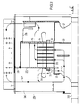
- the asynchronous motor with a squirrel-cage rotor supports the rotor 3 on the shaft 1 with the aid of the hub 2, which in turn is surrounded by the stator 4.
- the motor as a whole is arranged in a housing 5 which is provided with an inlet air opening 6 and an exhaust air opening 7.
- the radial fan 8, to which a flow guide plate 9 is assigned, is located in the area of the exhaust air opening 7.
- a barrier wall 10 is arranged on the air-side end of the stator 4, a slot being provided between the barrier wall and the stator for cooling air to pass through.
- the rotor 3 and the stator 4 are provided with radial slots 11 for the passage of cooling air.
- the shaft 2 is provided with axial slots 12 and axial slots 13, whereby guide channels for a gaseous coolant are formed, the inlet openings of which are located at the end of the hub.
- the guide channels 12 and 13 are partitioned off from one another by a barrier wall 14.
- cooling air is sucked in through the supply air opening 6 by the suction effect of the radial fan 8, so that a coolant flow Q1 results in the area of the supply air opening 6.
- This divides into a partial flow Q2, which flows into the corresponding radial slots 11 via the hub 2.
- a second partial flow Q3 flows around the stator end windings on the supply air side and enters the space surrounding the stator through the slot between the barrier wall 10 and the stator 4 and merges there with the partial flow Q2.
- the coolant flow Q1 then flows around the stator end windings on the exhaust side and leaves as a heated quantity of cooling air Q5 the housing.
- a vortex flow Q4 can form in the area of the machine on the exhaust air side due to the fan action of the rotor 3, which is superimposed on the primary coolant flow Q1 in such a way that it mixes with the coolant flow 1 when it emerges from the stator 4 and in the area of the inlet-side inlet openings of the feed channels 13 branches off from the main coolant flow Q1 again.
- the heat absorbed by the superimposed vortex flow Q4 as it flows through the stator and the rotor is released to the main coolant flow Q1 when it is mixed.
- the shaft 20 is provided with a radially widely projecting hub 21 on which the rotor core 22 rests.
- a barrier wall 23 is arranged within the hub 21.
- the stand 24 is surrounded by a housing 25 which extends essentially in the radial direction and is provided with a passage opening 26.
- the baffle 28 is arranged between the radial fan 27 attached to the hub 21 and the housing 25.
- the machine housing 29 is provided with an inlet air opening 30 and an outlet air opening 31, the inlet air region 36 of the machine housing being partitioned off from the outlet air region by means of the barrier wall 38.
- the radial fan 27 results in a cooling air flow Q7, which flows from the supply air opening 30 to the hub 21 and from there flows through the radial slots 35 in the rotor 22 and in the stator 24 and through the opening 26 and the fan 27 through the Exhaust air opening 31 flows out.
- the hub 21 is formed with a certain projection 32, so that the corresponding radially running hub plates have the function of a radial fan.
- the stator end winding is not provided with a winding shield at the air inlet end of the machine, as is customary per se.
- the hub is additionally provided with a guide plate 37 in this area.
- the blades of a radial fan can also be arranged at this point.
- the axial guide channels 12 and 13, which are also described with reference to the exemplary embodiment according to FIG. 1, can also be located in the rotor laminated core, in particular when the rotor laminated core is seated directly on the shaft.
Landscapes
- Engineering & Computer Science (AREA)
- Power Engineering (AREA)
- Motor Or Generator Cooling System (AREA)
Priority Applications (2)
| Application Number | Priority Date | Filing Date | Title |
|---|---|---|---|
| EP91250189A EP0522210B1 (fr) | 1991-07-12 | 1991-07-12 | Système de refroidissement pour une machine électrique à rotation et machine électrique pour réaliser un tel système |
| DE59106597T DE59106597D1 (de) | 1991-07-12 | 1991-07-12 | Verfahren zum Kühlen einer umlaufenden elektrischen Maschine und elektrische Maschine zur Durchführung des Verfahrens. |
Applications Claiming Priority (1)
| Application Number | Priority Date | Filing Date | Title |
|---|---|---|---|
| EP91250189A EP0522210B1 (fr) | 1991-07-12 | 1991-07-12 | Système de refroidissement pour une machine électrique à rotation et machine électrique pour réaliser un tel système |
Publications (2)
| Publication Number | Publication Date |
|---|---|
| EP0522210A1 true EP0522210A1 (fr) | 1993-01-13 |
| EP0522210B1 EP0522210B1 (fr) | 1995-09-27 |
Family
ID=8208137
Family Applications (1)
| Application Number | Title | Priority Date | Filing Date |
|---|---|---|---|
| EP91250189A Expired - Lifetime EP0522210B1 (fr) | 1991-07-12 | 1991-07-12 | Système de refroidissement pour une machine électrique à rotation et machine électrique pour réaliser un tel système |
Country Status (2)
| Country | Link |
|---|---|
| EP (1) | EP0522210B1 (fr) |
| DE (1) | DE59106597D1 (fr) |
Cited By (12)
| Publication number | Priority date | Publication date | Assignee | Title |
|---|---|---|---|---|
| FR2700646A1 (fr) * | 1993-01-18 | 1994-07-22 | Jacquet Machines Tournantes | Moteur asynchrone à vitesse variable et ventilation forcée. |
| DE19625122A1 (de) * | 1996-06-14 | 1997-12-18 | Siemens Ag | Dynamoelektrische Maschine mit Kreislaufbelüftung |
| WO2002071578A1 (fr) | 2001-03-07 | 2002-09-12 | Hitachi, Ltd. | Machine dynamoelectrique |
| DE10054338C2 (de) * | 2000-11-02 | 2003-11-27 | Antriebstechnik Katt Hessen Gm | Kühlsystem für trägheitsarme rotierende elektrische Maschine |
| US7294943B2 (en) | 2001-03-07 | 2007-11-13 | Hitachi, Ltd. | Electric rotating machine |
| DE102006049188B3 (de) * | 2006-10-14 | 2008-03-27 | Antriebstechnik Katt Hessen Gmbh | Kühlsystem für hochausgenutzte elektrische Maschinen |
| US7411323B2 (en) | 2003-04-16 | 2008-08-12 | Siemens Aktiengesellschaft | Electrical machine having cooled laminated stator and rotor cores and windings |
| DE102009043959A1 (de) | 2008-11-10 | 2010-05-20 | Antriebstechnik Katt Hessen Gmbh | Ständerkühlsystem für eine gehäuselose rotierende elektrische Maschine |
| DE102008064495B3 (de) * | 2008-12-23 | 2010-10-21 | Siemens Aktiengesellschaft | Elektrische Maschine mit mehreren Kühlströmen und Kühlverfahren |
| WO2010081140A3 (fr) * | 2009-01-12 | 2010-10-21 | Power Group International Corporation | Configuration de refroidissement de machine |
| DE102011053299A1 (de) | 2011-09-06 | 2013-03-07 | Antriebstechnik Katt Hessen Gmbh | Kühlsystem für eine hochausgenutzte hochtourige rotierende elektrische Synchronmaschine |
| EP2751911A2 (fr) * | 2011-09-01 | 2014-07-09 | ABB Technology AG | Agencement et procédé pour refroidir une machine électrique |
Citations (4)
| Publication number | Priority date | Publication date | Assignee | Title |
|---|---|---|---|---|
| DE616524C (de) * | 1929-11-03 | 1935-07-31 | Siemens Schuckertwerke Akt Ges | Einrichtung zur Belueftung elektrischer Maschinen mit grosser axialer Laenge |
| CH203227A (de) * | 1937-08-05 | 1939-02-28 | Bbc Brown Boveri & Cie | Elektrische Maschine mit Eigenlüftung. |
| DE1039617B (de) * | 1957-08-21 | 1958-09-25 | Licentia Gmbh | Roehrengekuehlte elektrische Maschine |
| US4682064A (en) * | 1986-03-31 | 1987-07-21 | General Electric Company | Coolant gas flow separator baffle for a dynamoelectric machine |
Family Cites Families (1)
| Publication number | Priority date | Publication date | Assignee | Title |
|---|---|---|---|---|
| DE1281017B (de) * | 1967-01-30 | 1968-10-24 | Licentia Gmbh | Belueftung einer umlaufenden elektrischen Maschine |
-
1991
- 1991-07-12 DE DE59106597T patent/DE59106597D1/de not_active Expired - Lifetime
- 1991-07-12 EP EP91250189A patent/EP0522210B1/fr not_active Expired - Lifetime
Patent Citations (4)
| Publication number | Priority date | Publication date | Assignee | Title |
|---|---|---|---|---|
| DE616524C (de) * | 1929-11-03 | 1935-07-31 | Siemens Schuckertwerke Akt Ges | Einrichtung zur Belueftung elektrischer Maschinen mit grosser axialer Laenge |
| CH203227A (de) * | 1937-08-05 | 1939-02-28 | Bbc Brown Boveri & Cie | Elektrische Maschine mit Eigenlüftung. |
| DE1039617B (de) * | 1957-08-21 | 1958-09-25 | Licentia Gmbh | Roehrengekuehlte elektrische Maschine |
| US4682064A (en) * | 1986-03-31 | 1987-07-21 | General Electric Company | Coolant gas flow separator baffle for a dynamoelectric machine |
Cited By (19)
| Publication number | Priority date | Publication date | Assignee | Title |
|---|---|---|---|---|
| EP0608177A1 (fr) * | 1993-01-18 | 1994-07-27 | Machines Tournantes Jacquet | Moteur asynchrone à vitesse variable et ventilation forcée |
| FR2700646A1 (fr) * | 1993-01-18 | 1994-07-22 | Jacquet Machines Tournantes | Moteur asynchrone à vitesse variable et ventilation forcée. |
| DE19625122A1 (de) * | 1996-06-14 | 1997-12-18 | Siemens Ag | Dynamoelektrische Maschine mit Kreislaufbelüftung |
| DE10054338C2 (de) * | 2000-11-02 | 2003-11-27 | Antriebstechnik Katt Hessen Gm | Kühlsystem für trägheitsarme rotierende elektrische Maschine |
| WO2002071578A1 (fr) | 2001-03-07 | 2002-09-12 | Hitachi, Ltd. | Machine dynamoelectrique |
| EP1367697A4 (fr) * | 2001-03-07 | 2005-10-05 | Hitachi Ltd | Machine dynamoelectrique |
| US7071586B2 (en) | 2001-03-07 | 2006-07-04 | Hitachi, Ltd. | Dynamo-electric machine |
| US7294943B2 (en) | 2001-03-07 | 2007-11-13 | Hitachi, Ltd. | Electric rotating machine |
| US7411323B2 (en) | 2003-04-16 | 2008-08-12 | Siemens Aktiengesellschaft | Electrical machine having cooled laminated stator and rotor cores and windings |
| DE102006049188B3 (de) * | 2006-10-14 | 2008-03-27 | Antriebstechnik Katt Hessen Gmbh | Kühlsystem für hochausgenutzte elektrische Maschinen |
| WO2008043354A2 (fr) | 2006-10-14 | 2008-04-17 | Antriebstechnik Katt Hessen Gmbh | Système de refroidissement pour machines électriques tournantes à haut degré d'utilisation |
| DE102009043959A1 (de) | 2008-11-10 | 2010-05-20 | Antriebstechnik Katt Hessen Gmbh | Ständerkühlsystem für eine gehäuselose rotierende elektrische Maschine |
| EP2230746A2 (fr) | 2008-11-10 | 2010-09-22 | Antriebstechnik Katt Hessen GmbH | Système de refroidissement d`un stator d`une machine électrique tournante sans carcasse |
| DE102008064495B3 (de) * | 2008-12-23 | 2010-10-21 | Siemens Aktiengesellschaft | Elektrische Maschine mit mehreren Kühlströmen und Kühlverfahren |
| US8648505B2 (en) | 2008-12-23 | 2014-02-11 | Siemens Aktiengesellschaft | Electrical machine with multiple cooling flows and cooling method |
| WO2010081140A3 (fr) * | 2009-01-12 | 2010-10-21 | Power Group International Corporation | Configuration de refroidissement de machine |
| EP2751911A2 (fr) * | 2011-09-01 | 2014-07-09 | ABB Technology AG | Agencement et procédé pour refroidir une machine électrique |
| DE102011053299A1 (de) | 2011-09-06 | 2013-03-07 | Antriebstechnik Katt Hessen Gmbh | Kühlsystem für eine hochausgenutzte hochtourige rotierende elektrische Synchronmaschine |
| EP2568576A2 (fr) | 2011-09-06 | 2013-03-13 | Antriebstechnik Katt Hessen GmbH | Système de refroidissement pour une machine synchrone électrique rotative ultrarapide à très haute utilisation |
Also Published As
| Publication number | Publication date |
|---|---|
| DE59106597D1 (de) | 1995-11-02 |
| EP0522210B1 (fr) | 1995-09-27 |
Similar Documents
| Publication | Publication Date | Title |
|---|---|---|
| EP0155405B1 (fr) | Dispositif pour le refroidissement indirect par gaz des enroulements statoriques et/ou pour le refroidissement direct par gaz de paquets de tôles feuilletées d'une machine dynamo-électrique en particulier turbogénérateurs à refroidissement à gaz | |
| DE2252733C3 (de) | Geschlossene gasgekühlte elektrische Maschine | |
| DE102008022105B4 (de) | Flüssigkeitsgekühlte elektrische Maschine sowie Verfahren zur Kühlung einer solchen elektrischen Maschine | |
| DE69923799T2 (de) | Dynamoelektrische maschine | |
| DE1031414B (de) | Verfahren zum Kuehlen axial gerichteter, in die Nuten des Blechpaketes des Laeufers und/oder Staenders einer vollstaendig geschlossenen dynamoelektrischen Maschine eingesetzter Leiter | |
| EP3379696A1 (fr) | Machine à reluctance synchrone | |
| EP0522210B1 (fr) | Système de refroidissement pour une machine électrique à rotation et machine électrique pour réaliser un tel système | |
| DE2334637B2 (de) | Durchzugsbelüftete elektrische Maschine | |
| DE102014018223A1 (de) | Elektrische Maschine, insbesondere Asynchronmaschine | |
| DE10259047A1 (de) | Zentrifugalflüssigkeitskühlsystem für einen Elektromotor | |
| DE3490363T1 (de) | Umlaufende elektrische Maschine | |
| DE112011101406T5 (de) | Wechselstromgenerator mit doppeltem axialem Luftstrom | |
| EP3136549A1 (fr) | Machine a reluctance synchrone | |
| DE10307813B4 (de) | Elektrische Maschine | |
| DE19919040C2 (de) | Synchronmaschine oder Asychronmaschine für große Windenergieanlagen | |
| DE4443427A1 (de) | Elektrische Maschine | |
| DE1014216B (de) | Gasgekuehlte Dynamomaschine | |
| DE2943608A1 (de) | Gasgekuehlter rotor einer elektrodynamischen maschine | |
| DE1036370B (de) | Innen gekuehlte Rotorleiter dynamoelektrischer Maschinen | |
| DE102023103617A1 (de) | Rotor für eine elektrische Maschine | |
| DE3147560C2 (fr) | ||
| DE1033322B (de) | Gaskuehlsystem fuer dynamoelektrische Maschinen | |
| DE102024129046A1 (de) | Kuhlseparatoren fur einen gewickelten rotor | |
| DE2107535C3 (de) | Rotor für eine elektrische Maschine mit einer supraleitenden Wicklung | |
| DE10054338C2 (de) | Kühlsystem für trägheitsarme rotierende elektrische Maschine |
Legal Events
| Date | Code | Title | Description |
|---|---|---|---|
| PUAI | Public reference made under article 153(3) epc to a published international application that has entered the european phase |
Free format text: ORIGINAL CODE: 0009012 |
|
| AK | Designated contracting states |
Kind code of ref document: A1 Designated state(s): CH DE FR GB IT LI |
|
| 17P | Request for examination filed |
Effective date: 19930204 |
|
| 17Q | First examination report despatched |
Effective date: 19940517 |
|
| GRAA | (expected) grant |
Free format text: ORIGINAL CODE: 0009210 |
|
| RIN1 | Information on inventor provided before grant (corrected) |
Inventor name: ZWARG, GUENTER, DIPL.-ING. |
|
| AK | Designated contracting states |
Kind code of ref document: B1 Designated state(s): CH DE FR GB IT LI |
|
| REF | Corresponds to: |
Ref document number: 59106597 Country of ref document: DE Date of ref document: 19951102 |
|
| ET | Fr: translation filed | ||
| ITF | It: translation for a ep patent filed | ||
| GBT | Gb: translation of ep patent filed (gb section 77(6)(a)/1977) |
Effective date: 19951116 |
|
| PLBE | No opposition filed within time limit |
Free format text: ORIGINAL CODE: 0009261 |
|
| STAA | Information on the status of an ep patent application or granted ep patent |
Free format text: STATUS: NO OPPOSITION FILED WITHIN TIME LIMIT |
|
| 26N | No opposition filed | ||
| REG | Reference to a national code |
Ref country code: GB Ref legal event code: IF02 |
|
| REG | Reference to a national code |
Ref country code: CH Ref legal event code: PFA Owner name: SIEMENS AKTIENGESELLSCHAFT Free format text: SIEMENS AKTIENGESELLSCHAFT#WITTELSBACHERPLATZ 2#D-80333 MUENCHEN (DE) -TRANSFER TO- SIEMENS AKTIENGESELLSCHAFT#WITTELSBACHERPLATZ 2#D-80333 MUENCHEN (DE) |
|
| PGFP | Annual fee paid to national office [announced via postgrant information from national office to epo] |
Ref country code: IT Payment date: 20100728 Year of fee payment: 20 Ref country code: FR Payment date: 20100809 Year of fee payment: 20 |
|
| PGFP | Annual fee paid to national office [announced via postgrant information from national office to epo] |
Ref country code: GB Payment date: 20100729 Year of fee payment: 20 |
|
| PGFP | Annual fee paid to national office [announced via postgrant information from national office to epo] |
Ref country code: DE Payment date: 20100920 Year of fee payment: 20 Ref country code: CH Payment date: 20101014 Year of fee payment: 20 |
|
| REG | Reference to a national code |
Ref country code: DE Ref legal event code: R071 Ref document number: 59106597 Country of ref document: DE |
|
| REG | Reference to a national code |
Ref country code: DE Ref legal event code: R071 Ref document number: 59106597 Country of ref document: DE |
|
| REG | Reference to a national code |
Ref country code: CH Ref legal event code: PL |
|
| REG | Reference to a national code |
Ref country code: GB Ref legal event code: PE20 Expiry date: 20110711 |
|
| PG25 | Lapsed in a contracting state [announced via postgrant information from national office to epo] |
Ref country code: GB Free format text: LAPSE BECAUSE OF EXPIRATION OF PROTECTION Effective date: 20110711 |
|
| PG25 | Lapsed in a contracting state [announced via postgrant information from national office to epo] |
Ref country code: DE Free format text: LAPSE BECAUSE OF EXPIRATION OF PROTECTION Effective date: 20110713 |