EP0522421A1 - Procédé et transmission pour machines textiles pour éviter l'enroulage en ruban lors du bobinage de fils - Google Patents
Procédé et transmission pour machines textiles pour éviter l'enroulage en ruban lors du bobinage de fils Download PDFInfo
- Publication number
- EP0522421A1 EP0522421A1 EP92111070A EP92111070A EP0522421A1 EP 0522421 A1 EP0522421 A1 EP 0522421A1 EP 92111070 A EP92111070 A EP 92111070A EP 92111070 A EP92111070 A EP 92111070A EP 0522421 A1 EP0522421 A1 EP 0522421A1
- Authority
- EP
- European Patent Office
- Prior art keywords
- belt
- pulley
- designed
- transmission
- transmission according
- Prior art date
- Legal status (The legal status is an assumption and is not a legal conclusion. Google has not performed a legal analysis and makes no representation as to the accuracy of the status listed.)
- Granted
Links
Images


Classifications
-
- F—MECHANICAL ENGINEERING; LIGHTING; HEATING; WEAPONS; BLASTING
- F16—ENGINEERING ELEMENTS AND UNITS; GENERAL MEASURES FOR PRODUCING AND MAINTAINING EFFECTIVE FUNCTIONING OF MACHINES OR INSTALLATIONS; THERMAL INSULATION IN GENERAL
- F16H—GEARING
- F16H9/00—Gearings for conveying rotary motion with variable gear ratio, or for reversing rotary motion, by endless flexible members
- F16H9/02—Gearings for conveying rotary motion with variable gear ratio, or for reversing rotary motion, by endless flexible members without members having orbital motion
- F16H9/04—Gearings for conveying rotary motion with variable gear ratio, or for reversing rotary motion, by endless flexible members without members having orbital motion using belts, V-belts, or ropes
- F16H9/12—Gearings for conveying rotary motion with variable gear ratio, or for reversing rotary motion, by endless flexible members without members having orbital motion using belts, V-belts, or ropes engaging a pulley built-up out of relatively axially-adjustable parts in which the belt engages the opposite flanges of the pulley directly without interposed belt-supporting members
- F16H9/14—Gearings for conveying rotary motion with variable gear ratio, or for reversing rotary motion, by endless flexible members without members having orbital motion using belts, V-belts, or ropes engaging a pulley built-up out of relatively axially-adjustable parts in which the belt engages the opposite flanges of the pulley directly without interposed belt-supporting members using only one pulley built-up out of adjustable conical parts
-
- B—PERFORMING OPERATIONS; TRANSPORTING
- B65—CONVEYING; PACKING; STORING; HANDLING THIN OR FILAMENTARY MATERIAL
- B65H—HANDLING THIN OR FILAMENTARY MATERIAL, e.g. SHEETS, WEBS, CABLES
- B65H54/00—Winding, coiling, or depositing filamentary material
- B65H54/02—Winding and traversing material on to reels, bobbins, tubes, or like package cores or formers
- B65H54/38—Arrangements for preventing ribbon winding ; Arrangements for preventing irregular edge forming, e.g. edge raising or yarn falling from the edge
-
- G—PHYSICS
- G21—NUCLEAR PHYSICS; NUCLEAR ENGINEERING
- G21C—NUCLEAR REACTORS
- G21C19/00—Arrangements for treating, for handling, or for facilitating the handling of, fuel or other materials which are used within the reactor, e.g. within its pressure vessel
- G21C19/42—Reprocessing of irradiated fuel
-
- G—PHYSICS
- G21—NUCLEAR PHYSICS; NUCLEAR ENGINEERING
- G21C—NUCLEAR REACTORS
- G21C19/00—Arrangements for treating, for handling, or for facilitating the handling of, fuel or other materials which are used within the reactor, e.g. within its pressure vessel
- G21C19/42—Reprocessing of irradiated fuel
- G21C19/44—Reprocessing of irradiated fuel of irradiated solid fuel
-
- B—PERFORMING OPERATIONS; TRANSPORTING
- B65—CONVEYING; PACKING; STORING; HANDLING THIN OR FILAMENTARY MATERIAL
- B65H—HANDLING THIN OR FILAMENTARY MATERIAL, e.g. SHEETS, WEBS, CABLES
- B65H2701/00—Handled material; Storage means
- B65H2701/30—Handled filamentary material
- B65H2701/31—Textiles threads or artificial strands of filaments
-
- Y—GENERAL TAGGING OF NEW TECHNOLOGICAL DEVELOPMENTS; GENERAL TAGGING OF CROSS-SECTIONAL TECHNOLOGIES SPANNING OVER SEVERAL SECTIONS OF THE IPC; TECHNICAL SUBJECTS COVERED BY FORMER USPC CROSS-REFERENCE ART COLLECTIONS [XRACs] AND DIGESTS
- Y02—TECHNOLOGIES OR APPLICATIONS FOR MITIGATION OR ADAPTATION AGAINST CLIMATE CHANGE
- Y02E—REDUCTION OF GREENHOUSE GAS [GHG] EMISSIONS, RELATED TO ENERGY GENERATION, TRANSMISSION OR DISTRIBUTION
- Y02E30/00—Energy generation of nuclear origin
- Y02E30/30—Nuclear fission reactors
Definitions
- the present invention relates to a transmission according to the preamble of claim 1.
- Gearboxes with belt drives are known from the prior art, in which the gear ratio can be changed. This is controlled by changing the belt tension or by deflecting the belt transversely to the direction of travel, whereby a belt pulley of the transmission designed as a spring washer changes its effective diameter for the belt.
- Such gears can be used in a variety of ways, because here the transmission ratio of the gears can be changed continuously within certain limits.
- Such gears have the disadvantage that wear of the belt changes the gear ratio during operation while the gearing remains the same. Readjustment is necessary if a certain gear ratio is to be maintained.
- the invention is described by way of example in an application in textile machines as a disturbing gear, where it can be used particularly advantageously because here, by constantly changing the gear ratio, a particularly high wear load is present and the desired gear ratio must be reliably maintained.
- jamming devices are known in practice, in which a thread which is fed at a constant speed to a winding device for forming a bobbin is laid on the bobbin with a different traversing speed. As a result, the Crosshair angle changed and the development of image windings is prevented.
- the known RU 14 rotor spinning machine from Schubert & Salzer AG, Ingolstadt, Germany, discloses a gear unit in which the speed of the thread guide gear and thereby the speed of the back and forth thread guide movement is changed in that an interference gear is connected upstream, which as a V-belt gear with Control disc is formed.
- the effective diameter of the control pulley becomes changed so that the thread guide gear is driven with a changed drive speed.
- changes in the transmission ratio can occur in this transmission, as a result of which the predetermined average transmission ratio and thus the desired average crossing angle change.
- the wear of the belt is less noticeable through elongation of the belt but through a change in its flanks.
- the width of the belt changes so that it becomes narrower.
- the object of the present invention is to propose a transmission which avoids the disadvantages of the prior art and which is of less expensive and simpler design and, in particular, can also be used as a fault transmission which is simple in design, is inexpensive and maintenance-free.
- This object is achieved according to the invention by designing a transmission and a belt in accordance with the features of claims 1 and 13.
- Another object of the invention is to propose a belt that can be used in the transmission according to the invention.
- the inventive design of the spur gear ensures that the flank wear of the belt has no influence on the transmission ratio of the belt drive.
- the flank wear is compensated by the spring washer without changing the effective diameter on which the belt runs.
- the spring washer compensates for the lost width and the belt tension is retained.
- the belt of the fault transmission according to the invention works together with the drive pulley with a different running surface than with the driven pulley of the belt drive or vice versa.
- the transmission ratio of the belt drive is independent of the wear on the belt, because the flank wear on the belt cannot affect the effective diameter of a flat belt or toothed belt pulley.
- the effective diameter of the two, which determine the transmission ratio Pulleys, remain constant.
- the translation of the belt drive changes in a controlled manner solely through the controllable tensioning pulley. independence from wear is achieved because the spring washer automatically compensates for flank wear by the spring controlling the pulley halves and because the pulley works with a running surface of the belt that is not subject to wear.
- the belt cooperates with a pulley which is designed as a toothed belt pulley.
- a pulley which is designed as a toothed belt pulley.
- the toothed belt pulley works together with a lateral surface of the belt that is not affected by belt wear.
- the toothed belt pulley has the advantage that higher gear dimensions and speeds are otherwise the same Forces can be transmitted, and that the belt can therefore be made narrower than a flat belt.
- a particularly favorable embodiment of the transmission is achieved if the drive pulley is designed as a toothed belt pulley and the driven pulley as a spring washer. As a result, the transmission can be made particularly compact.
- the tensioning roller is also designed so that it does not work together with the V-belt-like flanks of the belt. This is the case, for example, if it is designed as a flat belt pulley. This ensures that the belt also rotates at a constant effective diameter on the tensioning roller, so that the mean tension of the belt or the mean transmission ratio remains constant.
- the spring washer is equipped with 2 movable disk halves. It is thereby achieved that the drive and drive are still in alignment with one another by changing the transmission ratio.
- the transmission can be made particularly compact if one or more drive wheels for driving a thread guide transmission is assigned to the driven pulley on a common shaft.
- the Tension roller for changing the belt tension is actuated by means of a linkage. Particularly advantageous via a pull linkage.
- the gear is particularly easy to adjust if the length of the linkage can be changed using a turnbuckle nut.
- the belt has at least on one of its outer surfaces a running surface with which it cooperates with a pulley and the tensioning pulley. It is particularly advantageous if the running surface of the belt is provided with a toothing with which it works together with a toothed belt pulley. This makes it possible to transmit large forces and to make the belt narrow at the same time.
- the belt is designed as a wide V-belt, which means that it can advantageously work both with the spring washer, which is to be regarded as a V-belt pulley, and also has a favorable width for working with a flat belt pulley.
- flanks of the belt have different wedge angles.
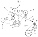
- FIG. 1 shows a schematic representation of a transmission according to the invention in the form of a spur transmission 1.
- This consists of a drive pulley 11, a driven pulley 12, which is designed as a spring washer, a tension roller 13 and a belt 14.
- the driven pulley 12 is together with two toothed belt pulleys 17 a shaft 18 mounted. Be over the two toothed belt pulleys 17 simultaneously driven two thread guide gear 2.
- the belt of the interference gear 1 is tensioned more or less via the tensioning roller 13.
- the two pulley halves of the driven pulley 12 designed as a spring washer are moved apart or towards one another, as a result of which the belt 14 plunges more or less deeply into the wedge of the spring washer.
- the thread guide gear 2 are thereby driven at a different speed. The result of this is that the speed of the thread guide, not shown here, is changed and, in order to prevent image windings, the thread is deposited on the bobbin with a changing or changed thread crossing angle.
- the change by means of the tensioning roller 13 takes place via a linkage 3.
- the tensioning roller 13 sits on an arm of a two-armed lever 31.
- the deflection of the tensioning roller 13 is caused by the pull rod 32, which engages at the other end of the lever 31, controlled.
- the movement of the pull rod 32 required for the adjustment of the tensioning roller is generated by an eccentric gear (35).
- the eccentric 351 is seated on a relatively slowly rotating shaft 352, which can be, for example, the feed shaft of an open-end spinning machine.
- the even deflection of the tension pulley, as would be caused by a normal eccentric, is in turn varied in the present eccentric gear by superimposing another movement.
- a sleeve which is mounted on the eccentric 351 and in turn is eccentric and which controls the pull rod 32 is rotated, as a result of which an additional movement acts on the pull rod 32.
- the adjustment of the belt tension is so uneven that practically no more regularities occur in the thread guide movement.
- the linkage 3 has a turnbuckle 33 with which the length of the pull rod 32 is adjusted.
- a turnbuckle 33 with which the length of the pull rod 32 is adjusted.
- the drive pulley 11 of the interference gear 1 is designed as a toothed belt pulley, as is the tensioning pulley 13.
- the belt 14 therefore has on its inner one Shell surface 143 a toothing 142 with which he works with the two toothed belt pulleys.
- the belt also cooperates with the driven pulley 12, which is designed as a spring washer, via its flanks 141, which are designed in the manner of a V-belt, like a V-belt.
- the drive pulley 11 could also be designed as a spring washer and the driven pulley 12 as a toothed belt pulley.
- a belt used in such a transmission has a tread on at least one of its outer surfaces, with which it works with a flat belt pulley.
- the pulleys work together with the inner lateral surface and the belt flanks, while the tensioning roller rolls on the outer lateral surface of the belt.
- the tensioning roller can be designed both as a flat belt pulley and as a toothed belt pulley, in the latter case when the belt also has teeth on its outer circumferential surface.
- the effect of the invention is generally based on the fact that, starting from the realization that the wear of the belt relevant to the function of the transmission reduces the width of the belt in the region of its flanks, the belt with the tread which has been changed by wear cooperates with a spring washer, while the other pulleys work with another tread of the belt, whereby this applies particularly to the other traction sheave.
- the effect of belt wear on the gearbox is not so great when using a V-belt pulley as a tension pulley if it is arranged in the empty run of the belt drive.
- the tensioning roller does not work together with the flanks of the belt.
- FIG. 2 shows a side view of a belt drive designed according to the invention, with a spring washer 121, a belt 14 designed as a toothed belt, a toothed belt pulley 17 and a tensioning roller 13 designed as a toothed belt pulley.
- the tensioning roller 13 is fastened to a lever 31 which, by pivoting the tensioning roller 13 moved such that the belt is more or less deflected.
- the flanks 141 of the belt 14 are formed like a V-belt and work with the as a spring washer 121 trained V-belt pulley together.
- FIG 3 shows a belt drive of an interference transmission designed according to the invention in section.
- the belt 14 is designed as a toothed belt, the toothing 142 being arranged on its inner lateral surface 143.
- the belt 14 cooperates with a toothed belt pulley 17 via its toothing. With its flanks 141, the belt engages in a wedge gap of a spring washer 121.
- the spring washer 121 is a spring washer that opens on one side educated. A deeper penetration of the belt 14 into the spring washer 121 caused by higher belt tension causes its movable pulley half 122 to move to the right, the belt also moving to the right at the same time.
- a sufficiently wide configuration of the toothed belt pulley 17 ensures that such an offset of the belt has no negative effects on the belt drive. The same also applies to the design of the tensioning roller 13. Which of the two belt pulleys (17, 121) is the drive pulley and which driven pulley of the belt drive is irrelevant to the present invention.
- Figures 4 to 6 show different forms of construction of a belt according to the invention.
- the belt 14 of Figure 4 is designed as a wide V-belt and has two flanks 141 and a toothing 142 with which it can work with a toothed belt pulley for cooperation with a V-belt pulley.
- the belt 14 of FIG. 5 also has 2 flanks 141, for example to work with a spring washer, and a toothing 142 on both its outer lateral surface 145 and on its inner lateral surface 143.
- the flanks of the outer toothing 144 are not, for example, in this belt 14 suitable for working with a V-belt pulley.
- Figure 6 shows a strap 14 with a particularly thick back.
- FIG. 7 shows a side view of part of a belt 14 with a toothing 142 which is arranged on the inner circumferential surface of the belt.
- the entire side surface of the belt 14 forms the flank 141 with which it cooperates with a V-belt pulley.
- the use of the invention is not only limited to an open-end spinning / winding machine, which is mentioned by way of example, but is also possible in other textile machines, where a back and forth laying of a thread must be varied in order to avoid filing.
- the invention is described by way of example on a spur gear for a spinning / winding machine. However, it is not limited to this alone.
- a transmission can be used in all drives in which the speed or the gear ratio can be varied but must remain as constant as possible after the adjustment.
- changing points in drives of textile or machine tools can also be replaced or those with toothed belt pulleys.
- the transmission ratio of the transmission according to the invention remains reliably constant during operation, such a transmission according to the invention can also be used at transmission points that could not previously be equipped with a cheap and variable variable speed transmission.
- such a gearbox can replace the changeover point that controls the tension delay in rotor spinning machines. As a result, the expensive replacement gear sets can be saved.
- the invention is also suitable to replace the known continuously variable transmissions very cost-effectively, which work with conical disks and a special chain and also ensure a constant transmission ratio, but with much greater effort.
- Experiments with the transmission according to the invention have shown that it is possible to set a rotational speed over several To keep practically constant for months with a speed deviation of less than 1%.
Landscapes
- Engineering & Computer Science (AREA)
- General Engineering & Computer Science (AREA)
- Physics & Mathematics (AREA)
- Textile Engineering (AREA)
- Mechanical Engineering (AREA)
- Plasma & Fusion (AREA)
- High Energy & Nuclear Physics (AREA)
- Devices For Conveying Motion By Means Of Endless Flexible Members (AREA)
- Transmissions By Endless Flexible Members (AREA)
Applications Claiming Priority (2)
| Application Number | Priority Date | Filing Date | Title |
|---|---|---|---|
| DE4121781A DE4121781A1 (de) | 1991-07-01 | 1991-07-01 | Getriebe fuer textilmaschinen insbesondere zum verhindern von bildwicklungen beim aufwinden von faeden |
| DE4121781 | 1992-07-01 |
Publications (2)
| Publication Number | Publication Date |
|---|---|
| EP0522421A1 true EP0522421A1 (fr) | 1993-01-13 |
| EP0522421B1 EP0522421B1 (fr) | 1995-02-15 |
Family
ID=6435194
Family Applications (1)
| Application Number | Title | Priority Date | Filing Date |
|---|---|---|---|
| EP92111070A Expired - Lifetime EP0522421B1 (fr) | 1991-07-01 | 1992-06-30 | Procédé et transmission pour machines textiles pour éviter l'enroulage en ruban lors du bobinage de fils |
Country Status (4)
| Country | Link |
|---|---|
| US (1) | US5277668A (fr) |
| EP (1) | EP0522421B1 (fr) |
| CZ (1) | CZ288892B6 (fr) |
| DE (2) | DE4121781A1 (fr) |
Cited By (2)
| Publication number | Priority date | Publication date | Assignee | Title |
|---|---|---|---|---|
| CN1057737C (zh) * | 1994-04-14 | 2000-10-25 | 皮亚乔公司 | 无级传动脚踏机动车的驱动皮带轮组件 |
| JP2012500765A (ja) * | 2008-08-22 | 2012-01-12 | ペムコ ブルッヘ ベーヴィベーアー | V2o5−低含有乃至非含有ほうろう |
Families Citing this family (6)
| Publication number | Priority date | Publication date | Assignee | Title |
|---|---|---|---|---|
| DE19745735A1 (de) * | 1997-10-16 | 1999-04-22 | Bayerische Motoren Werke Ag | Hilfsaggregate-Antrieb für eine Brennkraftmaschine, mit variabler Übersetzung |
| GB9820984D0 (en) | 1998-09-25 | 1998-11-18 | Hammerbeck John P R | A variable speed drive |
| FR2791112B1 (fr) * | 1999-03-19 | 2001-06-01 | Colmant Cuvelier | Dispositif de transmission a entrainement mixte |
| DE10209393A1 (de) * | 2002-03-02 | 2003-09-11 | Rieter Ingolstadt Spinnerei | Regelscheibe für ein Riemengetriebe |
| FR2932128B1 (fr) * | 2008-06-04 | 2010-06-11 | France Reducteurs | Dispositif de variation de vitesse pour engin automoteur a conducteur embarque |
| DE102017003376A1 (de) | 2017-04-06 | 2018-10-11 | Saurer Ag | Verfahren zum Betrieb einer Schiffchen-Stickmaschine mit Gatter und Riemenantrieb, sowie Riemenantrieb mit Spanneinrichtung |
Citations (9)
| Publication number | Priority date | Publication date | Assignee | Title |
|---|---|---|---|---|
| US1822935A (en) * | 1928-03-26 | 1931-09-15 | Reeves Pulley Company Of Colum | Variable speed unit |
| US1966259A (en) * | 1933-03-15 | 1934-07-10 | Foster Machine Co | Package winding machine |
| US2091902A (en) * | 1935-02-18 | 1937-08-31 | Universal Winding Co | Winding machine |
| US2437540A (en) * | 1944-06-26 | 1948-03-09 | Chain Belt Co | Variable-speed transmission |
| US2868474A (en) * | 1955-11-02 | 1959-01-13 | Coulter & Mckenzie Machine Co | Multiple speed coiler |
| DE1760524A1 (de) * | 1968-05-30 | 1971-12-30 | Weller Maschf Heinz | Verfahren und Vorrichtung zur Steuerung der hin- und hergehenden Fadenfuehrerbewegung von Aufspuleinrichtungen zum Aufspulen von Faeden auf Kreuzspulen |
| FR2253953A1 (en) * | 1973-12-06 | 1975-07-04 | Fmc Corp | Steplessly adjustable vee belt drive - has additional belt acting against outside of main one for auxiliary drive |
| FR2287406A1 (fr) * | 1974-10-08 | 1976-05-07 | Schweiter Ag Maschf | Bobinoir a dispositif pour eviter la formation d'enroulements a nappes identiques |
| US4515576A (en) * | 1981-02-13 | 1985-05-07 | Wiens William S | Variable speed transmission |
Family Cites Families (4)
| Publication number | Priority date | Publication date | Assignee | Title |
|---|---|---|---|---|
| US2079351A (en) * | 1935-11-19 | 1937-05-04 | Oscar I Judelshon | Drive belt |
| DE2200686C3 (de) * | 1972-01-07 | 1986-01-02 | Schubert & Salzer Maschinenfabrik Ag, 8070 Ingolstadt | Offenend-Spinnmaschine |
| CS163962B1 (fr) * | 1972-11-03 | 1975-11-07 | ||
| US4685898A (en) * | 1984-03-01 | 1987-08-11 | Wiens William S | Variable speed transmission |
-
1991
- 1991-07-01 DE DE4121781A patent/DE4121781A1/de not_active Withdrawn
-
1992
- 1992-06-29 CZ CS19922020A patent/CZ288892B6/cs not_active IP Right Cessation
- 1992-06-30 DE DE59201392T patent/DE59201392D1/de not_active Expired - Fee Related
- 1992-06-30 EP EP92111070A patent/EP0522421B1/fr not_active Expired - Lifetime
- 1992-07-01 US US07/907,356 patent/US5277668A/en not_active Expired - Fee Related
Patent Citations (9)
| Publication number | Priority date | Publication date | Assignee | Title |
|---|---|---|---|---|
| US1822935A (en) * | 1928-03-26 | 1931-09-15 | Reeves Pulley Company Of Colum | Variable speed unit |
| US1966259A (en) * | 1933-03-15 | 1934-07-10 | Foster Machine Co | Package winding machine |
| US2091902A (en) * | 1935-02-18 | 1937-08-31 | Universal Winding Co | Winding machine |
| US2437540A (en) * | 1944-06-26 | 1948-03-09 | Chain Belt Co | Variable-speed transmission |
| US2868474A (en) * | 1955-11-02 | 1959-01-13 | Coulter & Mckenzie Machine Co | Multiple speed coiler |
| DE1760524A1 (de) * | 1968-05-30 | 1971-12-30 | Weller Maschf Heinz | Verfahren und Vorrichtung zur Steuerung der hin- und hergehenden Fadenfuehrerbewegung von Aufspuleinrichtungen zum Aufspulen von Faeden auf Kreuzspulen |
| FR2253953A1 (en) * | 1973-12-06 | 1975-07-04 | Fmc Corp | Steplessly adjustable vee belt drive - has additional belt acting against outside of main one for auxiliary drive |
| FR2287406A1 (fr) * | 1974-10-08 | 1976-05-07 | Schweiter Ag Maschf | Bobinoir a dispositif pour eviter la formation d'enroulements a nappes identiques |
| US4515576A (en) * | 1981-02-13 | 1985-05-07 | Wiens William S | Variable speed transmission |
Cited By (2)
| Publication number | Priority date | Publication date | Assignee | Title |
|---|---|---|---|---|
| CN1057737C (zh) * | 1994-04-14 | 2000-10-25 | 皮亚乔公司 | 无级传动脚踏机动车的驱动皮带轮组件 |
| JP2012500765A (ja) * | 2008-08-22 | 2012-01-12 | ペムコ ブルッヘ ベーヴィベーアー | V2o5−低含有乃至非含有ほうろう |
Also Published As
| Publication number | Publication date |
|---|---|
| EP0522421B1 (fr) | 1995-02-15 |
| CS202092A3 (en) | 1993-01-13 |
| CZ288892B6 (cs) | 2001-09-12 |
| US5277668A (en) | 1994-01-11 |
| DE4121781A1 (de) | 1993-01-21 |
| DE59201392D1 (de) | 1995-03-23 |
Similar Documents
| Publication | Publication Date | Title |
|---|---|---|
| EP0165511B1 (fr) | Dispositif pour bobiner un fil livré à vitesse constante sur une bobine conique | |
| EP0114642B1 (fr) | Machine à bobiner | |
| DE8916288U1 (de) | Aufspulmaschine | |
| CH691904A5 (de) | Vorrichtung zur Einstellung der Spannung eines Fadens. | |
| DE112007001233B4 (de) | Verfahren und Vorrichtung zur Garnchangierung bei der Aufwicklung des Garns auf eine Spule | |
| EP0210183B1 (fr) | Metier a filer open-end possedant une pluralite de points de filature, dont les elements de filature sont entraines conjointement par un entrainement commun | |
| EP0036002B1 (fr) | Dispositif de commande de la vitesse de rotation des broches d'un banc a broches | |
| EP0522421B1 (fr) | Procédé et transmission pour machines textiles pour éviter l'enroulage en ruban lors du bobinage de fils | |
| DE3028316C2 (de) | Vorrichtung zum Verringern der Zugkraft eines unter Fadenballonbildung aus der Zwirnspindel einer Doppeldrahtzwirnmaschine austretenden, zur Herstellung eines Färbewickels bestimmten Fadens | |
| DE2609156A1 (de) | Verfahren und vorrichtung zum trennen des vorgarnes beim abziehen in einer vorspinnmaschine | |
| DE7629726U1 (de) | Triebwerk fuer rapiere in rapierwebmaschinen | |
| DE3801880C3 (de) | Streckwerk in Spinnereimaschinen, insbesondere Regulierstreckwerk in Strecken | |
| DE69200807T2 (de) | Selbsteinstellende Mehrfachdrahtziehmaschine. | |
| DE1244028B (de) | Steuer- und Schaltvorrichtung an mechanisch oder hydraulisch angetriebenen Changiereinrichtungen bei Spinn-, Spul- und insbesondere Ringzwirnmaschinen | |
| DE902700C (de) | Stufenlos regelbares Getriebe | |
| EP0114641A1 (fr) | Machine à bobiner avec guide-fil à pales | |
| DE2901497A1 (de) | Aufwickelvorrichtung zum direkten ziehen von glasfaser aus einer duesenplatte zur herstellung einer praezisionswicklung | |
| DE1510768C (de) | Aus Herzscheibe und Herzschei benhebel bestehende Changiervorrichtung für Spinn und Zwirnmaschinen | |
| DE227801C (fr) | ||
| CH439036A (de) | Kreuzspulmaschine | |
| DD139829B1 (de) | Aufspulvorrichtung mit changiereinrichtung | |
| DE19515476A1 (de) | Antrieb für Spindeln einer Spinn- oder Zwirnmaschine | |
| DE1535026A1 (de) | Wickelmaschine,insbesondere Vorspinnmaschine,Flyer od.dgl. | |
| EP0752385A1 (fr) | Méthode et dispositif de va-et-vient pour des matériaux filiforms ou des rubans | |
| DE4118086A1 (de) | Legemaschine |
Legal Events
| Date | Code | Title | Description |
|---|---|---|---|
| PUAI | Public reference made under article 153(3) epc to a published international application that has entered the european phase |
Free format text: ORIGINAL CODE: 0009012 |
|
| 17P | Request for examination filed |
Effective date: 19920630 |
|
| AK | Designated contracting states |
Kind code of ref document: A1 Designated state(s): CH DE FR IT LI |
|
| 17Q | First examination report despatched |
Effective date: 19940718 |
|
| RAP1 | Party data changed (applicant data changed or rights of an application transferred) |
Owner name: RIETER INGOLSTADT SPINNEREIMASCHINENBAU AKTIENGESE |
|
| GRAA | (expected) grant |
Free format text: ORIGINAL CODE: 0009210 |
|
| AK | Designated contracting states |
Kind code of ref document: B1 Designated state(s): CH DE FR IT LI |
|
| PG25 | Lapsed in a contracting state [announced via postgrant information from national office to epo] |
Ref country code: FR Effective date: 19950215 |
|
| REF | Corresponds to: |
Ref document number: 59201392 Country of ref document: DE Date of ref document: 19950323 |
|
| ITF | It: translation for a ep patent filed | ||
| PG25 | Lapsed in a contracting state [announced via postgrant information from national office to epo] |
Ref country code: LI Effective date: 19950630 Ref country code: CH Effective date: 19950630 |
|
| EN | Fr: translation not filed | ||
| PLBE | No opposition filed within time limit |
Free format text: ORIGINAL CODE: 0009261 |
|
| STAA | Information on the status of an ep patent application or granted ep patent |
Free format text: STATUS: NO OPPOSITION FILED WITHIN TIME LIMIT |
|
| 26N | No opposition filed | ||
| REG | Reference to a national code |
Ref country code: CH Ref legal event code: PL |
|
| PG25 | Lapsed in a contracting state [announced via postgrant information from national office to epo] |
Ref country code: IT Free format text: LAPSE BECAUSE OF NON-PAYMENT OF DUE FEES;WARNING: LAPSES OF ITALIAN PATENTS WITH EFFECTIVE DATE BEFORE 2007 MAY HAVE OCCURRED AT ANY TIME BEFORE 2007. THE CORRECT EFFECTIVE DATE MAY BE DIFFERENT FROM THE ONE RECORDED. Effective date: 20050630 |
|
| PGFP | Annual fee paid to national office [announced via postgrant information from national office to epo] |
Ref country code: DE Payment date: 20060821 Year of fee payment: 15 |
|
| PG25 | Lapsed in a contracting state [announced via postgrant information from national office to epo] |
Ref country code: DE Free format text: LAPSE BECAUSE OF NON-PAYMENT OF DUE FEES Effective date: 20080101 |