EP0522536B1 - Installation d'extrusion-soufflage - Google Patents
Installation d'extrusion-soufflage Download PDFInfo
- Publication number
- EP0522536B1 EP0522536B1 EP92111603A EP92111603A EP0522536B1 EP 0522536 B1 EP0522536 B1 EP 0522536B1 EP 92111603 A EP92111603 A EP 92111603A EP 92111603 A EP92111603 A EP 92111603A EP 0522536 B1 EP0522536 B1 EP 0522536B1
- Authority
- EP
- European Patent Office
- Prior art keywords
- film
- running direction
- webs
- flat
- film webs
- Prior art date
- Legal status (The legal status is an assumption and is not a legal conclusion. Google has not performed a legal analysis and makes no representation as to the accuracy of the status listed.)
- Expired - Lifetime
Links
- 238000009434 installation Methods 0.000 title claims 9
- 238000000071 blow moulding Methods 0.000 title 1
- 238000004804 winding Methods 0.000 claims description 24
- 238000000034 method Methods 0.000 claims description 10
- 238000004519 manufacturing process Methods 0.000 claims description 6
- 238000000926 separation method Methods 0.000 claims description 4
- 238000011144 upstream manufacturing Methods 0.000 claims description 3
- 230000008901 benefit Effects 0.000 description 5
- 238000011161 development Methods 0.000 description 3
- 230000018109 developmental process Effects 0.000 description 3
- 229920000642 polymer Polymers 0.000 description 3
- 238000010096 film blowing Methods 0.000 description 2
- 239000011888 foil Substances 0.000 description 2
- 239000008187 granular material Substances 0.000 description 2
- 238000005266 casting Methods 0.000 description 1
- 239000002131 composite material Substances 0.000 description 1
- 238000001125 extrusion Methods 0.000 description 1
- 238000002347 injection Methods 0.000 description 1
- 239000007924 injection Substances 0.000 description 1
- 238000002844 melting Methods 0.000 description 1
- 230000008018 melting Effects 0.000 description 1
- 238000005096 rolling process Methods 0.000 description 1
- 239000007921 spray Substances 0.000 description 1
- 238000009966 trimming Methods 0.000 description 1
- 238000003466 welding Methods 0.000 description 1
Images


Classifications
-
- B—PERFORMING OPERATIONS; TRANSPORTING
- B65—CONVEYING; PACKING; STORING; HANDLING THIN OR FILAMENTARY MATERIAL
- B65H—HANDLING THIN OR FILAMENTARY MATERIAL, e.g. SHEETS, WEBS, CABLES
- B65H23/00—Registering, tensioning, smoothing or guiding webs
- B65H23/04—Registering, tensioning, smoothing or guiding webs longitudinally
- B65H23/32—Arrangements for turning or reversing webs
-
- B—PERFORMING OPERATIONS; TRANSPORTING
- B29—WORKING OF PLASTICS; WORKING OF SUBSTANCES IN A PLASTIC STATE IN GENERAL
- B29C—SHAPING OR JOINING OF PLASTICS; SHAPING OF MATERIAL IN A PLASTIC STATE, NOT OTHERWISE PROVIDED FOR; AFTER-TREATMENT OF THE SHAPED PRODUCTS, e.g. REPAIRING
- B29C48/00—Extrusion moulding, i.e. expressing the moulding material through a die or nozzle which imparts the desired form; Apparatus therefor
- B29C48/03—Extrusion moulding, i.e. expressing the moulding material through a die or nozzle which imparts the desired form; Apparatus therefor characterised by the shape of the extruded material at extrusion
- B29C48/09—Articles with cross-sections having partially or fully enclosed cavities, e.g. pipes or channels
- B29C48/10—Articles with cross-sections having partially or fully enclosed cavities, e.g. pipes or channels flexible, e.g. blown foils
-
- B—PERFORMING OPERATIONS; TRANSPORTING
- B29—WORKING OF PLASTICS; WORKING OF SUBSTANCES IN A PLASTIC STATE IN GENERAL
- B29C—SHAPING OR JOINING OF PLASTICS; SHAPING OF MATERIAL IN A PLASTIC STATE, NOT OTHERWISE PROVIDED FOR; AFTER-TREATMENT OF THE SHAPED PRODUCTS, e.g. REPAIRING
- B29C48/00—Extrusion moulding, i.e. expressing the moulding material through a die or nozzle which imparts the desired form; Apparatus therefor
- B29C48/001—Combinations of extrusion moulding with other shaping operations
- B29C48/0018—Combinations of extrusion moulding with other shaping operations combined with shaping by orienting, stretching or shrinking, e.g. film blowing
-
- B—PERFORMING OPERATIONS; TRANSPORTING
- B29—WORKING OF PLASTICS; WORKING OF SUBSTANCES IN A PLASTIC STATE IN GENERAL
- B29C—SHAPING OR JOINING OF PLASTICS; SHAPING OF MATERIAL IN A PLASTIC STATE, NOT OTHERWISE PROVIDED FOR; AFTER-TREATMENT OF THE SHAPED PRODUCTS, e.g. REPAIRING
- B29C48/00—Extrusion moulding, i.e. expressing the moulding material through a die or nozzle which imparts the desired form; Apparatus therefor
- B29C48/001—Combinations of extrusion moulding with other shaping operations
- B29C48/0019—Combinations of extrusion moulding with other shaping operations combined with shaping by flattening, folding or bending
-
- B—PERFORMING OPERATIONS; TRANSPORTING
- B29—WORKING OF PLASTICS; WORKING OF SUBSTANCES IN A PLASTIC STATE IN GENERAL
- B29C—SHAPING OR JOINING OF PLASTICS; SHAPING OF MATERIAL IN A PLASTIC STATE, NOT OTHERWISE PROVIDED FOR; AFTER-TREATMENT OF THE SHAPED PRODUCTS, e.g. REPAIRING
- B29C48/00—Extrusion moulding, i.e. expressing the moulding material through a die or nozzle which imparts the desired form; Apparatus therefor
- B29C48/25—Component parts, details or accessories; Auxiliary operations
- B29C48/355—Conveyors for extruded articles
-
- B—PERFORMING OPERATIONS; TRANSPORTING
- B65—CONVEYING; PACKING; STORING; HANDLING THIN OR FILAMENTARY MATERIAL
- B65H—HANDLING THIN OR FILAMENTARY MATERIAL, e.g. SHEETS, WEBS, CABLES
- B65H2301/00—Handling processes for sheets or webs
- B65H2301/40—Type of handling process
- B65H2301/41—Winding, unwinding
- B65H2301/414—Winding
- B65H2301/4148—Winding slitting
Definitions
- the invention relates to a method for producing flat films according to the preamble of patent claim 1 and to a blown film system for carrying out this method according to the preamble of patent claim 6.
- melted granulate is extruded into a tool unit by means of an extruder and pressed to form a tubular film, which is inflated and then in a flat laying device is laid flat.
- the hose is placed on top of one another. This results in flat film webs which are connected to one another at their edges, the inner tube wall being enclosed between the film webs.
- the film webs are then slit open in the longitudinal direction, and the flat film webs thus produced are then wound up. It is crucial that the rolls have a similar quality, for example weldability or printability, which is ensured by the fact that the outside or inside of the former tubular film points uniformly outwards or inwards for all rolls.
- the object of the invention is to provide a method for producing flat film webs from tubular films produced by the film blowing process, which makes wrapping around the finished roll unnecessary. Another task is the well-known blown film line to arrange that the space requirement for the entire system is reduced, and that the operation is nevertheless simplified so that the costs can be reduced.
- the advantage of the invention is that, depending on the film guidance in a further processing system, the surface of the rolling film web can be selected without effort. Each full wrap automatically assumes its correct position when applying the invention, like all other wraps. It is nevertheless ensured that the former inside or outside of the film tube points inwards or outwards for all windings.
- the invention makes it easy to specify whether the inside or the outside of the film tube should point inwards or outwards on the later film roll. Exemplary embodiments are given for this.
- the technical outlay for carrying out the invention, measured in terms of economic benefit, is low.
- the turning devices consist of special turning rollers. Deflection bars are also suitable for smooth webs. Particularly adapted turning rolls are recommended for dull webs. In a further development of the invention, these different deflecting rods or turning rollers can be interchangeable in order to be able to use the blown film line for producing different film qualities.
- the common input direction of the film web can take any direction, that is, run horizontally, vertically or obliquely, so that this method can be used on any blown film line.
- the reversal of one of the two flat film webs after the separation is preferably carried out by 180 degrees. After the turning process, both film webs are individually guided so that they are fed vertically downwards to their winding devices.
- Both flat film webs can be brought into the horizontal direction of entry by mutual deflection by 90 degrees before they are separated from one another by reversing the direction of travel of one of the two film webs.
- the known rotatably mounted rollers are suitable as turning devices, which expediently all lie essentially in a single plane, in order to ensure that the individual flat film web is guided with as little distortion as possible.
- the film webs run parallel to one another within the turning device and can accordingly be fed symmetrically to their winding devices.
- This design offers the advantage of a space-saving arrangement of the winding devices, which can be arranged side by side. In this case, the accessibility of the winding stations for the transport of the finished windings is considerably cheaper than in the known back-to-back arrangement or in a series arrangement of the winding stations.
- the winding shafts are driven with the same direction of rotation and essentially the same speed when using the guide and deflection of the film webs according to the invention.
- This also has advantages in terms of automating the loading of the winding devices with empty tubes, the winding removal and the removal of the film rolls, since all winding stations have the same orientation.
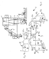
- a blown film line 1 consists of at least one extruder 2 for melting and extruding the polymer granules, which are extruded into a film tube in a tool unit 3 and then inflated to a tubular film 4.
- a number of extruders and a suitable adapter system for the tool unit 3 or a special spray nozzle are required, depending on the number of different polymers.
- 1a shows, the tubular film 4 consists of a tubular body, the inner wall of which is designated I and the outer wall of which is A. This tubular film 4, as shown in FIG.
- the further treatment also includes the slitting of the tubular film 4 by means of a separating device, not shown, which slits the folded tubular film in the longitudinal direction at the two opposite kink edges into two flat film webs, while it continuously runs past the separating device.
- the flat film webs with the inner sides I remain on top of each other so that they have to be separated later.
- the superimposed film webs 8 are then fed to the turning device 9, which separates the film webs and aligns them in the same lateral position in such a way that the two flat film webs point in the same direction with their inner sides I or with their outer sides A.
- the turning device 9 for the vertically incoming film webs 8 has four rotatably mounted deflection devices 10a, b, c, d, the combination of which brings about the turning of both film webs according to the invention.
- the first deflection device 10a is connected upstream of the turning device 9 and deflects the two film webs 8 arriving vertically with the identical running directions 16 by 90 degrees into the horizontal entry running direction 17.
- the first deflection device 10a is inclined counterclockwise by 45 degrees to the film running direction 16, which is vertical here, and is wrapped around on a partial circumference by two film webs lying on top of one another.
- the two film webs could alternatively be deflected as a film tube in the unslit state in the manner shown.
- the film tube is slit open to "flat films" immediately before the next deflection device 10b.
- the next deflection device 10b in the form of a rotatably mounted roller or roller is defined as the first deflection device 10b of the turning device.
- the one of the two film webs 8, which is now at the rear, is reversed by 180 degrees on the first deflection device 10b of the turning device 9.
- the film webs lying one on top of the other are separated from one another.
- the front of the two film webs is continued with the previous direction of movement 18r, while the rear of the two films continues in the reverse direction of movement 18 l.
- this film web is referred to from here as deflected flat film 11.
- Both running directions 18r, 18l are directed in opposite directions and point away from each other.
- a second deflection device 10c, 10d is then provided, which lies in relation to the running direction of the associated film such that each film web is deflected from the horizontal running direction into the vertical starting running direction 19r, 19l.
- the deflection device 10c is inclined 45 degrees counterclockwise and the deflection device 10d 45 degrees clockwise at an angle to the vertical, and both deflection devices are wrapped around by the film webs on a partial circumference.
- the outside Ar of the right-hand film web R and the outside A1 of the left-hand film web L are on the back or on the front of the two superimposed films 8 before they reach the first deflection device 10b of the turning device.
- both outer sides Ar and Al are located on the front of the separately moving films R and L, and are reversed at the deflection devices 10c, 10d and turned on the invisible rear side.
- the former inner sides Il, Ir reach the now visible front sides of the two foil webs.
- both film webs assume a side position in which they are with their outer sides or inner sides point uniformly in the same direction.
- the directional film webs are then fed to a right or left winding device 13r or 13 l, which drive the film roll 14r or 14 l in the same directions of rotation 15, so that the outer sides Ar, Al of all windings 14 in this exemplary embodiment of the invention Point the film tube 4 uniformly outwards.
- FIG. 2 Another embodiment of the invention is shown in FIG. 2.
- the description of FIG. 1 applies in full to this representation.
- the difference lies in the fact that on the first deflection device 10b of the turning device 9, the front of the two film webs is reversed. This results in the fact that the two films are now visible with their outer sides A-1, A-r in front of the winding device, and accordingly, while maintaining the winding direction 15, the former outer sides of the film tube 4 point inwards for all the windings 14.
- FIG. 3 Another embodiment of the invention is shown in FIG. 3.
- the rear of the two film webs L is reversed by 180 degrees as an example. As in FIG. 1, this is achieved by a deflecting device 10b with its axis of rotation perpendicular to the input running direction 17.
- the deflected film web is then passed over a second deflection device 10c, which rotates 45 degrees counterclockwise from the vertical upward direction of the rear film web L is rotated.
- the rear film is deflected into the horizontal and is fed with this running direction to a third deflection device 10e, which is rotated 45 degrees in the opposite direction of rotation, that is to say clockwise from the vertical.
- the third deflection device 10e deflects the incoming film web L in the vertically downward direction 19L, and both film webs R, L are fed parallel to each other and with their outer sides Ar, Al pointing in the same direction to their co-rotating (rotation direction 15) winding devices 13 .
- flat film when used in the claims or in the description of this invention, stands for a flat film web of a tubular film produced by the film blowing process or a split half-tube, which has a biaxial orientation due to its manufacturing process.
- flat film is usually understood to mean a film web produced by the wide-injection or film casting process and possibly mono- or biaxially stretched.
Landscapes
- Engineering & Computer Science (AREA)
- Mechanical Engineering (AREA)
- Shaping By String And By Release Of Stress In Plastics And The Like (AREA)
Claims (13)
- Procédé de fabrication de feuilles planes par fendage longitudinal et séparation d'une feuille (4) soufflée mise à plat, laquelle feuille est amenée à des dispositifs (13) d'enroulement et est enroulée dans ceux-ci de manière telle que, pour chaque rouleau (14), la face intérieure (I) ou la face extérieure (A) de la feuille (4) soufflée mise à plat soit orientée de manière uniforme dans la même direction, les deux bandes (12 l, 12 r) de feuille plane étant séparées l'une de l'autre, à partir de leur direction commune de marche, par déviation de l'une des deux bandes (12 l, 12 r) en aval du point où la feuille (4) soufflée mise à plat est séparée en deux bandes de feuille (12 l, 12 r) planes, vu dans la direction (16) de marche de la feuille, caractérisé par le fait que, vu dans la direction (16) de marche de la feuille, en aval du point où les deux bandes (12 l, 12 r) planes de feuille sont séparées l'une de l'autre, on dévie l'une des bandes (12 l) de feuille dans la même direction (19) de marche en la décalant parallèlement à la direction de marche de l'autre bande (12 r) et par le fait que l'on amène les deux bandes de feuille (12 l, 12 r) aux deux dispositifs (13) d'enroulement qui sont disposés dans cette direction (19), sont décalés parallèlement et sont entraînés dans le même sens de rotation (15).
- Procédé selon la revendication 1, caractérisé par le fait que, partant d'une direction d'entrée (17) commune, on amène les deux bandes (12 l, 12 r) de feuille plane, après leur séparation et après le changement de direction de marche de l'une des deux bandes dans une direction de sortie (19) verticale dans les dispositifs (13) d'enroulement.
- Procédé selon la revendication 2, caractérisé par le fait que la direction d'entrée (17) est horizontale et par le fait qu'après un changement de direction de marche à 180 degrés de l'une (11) des bandes de feuille on dévie la direction de marche des deux bandes de feuille à 90 degrés dans la direction (19) de sortie verticale et ce faisant on fait tourner les deux bandes de feuille de 180 degrés autour de leur axe longitudinal de manière telle que lesdites deux bandes (12 l, 12 r) soient enroulées avec la même face (A, I) tournée vers l'extérieur pour former un rouleau (14 l, 14 r) de feuille.
- Procédé selon la revendication 3, caractérisé par le fait que l'on dévie simultanément à 90 degrés les bandes de feuille à partir de la direction (16) verticale de marche pour les amener dans la direction (17) horizontale d'entrée.
- Procédé selon la revendication 2, caractérisé par le fait que la direction (17) d'entrée est verticale et par le fait que l'on dévie tout d'abord à 90 degrés la bande de feuille (L) déviée pour l'amener dans une direction de marche horizontale à la suite de quoi, à partir de cette direction, on la dévie à 90 degrés pour l'amener dans la direction de sortie (19) verticale.
- Installation (1) de production de feuille soufflée pour une feuille (4) soufflée mise à plat qui est fendue longitudinalement au moyen d'un dispositif de séparation pour former des bandes de feuille (12 l, 12 r) planes, les bandes de feuille planes séparées étant amenées chacune à un dispositif (13) d'enroulement et enroulées sur ceux-ci de manière telle que dans chaque rouleau (14) la face intérieure (I) ou la face extérieure (A) de la feuille (4) soufflée soit orientée de manière uniforme dans la même direction, caractérisée par le fait qu'il est prévu un dispositif de retournement (9) en aval du dispositif de séparation assurant la division de la feuille (4) soufflée mise à plat en deux bandes (12 l, 12 r) de feuille plane et par le fait que les deux bandes (12 l, 12 r) de feuille sont introduites dans le dispositif de retournement (9) et retournées autour de leur axe longitudinal de manière telle que, partant de leur direction de marche commune, les deux bandes (12 l, 12 r) sont séparées l'une de l'autre par déviation de l'une (12 l) d'entre elles, que ladite bande (12 l) de feuille est ensuite déviée de nouveau dans la même direction de marche (19) en étant décalée parallèlement à l'autre bande (12 r) de feuille et que les deux bandes (12 l, 12 r) sont amenées aux deux dispositifs (13) d'enroulement qui sont disposés dans cette direction (19), sont décalés parallèlement et sont entraînés dans le même sens de rotation (15).
- Installation (1) de production de feuille soufflée selon la revendication 6, caractérisée par le fait que les bandes de feuille arrivent dans la direction horizontale (17) d'entrée dans le dispositif de retournement (9) dans lequel un premier dispositif (10 b) de déviation est disposé perpendiculairement à la direction de marche (17) des feuilles aux fins d'inverser la direction de marche de l'une des deux bandes et par le fait qu'il est prévu à la suite de celui-ci, pour les deux bandes de feuille, un deuxième dispositif de déviation (10 c, 10 d) qui, par rapport à la direction de marche des bandes de feuille concernées, est disposé de telle sorte que lesdites bandes de feuille soient déviées dans une direction verticale de marche en direction des dispositif d'enroulement (13) disposés côté à côté et décalés parallèlement.
- Installation (1) de production de feuille soufflée selon la revendication 6, caractérisée par le fait que les bandes de feuille soufflée circulent dans la direction verticale vers la bas dans le dispositif de retournement (9) dans lequel un premier dispositif de déviation (10 b) aux fins d'inverser la direction de marche de l'une des deux bandes de feuille est disposé perpendiculairement à la direction de marche (17), par le fait qu'il est prévu, pour la bande de feuille (L) déviée, un deuxième dispositif de déviation (10 c) incliné qui dévie horizontalement la direction de marche de la bande et par le fait qu'il est prévu un troisième dispositif de déviation (10 e) incliné au moyen duquel la bande est amenée dans la direction (19) verticale de marche.
- Installation (1) de production de feuille soufflée selon la revendication 7, caractérisée par le fait que les bandes de feuille sont amenées dans la direction verticale (16) de marche dans le dispositif de retournement (9) et que les bandes de feuille sont déviées dans la direction d'entrée (17) horizontale par un dispositif de déviation (10 a) disposé à 45 degrés par rapport à la direction (16) de marche des bandes.
- Installation (1) de production de feuille soufflée selon l'une des revendications 6 à 9, caractérisée par le fait que les bandes de feuille dont les faces sont orientées de la même manière circulent parallèlement et sensiblement dans le même plan en direction de leur dispositif (13) d'enroulement respectif.
- Installation (1) de production de feuille soufflée selon l'une des revendications 7 à 10, caractérisée par le fait que les dispositifs de déviation (10 - 10 e) sont disposés dans un plan de manière telle que les bandes de feuilles soient parallèles entre elles dans le dispositif de retournement (9).
- Installation (1) de production de feuille soufflée selon l'une des revendications 6 à 10, caractérisée par le fait que la feuille (4) soufflée est séparée en deux bandes de feuille planes de même largeur.
- Installation (1) de production de feuille soufflée selon l'une au moins des revendications 6 à 12, caractérisée par le fait que les dispositifs d'enroulement (13) sont disposés côte à côte et que les arbres mutuellement alignés ou mutuellement parallèles de deux dispositifs d'enroulement (13) consécutifs sont entraînés dans le même sens de rotation (15) et avec la même vitesse de rotation.
Applications Claiming Priority (2)
| Application Number | Priority Date | Filing Date | Title |
|---|---|---|---|
| DE4123083 | 1991-07-12 | ||
| DE4123083 | 1991-07-12 |
Publications (2)
| Publication Number | Publication Date |
|---|---|
| EP0522536A1 EP0522536A1 (fr) | 1993-01-13 |
| EP0522536B1 true EP0522536B1 (fr) | 1995-10-11 |
Family
ID=6435980
Family Applications (1)
| Application Number | Title | Priority Date | Filing Date |
|---|---|---|---|
| EP92111603A Expired - Lifetime EP0522536B1 (fr) | 1991-07-12 | 1992-07-08 | Installation d'extrusion-soufflage |
Country Status (2)
| Country | Link |
|---|---|
| EP (1) | EP0522536B1 (fr) |
| DE (1) | DE59203959D1 (fr) |
Families Citing this family (2)
| Publication number | Priority date | Publication date | Assignee | Title |
|---|---|---|---|---|
| DE10342620B4 (de) * | 2003-09-12 | 2010-09-30 | Windmöller & Hölscher Kg | Folienwendestation |
| DE102015012653A1 (de) * | 2015-10-01 | 2017-04-06 | Reifenhäuser GmbH & Co Maschinenfabrik | Wickelstation für eine Folienextrusionsanlage, Folienextrusionsanlage und Verfahren zum Betreiben einer Folienextrusionsanlage |
Family Cites Families (6)
| Publication number | Priority date | Publication date | Assignee | Title |
|---|---|---|---|---|
| US2995990A (en) * | 1956-04-18 | 1961-08-15 | Union Carbide Corp | Apparatus for the production of gusseted tubing |
| US3231651A (en) * | 1961-01-03 | 1966-01-25 | Dow Chemical Co | Plastic film windup apparatus |
| DE1948935C3 (de) * | 1969-09-27 | 1982-02-04 | General Engineering Co.(Radcliffe)Ltd., Manchester | Flachlege- und Abzugsvorrichtung für eine im Blasverfarhen hergestellte Kunststoff-Schlauchfolienbahn |
| DE3100520A1 (de) * | 1979-07-14 | 1982-08-12 | Mannesmann Demag Kunstofftechnik Zweigniederlassung der Mannesmann Demag AG, 8500 Nürnberg | Flachlege- und abzugsvorrichtung fuer im blasverfahren hergestellte kunststoff-schlauchfolien |
| DE8707626U1 (de) * | 1987-05-27 | 1987-08-13 | Alpine Ag, 8900 Augsburg | Abzugsvorrichtung für Schlauchfolien |
| ES2041797T3 (es) * | 1988-06-22 | 1993-12-01 | Remver S.A. (A Corp. Of Panama) | Procedimiento y aparato para un conjunto de rodillos de presion oscilante utilizado en la extrusion por soplado de peliculas. |
-
1992
- 1992-07-08 EP EP92111603A patent/EP0522536B1/fr not_active Expired - Lifetime
- 1992-07-08 DE DE59203959T patent/DE59203959D1/de not_active Expired - Fee Related
Also Published As
| Publication number | Publication date |
|---|---|
| EP0522536A1 (fr) | 1993-01-13 |
| DE59203959D1 (de) | 1995-11-16 |
Similar Documents
| Publication | Publication Date | Title |
|---|---|---|
| DE68925424T2 (de) | Vorrichtung und verfahren zum helicoidalen schneiden von flexiblen schlauchförmigen warenbahnen aus polymermaterial | |
| DD263261A5 (de) | Verfahren zur herstellung einer ersten fahrzeugradialreifenvorstufe | |
| EP0408996B1 (fr) | Dispositif de tirage de films tubulaires en matière plastique | |
| DE3508626C1 (de) | Flachlege- und Abzugsvorrichtung fuer eine aus Kunststoff im Blasverfahren hergestellte Schlauchfolienbahn | |
| EP0005776A1 (fr) | Dispositif de fabrication de sacs en matière plastique munis de baguettes de fermeture à pression | |
| EP1999051B1 (fr) | Dispositifs et procédé d'acheminement une bande de matière à une unité d'impression d'une rotative d'imprimerie | |
| EP0145029A2 (fr) | Dispositif d'enroulement ou de déroulement à plusieurs arbres en cascade | |
| DE69604967T2 (de) | Vorrichtung zum vorbereitenden Zusammensetzen von Reifenteilen | |
| EP0999991B1 (fr) | Procede de bobinage, dispositif de separation de bande et bobineuse de bande | |
| DE1900614C3 (de) | Flachlege- und Abzugvorrichtung für im Blasverfahren hergestellte Kunststoffschlauchfolienbahnen | |
| DE69713137T2 (de) | Wickelmaschine für ein flaches endloses element zur bildung von bahnwickeln | |
| EP0522536B1 (fr) | Installation d'extrusion-soufflage | |
| DE1928188A1 (de) | Flachlege- und Abzugsvorrichtung fuer im Blasverfahren hergestellte Kunststoffschlauchfolien | |
| EP0676351A2 (fr) | Dispositif de transport pour bandes plates en feuille de matière plastique | |
| DE3324978C2 (de) | Flachlege- und Abzugsvorrichtung für eine im Blasverfahren von einem ortsfest angeordneten Folienblaskopf hergestellte Kunststoffschlauchfolienbahn | |
| EP0271800A1 (fr) | Convoyeur, en particulier pour des imprimés pliés | |
| DE3888975T2 (de) | Verfahren und vorrichtung zum herstellen von verstärkter lage. | |
| WO1991010553A1 (fr) | Procede de fabrication d'une feuille de plastique en thermoplastique | |
| DE69403253T2 (de) | Verfahren zum Aufwickeln von kernlosen Rollen | |
| EP1597054B1 (fr) | Tuyau, dispositif et procede pour le produire | |
| DE102004017952B4 (de) | Vorrichtung zum Transport eines Folienschlauches | |
| EP3880592B1 (fr) | Procédé et dispositif d'enroulement successif d'un film continu ainsi que rouleau de film | |
| EP0886620B1 (fr) | Dispositif d'enroulement continu de bandes de papier coupees longitudinalement avec changement automatique des rouleaux a vitesse de la machine | |
| EP0673750A1 (fr) | Dispositif pour la mise à plat d'un film tubulaire soufflé en matière thermoplastique | |
| DE29621374U1 (de) | Abzugsvorrichtung für bahnförmiges Kunststoff-Folienmaterial |
Legal Events
| Date | Code | Title | Description |
|---|---|---|---|
| PUAI | Public reference made under article 153(3) epc to a published international application that has entered the european phase |
Free format text: ORIGINAL CODE: 0009012 |
|
| AK | Designated contracting states |
Kind code of ref document: A1 Designated state(s): CH DE ES FR GB IT LI |
|
| 17P | Request for examination filed |
Effective date: 19921214 |
|
| 17Q | First examination report despatched |
Effective date: 19940617 |
|
| ITF | It: translation for a ep patent filed | ||
| GRAA | (expected) grant |
Free format text: ORIGINAL CODE: 0009210 |
|
| AK | Designated contracting states |
Kind code of ref document: B1 Designated state(s): CH DE ES FR GB IT LI |
|
| PG25 | Lapsed in a contracting state [announced via postgrant information from national office to epo] |
Ref country code: ES Free format text: THE PATENT HAS BEEN ANNULLED BY A DECISION OF A NATIONAL AUTHORITY Effective date: 19951011 |
|
| ET | Fr: translation filed | ||
| GBT | Gb: translation of ep patent filed (gb section 77(6)(a)/1977) |
Effective date: 19951010 |
|
| REF | Corresponds to: |
Ref document number: 59203959 Country of ref document: DE Date of ref document: 19951116 |
|
| PLBE | No opposition filed within time limit |
Free format text: ORIGINAL CODE: 0009261 |
|
| STAA | Information on the status of an ep patent application or granted ep patent |
Free format text: STATUS: NO OPPOSITION FILED WITHIN TIME LIMIT |
|
| 26N | No opposition filed | ||
| PGFP | Annual fee paid to national office [announced via postgrant information from national office to epo] |
Ref country code: GB Payment date: 19970707 Year of fee payment: 6 |
|
| PGFP | Annual fee paid to national office [announced via postgrant information from national office to epo] |
Ref country code: FR Payment date: 19970718 Year of fee payment: 6 |
|
| PGFP | Annual fee paid to national office [announced via postgrant information from national office to epo] |
Ref country code: CH Payment date: 19970804 Year of fee payment: 6 |
|
| REG | Reference to a national code |
Ref country code: CH Ref legal event code: NV Representative=s name: BARMAG GMBH ENGINEERING & MANUFACTURING |
|
| PG25 | Lapsed in a contracting state [announced via postgrant information from national office to epo] |
Ref country code: GB Free format text: LAPSE BECAUSE OF NON-PAYMENT OF DUE FEES Effective date: 19980708 |
|
| PG25 | Lapsed in a contracting state [announced via postgrant information from national office to epo] |
Ref country code: LI Free format text: LAPSE BECAUSE OF NON-PAYMENT OF DUE FEES Effective date: 19980731 Ref country code: CH Free format text: LAPSE BECAUSE OF NON-PAYMENT OF DUE FEES Effective date: 19980731 |
|
| GBPC | Gb: european patent ceased through non-payment of renewal fee |
Effective date: 19980708 |
|
| REG | Reference to a national code |
Ref country code: CH Ref legal event code: PL |
|
| PG25 | Lapsed in a contracting state [announced via postgrant information from national office to epo] |
Ref country code: FR Free format text: LAPSE BECAUSE OF NON-PAYMENT OF DUE FEES Effective date: 19990331 |
|
| REG | Reference to a national code |
Ref country code: FR Ref legal event code: ST |
|
| PGFP | Annual fee paid to national office [announced via postgrant information from national office to epo] |
Ref country code: DE Payment date: 20000217 Year of fee payment: 8 |
|
| PG25 | Lapsed in a contracting state [announced via postgrant information from national office to epo] |
Ref country code: DE Free format text: LAPSE BECAUSE OF NON-PAYMENT OF DUE FEES Effective date: 20010501 |
|
| PG25 | Lapsed in a contracting state [announced via postgrant information from national office to epo] |
Ref country code: IT Free format text: LAPSE BECAUSE OF NON-PAYMENT OF DUE FEES;WARNING: LAPSES OF ITALIAN PATENTS WITH EFFECTIVE DATE BEFORE 2007 MAY HAVE OCCURRED AT ANY TIME BEFORE 2007. THE CORRECT EFFECTIVE DATE MAY BE DIFFERENT FROM THE ONE RECORDED. Effective date: 20050708 |