EP0522745A1 - Dispositif de soupape annulaire pour une pompe de fluide à mouvement alternatif - Google Patents
Dispositif de soupape annulaire pour une pompe de fluide à mouvement alternatif Download PDFInfo
- Publication number
- EP0522745A1 EP0522745A1 EP19920305789 EP92305789A EP0522745A1 EP 0522745 A1 EP0522745 A1 EP 0522745A1 EP 19920305789 EP19920305789 EP 19920305789 EP 92305789 A EP92305789 A EP 92305789A EP 0522745 A1 EP0522745 A1 EP 0522745A1
- Authority
- EP
- European Patent Office
- Prior art keywords
- valve
- ring valve
- ring
- cylinder head
- retainer
- Prior art date
- Legal status (The legal status is an assumption and is not a legal conclusion. Google has not performed a legal analysis and makes no representation as to the accuracy of the status listed.)
- Granted
Links
- 239000012530 fluid Substances 0.000 title claims abstract description 34
- 230000006835 compression Effects 0.000 claims description 12
- 238000007906 compression Methods 0.000 claims description 12
- 230000002093 peripheral effect Effects 0.000 claims description 10
- 238000000034 method Methods 0.000 claims 4
- 230000004048 modification Effects 0.000 description 9
- 238000012986 modification Methods 0.000 description 9
- 238000013459 approach Methods 0.000 description 3
- 238000010276 construction Methods 0.000 description 3
- 230000000694 effects Effects 0.000 description 3
- 238000009434 installation Methods 0.000 description 3
- 238000003754 machining Methods 0.000 description 3
- 239000000463 material Substances 0.000 description 3
- 238000007789 sealing Methods 0.000 description 3
- 238000009987 spinning Methods 0.000 description 3
- 230000009471 action Effects 0.000 description 2
- 230000008859 change Effects 0.000 description 2
- 238000004891 communication Methods 0.000 description 2
- 238000006073 displacement reaction Methods 0.000 description 2
- 230000006872 improvement Effects 0.000 description 2
- 229910000831 Steel Inorganic materials 0.000 description 1
- 230000004075 alteration Effects 0.000 description 1
- 230000007423 decrease Effects 0.000 description 1
- 230000003247 decreasing effect Effects 0.000 description 1
- 230000001419 dependent effect Effects 0.000 description 1
- 238000009826 distribution Methods 0.000 description 1
- 238000004519 manufacturing process Methods 0.000 description 1
- 230000001737 promoting effect Effects 0.000 description 1
- 238000005086 pumping Methods 0.000 description 1
- 230000000284 resting effect Effects 0.000 description 1
- 239000010959 steel Substances 0.000 description 1
Images


Classifications
-
- F—MECHANICAL ENGINEERING; LIGHTING; HEATING; WEAPONS; BLASTING
- F04—POSITIVE - DISPLACEMENT MACHINES FOR LIQUIDS; PUMPS FOR LIQUIDS OR ELASTIC FLUIDS
- F04B—POSITIVE-DISPLACEMENT MACHINES FOR LIQUIDS; PUMPS
- F04B39/00—Component parts, details, or accessories, of pumps or pumping systems specially adapted for elastic fluids, not otherwise provided for in, or of interest apart from, groups F04B25/00 - F04B37/00
- F04B39/10—Adaptations or arrangements of distribution members
- F04B39/102—Adaptations or arrangements of distribution members the members being disc valves
- F04B39/1033—Adaptations or arrangements of distribution members the members being disc valves annular disc valves
-
- F—MECHANICAL ENGINEERING; LIGHTING; HEATING; WEAPONS; BLASTING
- F04—POSITIVE - DISPLACEMENT MACHINES FOR LIQUIDS; PUMPS FOR LIQUIDS OR ELASTIC FLUIDS
- F04B—POSITIVE-DISPLACEMENT MACHINES FOR LIQUIDS; PUMPS
- F04B39/00—Component parts, details, or accessories, of pumps or pumping systems specially adapted for elastic fluids, not otherwise provided for in, or of interest apart from, groups F04B25/00 - F04B37/00
- F04B39/10—Adaptations or arrangements of distribution members
- F04B39/1073—Adaptations or arrangements of distribution members the members being reed valves
- F04B39/1086—Adaptations or arrangements of distribution members the members being reed valves flat annular reed valves
-
- F—MECHANICAL ENGINEERING; LIGHTING; HEATING; WEAPONS; BLASTING
- F04—POSITIVE - DISPLACEMENT MACHINES FOR LIQUIDS; PUMPS FOR LIQUIDS OR ELASTIC FLUIDS
- F04B—POSITIVE-DISPLACEMENT MACHINES FOR LIQUIDS; PUMPS
- F04B53/00—Component parts, details or accessories not provided for in, or of interest apart from, groups F04B1/00 - F04B23/00 or F04B39/00 - F04B47/00
- F04B53/10—Valves; Arrangement of valves
- F04B53/1075—Valves; Arrangement of valves the valve being a flexible annular ring
-
- Y—GENERAL TAGGING OF NEW TECHNOLOGICAL DEVELOPMENTS; GENERAL TAGGING OF CROSS-SECTIONAL TECHNOLOGIES SPANNING OVER SEVERAL SECTIONS OF THE IPC; TECHNICAL SUBJECTS COVERED BY FORMER USPC CROSS-REFERENCE ART COLLECTIONS [XRACs] AND DIGESTS
- Y10—TECHNICAL SUBJECTS COVERED BY FORMER USPC
- Y10T—TECHNICAL SUBJECTS COVERED BY FORMER US CLASSIFICATION
- Y10T137/00—Fluid handling
- Y10T137/7722—Line condition change responsive valves
- Y10T137/7837—Direct response valves [i.e., check valve type]
- Y10T137/7879—Resilient material valve
- Y10T137/7888—With valve member flexing about securement
Definitions
- Ring type valves per se are well known in the art, and have a wide acceptance in use for air compressors and pumps. Basically, these ring type valves are opened and closed by pressure differential on opposite sides of the ring valve. It is also heretofore known to include biasing of spring devices along with such ring valves in order to accurately control valve movement upon a pressure differential which is above the spring force of the spring selected in each case. In this way, the valve is opened or closed only upon reaching a pre-determined pressure differential dependent on the spring properties of the spring chosen and the mass of the valve, wherein the valve action can be predicted.
- the said U.S. Letters Patent Application No. 07/728,225 (issued June 11, 1991 as U.S. Patent No.
- a solution to some of the problems discussed above is achieved in one embodiment of the present invention by providing a ring valve assembly which essentially no longer has external spring biasing means, but could be said to have what can be referred to as "internal” spring biasing means, i.e., a bias that depends on the property of the ring valve itself.
- This is achieved by physically constraining the inner or outer peripheral edge of the ring valve between opposing faces, with a small clearance, if desired, and having the ring valve deform during operation into the shape of a cone.
- a retainer with a tapered surface is used as a back-up to the ring valve deflection.
- Ring valves having their peripheral edges restrained are known in the field of air compressors, such as issued United States patent nos. 2,728,351 and 3,112,064. They are also known from Austrian patent no. A2145/69-1 and Austrian patent application no. 871336.
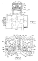
- Figure 1 is an elevational view, partially cut away, of a ring valve type air compressor embodying the present invention.
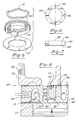
- Figure 3 is an elongated view of a cylinder head of a ring valve type air compressor similar to that shown in Figure 1 but leaving an unloader device mounted on the intake thereof, said unloader device being shown in section.
- Figure 7 is an elevational view of the valve retainer shown in Figure 6 taken along line 7-7 of Figure 6.
- Figure 8 is a further enlarged view of the cylinder head shown in Figure 2 showing the operation of the ring valves of the present invention at the beginning of the intake stroke of a fluid pump embodying the present invention.
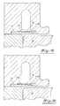
- Figure 9 is a view of the fluid pump shown in Figure 8 at the point where the fluid pump of the present invention has just started its compression stroke.
- Figure 10 is a view of the fluid pump shown in Figures 8 and 9 when said pump is near the top of its compression stroke, the intake ring valve has closed, and the exhaust ring valve has opened.
- FIG 11 shows a further modification of the valve retainer shown in Figure 5.
- Figure 12 is an enlarged view of the modified valve retainer shown in Figure 11.
- Figure 13 is a greatly enlarged view of a portion of the valve body shown in Figures 8-10, showing the operating clearances of the intake ring valve and exhaust ring valve.
- Figure 15 is a view similar in large part to Figure 14 but showing the piston further along on its intake stroke and illustrating the stages of deflection of the intake ring valve.
- Figure 16 is a graph of displacement versus pressure or force required to displace the ring valves.
- Figure 18 is the enlarged section view of Figure 17 with the ring valve and retainer assembled and the piston illustrated.
- Figure 19 is the enlarged section view of Figure 18 after the ring valve undergoes its first stage of vertical movement.
- Figure 20 is the enlarged section view of Figure 19 after the ring valve deflects into a frustoconical form against the retainer.
- the cylinder head Closing the top of the piston cylinder 21 is the cylinder head, generally designated by the numeral 25 which, in a typical installation, consists of the compressor valve body 26, which has sealing surfaces (valve seat means) for the ring valves hereinafter described, the compressor head 27, and the cover plate 28.
- a cover plate gasket 29 is provided to seal the cover plate 28 to the compressor head 27.
- a head gasket 30 provides for the sealing connection of the compressor head 27 to the compressor valve body 26, while the valve body gasket 31 provides for a sealing connection of the compressor valve body 26 to the top of the piston cylinder 21.
- the cover plate 28 is fastened to the compressor valve body 26 by means of the bolt 33 first being passed through the washer 34 and then through the hole 35 provided in the cover plate 28. It is then passed through the second hole 36 provided centrally of the compressor head 27 and into the threaded opening 37 provided in the center post section 38 of the compressor valve body 26. When the bolt 33 is tightened, both the cover plate 28 and the compressor head 27 are sealingly fastened to the compressor valve body 26. A recess 32 is provided in the cover plate 28.
- the compressor valve body 26 is in turn fastened to the top of the piston cylinder 21 by the head bolts 39 which, for ease of illustration, are only shown in Figure 1.
- the piston cylinder 21, the piston 22 and the cylinder head 25 define a fluid chamber, more particularly a gas compression chamber 40, the volume of which is varied by movement of the piston 22.
- the outer circular ridge 49 overlaps the piston cylinder 21 and the valve body gasket 31 and thus the outer peripheral edge of ring valve 50 is clamped in place or constrained between a first pair of opposing annular surfaces formed by the valve body gasket 31 and the compressor valve body 26.
- there is a clearance between the ring valve 50 and the outer circular ridge 49 which allows the ring valve 50 to pivot slightly before beginning to deform. This will be explained in more detail in connection with Figures 13-16.
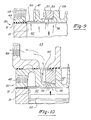
- a second inner circular ridge 55, and a second outer circular ridge 56 which together serve as a second valve seat means for the second ring valve 57.
- the dimensions of the second inner circular ridge 55 and the inside dimension of the second ring valve 57 are such that the second ring valve may slip over an annular post portion 58 of the compressor valve body 26 and come to rest on said second inner circular ridge.
- the second ring valve is thereby constrained by a second pair of opposing annular surfaces formed by valve retainer 59 and the second inner ridge 55.
- the second ring valve 57 it is the inner peripheral edge of the ring valve which is held in place by the valve retainer 59 which is mounted over the top of the second ring valve 57 on the annular post portion 58. There may be provided a slight clearance between the top of the valve retainer 59 and the compressor valve body 26 to allow for a slight movement under certain operating conditions when resonance might otherwise be a problem.
- An exhaust 62 is provided in the compressor head 27 which is in communication with an exhaust gallery 63 which is in communication with the circular passageway 64 formed above the second ring valve 57 between the wall of the upper surface of the compressor valve body 26 and the valve retainer 59.
- Figure 8 shows the compressor 20 with the piston 22 at the top of the stroke just starting the intake stroke of the compressor.
- the downward stroke of the piston 22 causes enough suction to cause the ring valve 50 to deform downwardly into a cone shape, and provide an opening between the ring valve 50 and the inner circular ridge 47 through which air or fluid can pass. This allows air entering the intake 45 to pass by the ring valve 50 into the compression chamber 40.
- the suction against the second ring valve 57 just forces it additionally against the second inner circular ridge 55 and the second outer circular ridge 56 and keeps the second ring valve or exhaust valve 57 sealed.
- the compression chamber 40 is completely filled with air.
- the piston 22 (not shown in this view) is just starting its upward stroke. This causes sufficient displacement of the air in the compression chamber 40 to cause the intake valve 50 to move upwardly and seat against the inner circular ridge 47, preventing air from escaping back out the intake 45. Air continues to compress until, as shown in Figure 10, the air reaches a sufficient pressure to cause the exhaust valve 57 to open.
- the dimensions of the first and second ring valves, as well as the materials which they are made from, will be carefully chosen depending upon the application to ensure the proper relationship between the opening of the intake or ring valve 50 and the opening of the second ring valve or exhaust valve 57.
- Figures 5 and 8-10 show the preferred embodiment of the ring valve retainer 59
- Figures 6 and 7 show a modification thereon
- Figures 11 and 12 taken together show a further modification of the ring valve retainer 59.
- valve retainer 59 shown in Figure 8, has an annularly shaped flat portion 68 substantially identical in radial dimension to the second inner circular ridge 55 to retain the inner peripheral surface of the ring valve 57 in the manner hereinbefore described.
- the balance of the lower surface of the ring valve retainer 59 is a tapered surface 69 allowing the ring valve to deform in the shape of a cone upon the application of air pressure.
- valve retainer 59 has a recess 60 identical to that in all the other versions of the valve retainer. However, instead of having a completely tapered surface, it has a radially extending flat 65 provided on the lower surface through a diameter thereof, with the remainder of the lower surface 66 then being more or less V-shaped, as viewed in Figure 7, so instead of deforming into a cone upon the application of air pressure thereto, the ring valve 57 will deform into a "V".
- the modification shown in Figures 11 and 12 instead of having the flat surface 65 together with a "V" shaped surface 66, has an inner, annular, flat surface 70 and an outer annular surface 71.
- the difference in dimension between the inner, annularly shaped, flat 70 and the outer annular surface 71 is such that the ring valve 57 still forms into a cone shape upon the application of pressure thereto, but in this case, the recess 72 allows for pressure relief.
- the unloading valve 75 is constructed of an air intake manifold 78 having an intake opening 78A and a central opening 78B. Air passes through the inlet 76, the central opening 78B and the intake opening 78A into the intake of the compressor when the top hat 83 is open.
- a unloader valve body 80 mounted to the intake manifold 78 is a unloader valve body 80 sealingly connected to the intake manifold 78 by the O-ring seal 90.
- a pressurized air inlet 77 communicating with central bore 81. Sealingly mounted in the bore 81 by the rectangular seal 82 is the top hat 83.
- the intake valve 50 is not held tightly between the first pair of opposing annular surfaces formed by the outer circular ridge 49 and the valve body gasket 31, but instead, is provided with a small clearance indicated by C2.
- Figure 13 shows the piston 22 approaching the top of the compression stroke when the exhaust valve 57 is pressed against the tapered surface 69 of the valve retainer 59. The intake valve 50 is pressed upwardly against the inner circular ridge 47 and the outer circular ridge 49. In this position, there is the clearance C2 between the bottom of the intake valve 50 and the top of the valve body gasket 31. In a typical installation, the intake valve will be .015" thick and the clearance C2 will be .003".
- the exhaust valve 57 is shown in its lower most position, resting on the second inner circular ridge 55 and the second outer circular ridge 56 a distance X from the bottom of the compressor valve body 26.
- the thicknesses of the intake and exhaust valve, the stiffness thereof, and the dimensions of the valves themselves, as well as the various dimensions of the compressor or fluid pump can vary widely and still be within the scope of the present invention.
- the material of which the ring valves are made can vary widely and still be within the scope of the present invention.
- the ring valves are made of steel, and the intake valve rotates (has its fulcrum) at edge A or a rubber covered valve body gasket.
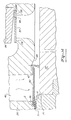
- FIGS. 17 and 18 another intake valve embodiment of the present invention is illustrated.
- the embodiments of FIGS. 13 and FIG. 17 - 18 are similar in a number of respects and many of the same components, surfaces and features appear in FIGS. 17 - 18 as they appear in FIG. 13.
- the primary difference between the FIG. 13 embodiment and the embodiment of FIGS. 17 - 18 resides in the removal of valve body gasket 31 and the addition of an intake valve retainer.
- the compressor valve body has been modified to the illustrated compressor valve body 101 of FIG. 17.
- first circular relief channel 102 and a corresponding annular ring recess 103 which extends radially inwardly to surface 104 of relief area 48.
- the ring valve relief area 105 is disposed concentric with and immediately above recess 103.
- Area 105 includes a circular relief channel 106 and an annular ring recess 107.
- Recess 107 extends radially inwardly to surface 104 of relief area 48.
- the base of gallery 46 (FIG. 13) has been expanded in FIG. 17 by the addition of conical surface 108 which in combination with recess 107 helps to define gallery 109.
- the bottom face of gallery 109 is further defined in part by inner circular ridge 110 and outer circular ridge 111.
- Retainer 115 has an annular ring shape and an approximate four degree downward taper from fulcrum edge 115a along surface 115b as the retainer extends radially inwardly. This four degree taper is defined by angle 116. Retainer 115 is sized so as to assemble with eithr a line-to-line fit or with a very slight clearance fit within annular ring recess 103. The outside diameter of retainer 115 is likewise sized for the retainer to fit closely within recess 103 and for it to extend below relief channel 102.
- clearance C3 As piston 22 approaches the top of the compression stroke, clearance C3, as illustrated in FIG. 18, is created between the bottom of the intake valve and the top of the intake valve retainer 115.
- the internal pressure forces the intake valve 50 upwardly where it is pressed against inner circular ridge 110 and outer circular ridge 111.
- FIG. 19 the initial movement of intake valve 50 is illustrated.
- the intake valve 50 When the piston 22 begins it downward travel, the intake valve 50 will initially be displaced dowrwardly with very little force, traveling the distance C3 of the clearance. At this time there will be no deformation of intake valve 50 and the force required to effect the movement across clearance C3 is very slight.
- This initial movement is the first stage of the two stages of movement/deflection which the intake valve undergoes in the embodiment of FIGS. 17-18.
- the second stage of movement/deflection which the intake valve undergoes is illustrated.
- the force acting or intake valve 50 increase causing the inner portion of the valve to deflect downwardly and the outer radial edge of the valve to pivot upwardly about retainer edge 115a.
- the four degree taper provides clearance for the downward deflection of the intake valve thereby enabling relatively free deflection without pinching or binding of the intake valve which might cause wear. This relatively free deflection also occurs without deformation of the intake valve.
- the intake valve 50 will ultimately lay against retainer surface 115b and in this orientation the valve has the shape of a cone (actually truncated).
- the position of edge 115a relative to the thickness of valve 50 and the size of area 105 and relief channel 106 are such that the outer radial edge of the intake valve has freedom to move upwardly a sufficient distance to preclude any deformation of the intake valve.
- FIG. 18 There is thus only a two stage movement/deflection in this embodiment (FIG. 18) as compared to the three stages of the earlier embodiment (FIG. 13).
- FIG. 17-18 embodiment In general the remainder of the FIG. 17-18 embodiment is the same as that of FIG. 13.
- the intake valve performs very efficiently, there are not any unacceptable flow restrictions, and there is no unacceptable "spinning."
- the exhaust valve operates in the same fashion as in the earlier embodiment of FIG. 13.
Landscapes
- Engineering & Computer Science (AREA)
- Mechanical Engineering (AREA)
- General Engineering & Computer Science (AREA)
- Compressor (AREA)
- Check Valves (AREA)
Applications Claiming Priority (4)
| Application Number | Priority Date | Filing Date | Title |
|---|---|---|---|
| US721035 | 1991-06-26 | ||
| US07/721,035 US5213487A (en) | 1991-06-26 | 1991-06-26 | Ring valve type air compressor with deformable ring valves |
| US897740 | 1992-06-18 | ||
| US07/897,740 US5277560A (en) | 1991-06-26 | 1992-06-18 | Ring valve type air compressor with deformable ring valves |
Publications (2)
| Publication Number | Publication Date |
|---|---|
| EP0522745A1 true EP0522745A1 (fr) | 1993-01-13 |
| EP0522745B1 EP0522745B1 (fr) | 1996-05-15 |
Family
ID=27110349
Family Applications (1)
| Application Number | Title | Priority Date | Filing Date |
|---|---|---|---|
| EP19920305789 Expired - Lifetime EP0522745B1 (fr) | 1991-06-26 | 1992-06-24 | Dispositif de soupape annulaire pour une pompe de fluide à mouvement alternatif |
Country Status (6)
| Country | Link |
|---|---|
| US (1) | US5277560A (fr) |
| EP (1) | EP0522745B1 (fr) |
| JP (1) | JPH06147124A (fr) |
| BR (1) | BR9202405A (fr) |
| DE (1) | DE69210696T2 (fr) |
| MX (1) | MX9203491A (fr) |
Cited By (3)
| Publication number | Priority date | Publication date | Assignee | Title |
|---|---|---|---|---|
| EP1116884A1 (fr) * | 2000-01-17 | 2001-07-18 | Sanden Corporation | Soupape d'admission d'un compresseur |
| WO2011058030A1 (fr) * | 2009-11-11 | 2011-05-19 | BSH Bosch und Siemens Hausgeräte GmbH | Compresseur |
| CN107208617A (zh) * | 2014-12-22 | 2017-09-26 | 基伊埃博客股份有限公司 | 压缩机 |
Families Citing this family (7)
| Publication number | Priority date | Publication date | Assignee | Title |
|---|---|---|---|---|
| US6095762A (en) * | 1997-08-08 | 2000-08-01 | Black & Decker Inc. | Compressor mechanism for a portable battery operated inflator |
| KR100499042B1 (ko) * | 2003-01-13 | 2005-07-01 | 두원중공업(주) | 자동차 압축기용 밸브어셈블리 |
| JP5143383B2 (ja) * | 2006-07-31 | 2013-02-13 | 株式会社日立産機システム | 往復動圧縮機 |
| FR2925623B1 (fr) * | 2007-12-21 | 2013-08-16 | Danfoss Commercial Compressors | Culasse pour compresseur frigorifique a piston, unite de compression comprenant cette culasse, et compresseur frigorifique a piston comprenant cette unite de compression |
| RU2408796C2 (ru) * | 2009-03-11 | 2011-01-10 | Государственное Образовательное Учреждение Высшего Профессионального Образования "Омский Государственный Технический Университет" | Поршневая расширительная машина |
| JP6060032B2 (ja) * | 2013-04-23 | 2017-01-11 | 株式会社神戸製鋼所 | 圧縮機 |
| KR102863009B1 (ko) * | 2023-10-04 | 2025-09-22 | 엘지전자 주식회사 | 왕복동식 압축기 |
Citations (3)
| Publication number | Priority date | Publication date | Assignee | Title |
|---|---|---|---|---|
| US1476794A (en) * | 1922-07-28 | 1923-12-11 | Ellsworth S Bryant | Pump cylinder and valves therefor |
| US2613870A (en) * | 1949-05-26 | 1952-10-14 | Int Harvester Co | Compressor cylinder head assembly |
| US3050237A (en) * | 1959-06-10 | 1962-08-21 | Worthington Corp | Compressor valve service |
Family Cites Families (14)
| Publication number | Priority date | Publication date | Assignee | Title |
|---|---|---|---|---|
| US1001305A (en) * | 1910-12-05 | 1911-08-22 | Edward A Rix | Air-compressor. |
| FR543952A (fr) * | 1921-11-25 | 1922-09-12 | Georges Averly Sa Des Ets | Dispositif de clapet pour machines diverses |
| IT343673A (fr) * | 1936-07-04 | |||
| US2382717A (en) * | 1944-01-31 | 1945-08-14 | Herzmark Nicolas | Cooling system |
| US2556623A (en) * | 1946-03-26 | 1951-06-12 | Lipkau Maximiliano Alvarez | Means for automatically opening and closing a compressor intake |
| US2728351A (en) * | 1952-05-14 | 1955-12-27 | Gen Electric | Gas compressor and valve therefor |
| US3786834A (en) * | 1972-06-21 | 1974-01-22 | Frick Co | Multiple wave form spring valve assembly |
| DE2739897A1 (de) * | 1977-09-05 | 1979-03-15 | Wabco Westinghouse Gmbh | Ventilfaenger fuer ein verdichterdruckventil |
| JPS5482318A (en) * | 1977-12-14 | 1979-06-30 | Minoru Nakamura | Apparatus for material addition into molten metal |
| AU554386B2 (en) * | 1981-05-04 | 1986-08-21 | American Can Co. | Lubrication coating for container manufacture |
| SE435098B (sv) * | 1982-12-30 | 1984-09-03 | Mareck Bv | Backventil i luftinloppet till en pulsbrennare |
| JPS59145718A (ja) * | 1983-02-10 | 1984-08-21 | Nippon Kokan Kk <Nkk> | 溶融金属精錬用ノズルにおけるガスの吹込み方法 |
| JPS6158602A (ja) * | 1984-08-29 | 1986-03-25 | 神戸繊化工業株式会社 | 静電気帯電防止用靴における本底の製造方法 |
| US5022832A (en) * | 1988-11-30 | 1991-06-11 | Holset Engineering Company | Ring valve type air compressor |
-
1992
- 1992-06-18 US US07/897,740 patent/US5277560A/en not_active Expired - Lifetime
- 1992-06-24 DE DE69210696T patent/DE69210696T2/de not_active Expired - Lifetime
- 1992-06-24 EP EP19920305789 patent/EP0522745B1/fr not_active Expired - Lifetime
- 1992-06-25 BR BR929202405A patent/BR9202405A/pt not_active IP Right Cessation
- 1992-06-26 MX MX9203491A patent/MX9203491A/es unknown
- 1992-06-26 JP JP19131092A patent/JPH06147124A/ja active Pending
Patent Citations (3)
| Publication number | Priority date | Publication date | Assignee | Title |
|---|---|---|---|---|
| US1476794A (en) * | 1922-07-28 | 1923-12-11 | Ellsworth S Bryant | Pump cylinder and valves therefor |
| US2613870A (en) * | 1949-05-26 | 1952-10-14 | Int Harvester Co | Compressor cylinder head assembly |
| US3050237A (en) * | 1959-06-10 | 1962-08-21 | Worthington Corp | Compressor valve service |
Cited By (5)
| Publication number | Priority date | Publication date | Assignee | Title |
|---|---|---|---|---|
| EP1116884A1 (fr) * | 2000-01-17 | 2001-07-18 | Sanden Corporation | Soupape d'admission d'un compresseur |
| US6382939B2 (en) | 2000-01-17 | 2002-05-07 | Sanden Corporation | Reciprocating compressor in which a suction valve is previously bent to open a suction port when the compressor is stopped |
| WO2011058030A1 (fr) * | 2009-11-11 | 2011-05-19 | BSH Bosch und Siemens Hausgeräte GmbH | Compresseur |
| CN107208617A (zh) * | 2014-12-22 | 2017-09-26 | 基伊埃博客股份有限公司 | 压缩机 |
| CN107208617B (zh) * | 2014-12-22 | 2020-06-05 | 基伊埃博客股份有限公司 | 压缩机 |
Also Published As
| Publication number | Publication date |
|---|---|
| JPH06147124A (ja) | 1994-05-27 |
| BR9202405A (pt) | 1993-01-26 |
| MX9203491A (es) | 1993-12-01 |
| DE69210696D1 (de) | 1996-06-20 |
| US5277560A (en) | 1994-01-11 |
| DE69210696T2 (de) | 1996-10-02 |
| EP0522745B1 (fr) | 1996-05-15 |
Similar Documents
| Publication | Publication Date | Title |
|---|---|---|
| US6309194B1 (en) | Enhanced oil film dilation for compressor suction valve stress reduction | |
| US5022832A (en) | Ring valve type air compressor | |
| EP0522745A1 (fr) | Dispositif de soupape annulaire pour une pompe de fluide à mouvement alternatif | |
| KR950001104A (ko) | 구형 방출밸브를 지니는 냉동 컴프레서 | |
| US4329125A (en) | Discharge valve | |
| CA2444082C (fr) | Plateau de soupape de compresseur | |
| JP2006502338A (ja) | 高圧ポンプ、特に内燃機関の燃料噴射装置用の高圧ポンプ | |
| US5213487A (en) | Ring valve type air compressor with deformable ring valves | |
| EP1600631B1 (fr) | Compresseur | |
| US4518328A (en) | Piston for piston pump | |
| US7364413B2 (en) | Reciprocating compressor with enlarged valve seat area | |
| JP2001500223A (ja) | 燃料高圧供給するためのラジアルピストンポンプ | |
| EP0922166B1 (fr) | Pompe a vide a piston dotee d'une soupape de sortie | |
| US5173040A (en) | Air compressor | |
| US5331998A (en) | Radial valve with unloader assembly for gas compressor | |
| US7014433B2 (en) | Shaped valve seats in displacement compressors | |
| EP0337917B1 (fr) | Séparateur et plaque faisant ressort | |
| CA1304333C (fr) | Compresseur a soupape de refoulement comportant un element de retenue | |
| US3547561A (en) | Compressor valve devices | |
| US3729021A (en) | High-pressure pump and check-valve | |
| US2920572A (en) | Diaphragm feed pump | |
| US4645434A (en) | Device in a peristaltic pump | |
| JPH0418148B2 (fr) | ||
| JPH0819901B2 (ja) | チヨップチェック型ポンプのための呼び水バルブ | |
| US3835883A (en) | Straightway valve |
Legal Events
| Date | Code | Title | Description |
|---|---|---|---|
| PUAI | Public reference made under article 153(3) epc to a published international application that has entered the european phase |
Free format text: ORIGINAL CODE: 0009012 |
|
| AK | Designated contracting states |
Kind code of ref document: A1 Designated state(s): DE ES FR GB IT |
|
| 17P | Request for examination filed |
Effective date: 19930808 |
|
| 17Q | First examination report despatched |
Effective date: 19940909 |
|
| GRAH | Despatch of communication of intention to grant a patent |
Free format text: ORIGINAL CODE: EPIDOS IGRA |
|
| GRAA | (expected) grant |
Free format text: ORIGINAL CODE: 0009210 |
|
| AK | Designated contracting states |
Kind code of ref document: B1 Designated state(s): DE ES FR GB IT |
|
| PG25 | Lapsed in a contracting state [announced via postgrant information from national office to epo] |
Ref country code: IT Free format text: LAPSE BECAUSE OF FAILURE TO SUBMIT A TRANSLATION OF THE DESCRIPTION OR TO PAY THE FEE WITHIN THE PRE;WARNING: LAPSES OF ITALIAN PATENTS WITH EFFECTIVE DATE BEFORE 2007 MAY HAVE OCCURRED AT ANY TIME BEFORE 2007. THE CORRECT EFFECTIVE DATE MAY BE DIFFERENT FROM THE ONE RECORDED.SCRIBED TIME-LIMIT Effective date: 19960515 Ref country code: FR Effective date: 19960515 Ref country code: ES Free format text: THE PATENT HAS BEEN ANNULLED BY A DECISION OF A NATIONAL AUTHORITY Effective date: 19960515 |
|
| REF | Corresponds to: |
Ref document number: 69210696 Country of ref document: DE Date of ref document: 19960620 |
|
| EN | Fr: translation not filed | ||
| PLBE | No opposition filed within time limit |
Free format text: ORIGINAL CODE: 0009261 |
|
| STAA | Information on the status of an ep patent application or granted ep patent |
Free format text: STATUS: NO OPPOSITION FILED WITHIN TIME LIMIT |
|
| 26N | No opposition filed | ||
| REG | Reference to a national code |
Ref country code: GB Ref legal event code: IF02 |
|
| PGFP | Annual fee paid to national office [announced via postgrant information from national office to epo] |
Ref country code: GB Payment date: 20110628 Year of fee payment: 20 |
|
| PGFP | Annual fee paid to national office [announced via postgrant information from national office to epo] |
Ref country code: DE Payment date: 20110629 Year of fee payment: 20 |
|
| REG | Reference to a national code |
Ref country code: DE Ref legal event code: R071 Ref document number: 69210696 Country of ref document: DE |
|
| REG | Reference to a national code |
Ref country code: DE Ref legal event code: R071 Ref document number: 69210696 Country of ref document: DE |
|
| REG | Reference to a national code |
Ref country code: GB Ref legal event code: PE20 Expiry date: 20120623 |
|
| PG25 | Lapsed in a contracting state [announced via postgrant information from national office to epo] |
Ref country code: DE Free format text: LAPSE BECAUSE OF EXPIRATION OF PROTECTION Effective date: 20120626 |
|
| PG25 | Lapsed in a contracting state [announced via postgrant information from national office to epo] |
Ref country code: GB Free format text: LAPSE BECAUSE OF EXPIRATION OF PROTECTION Effective date: 20120623 |