EP0522821A1 - Herstellungsmethode für Zerstäubungstarget - Google Patents
Herstellungsmethode für Zerstäubungstarget Download PDFInfo
- Publication number
- EP0522821A1 EP0522821A1 EP92306201A EP92306201A EP0522821A1 EP 0522821 A1 EP0522821 A1 EP 0522821A1 EP 92306201 A EP92306201 A EP 92306201A EP 92306201 A EP92306201 A EP 92306201A EP 0522821 A1 EP0522821 A1 EP 0522821A1
- Authority
- EP
- European Patent Office
- Prior art keywords
- target
- backing
- side wall
- backing member
- target member
- Prior art date
- Legal status (The legal status is an assumption and is not a legal conclusion. Google has not performed a legal analysis and makes no representation as to the accuracy of the status listed.)
- Ceased
Links
- 238000004519 manufacturing process Methods 0.000 title claims abstract description 18
- 238000005477 sputtering target Methods 0.000 title claims abstract description 13
- 238000000034 method Methods 0.000 claims abstract description 22
- 238000003466 welding Methods 0.000 claims abstract description 20
- 238000010894 electron beam technology Methods 0.000 claims abstract description 18
- 238000003754 machining Methods 0.000 claims abstract description 5
- XLYOFNOQVPJJNP-UHFFFAOYSA-N water Substances O XLYOFNOQVPJJNP-UHFFFAOYSA-N 0.000 claims abstract description 4
- 239000000463 material Substances 0.000 claims description 14
- 229910052782 aluminium Inorganic materials 0.000 claims description 13
- XAGFODPZIPBFFR-UHFFFAOYSA-N aluminium Chemical compound [Al] XAGFODPZIPBFFR-UHFFFAOYSA-N 0.000 claims description 13
- 229910000838 Al alloy Inorganic materials 0.000 claims description 7
- 229910052802 copper Inorganic materials 0.000 claims description 4
- 239000010949 copper Substances 0.000 claims description 4
- 229910052751 metal Inorganic materials 0.000 claims description 4
- 239000002184 metal Substances 0.000 claims description 4
- RYGMFSIKBFXOCR-UHFFFAOYSA-N Copper Chemical compound [Cu] RYGMFSIKBFXOCR-UHFFFAOYSA-N 0.000 claims description 3
- 229910000881 Cu alloy Inorganic materials 0.000 claims description 3
- 229910001069 Ti alloy Inorganic materials 0.000 claims description 3
- RTAQQCXQSZGOHL-UHFFFAOYSA-N Titanium Chemical compound [Ti] RTAQQCXQSZGOHL-UHFFFAOYSA-N 0.000 claims description 3
- 239000000470 constituent Substances 0.000 claims description 3
- 150000002739 metals Chemical class 0.000 claims description 3
- 229910052719 titanium Inorganic materials 0.000 claims description 3
- 239000010936 titanium Substances 0.000 claims description 3
- 230000013011 mating Effects 0.000 abstract 1
- 238000000429 assembly Methods 0.000 description 11
- 230000000712 assembly Effects 0.000 description 11
- 238000013461 design Methods 0.000 description 10
- 238000004544 sputter deposition Methods 0.000 description 10
- 239000000945 filler Substances 0.000 description 4
- 238000000576 coating method Methods 0.000 description 2
- 238000005304 joining Methods 0.000 description 2
- 238000005476 soldering Methods 0.000 description 2
- 239000000758 substrate Substances 0.000 description 2
- -1 1% Si Chemical compound 0.000 description 1
- 230000002411 adverse Effects 0.000 description 1
- 229910045601 alloy Inorganic materials 0.000 description 1
- 239000000956 alloy Substances 0.000 description 1
- 238000013459 approach Methods 0.000 description 1
- 239000012300 argon atmosphere Substances 0.000 description 1
- 238000005219 brazing Methods 0.000 description 1
- 239000000919 ceramic Substances 0.000 description 1
- 238000005253 cladding Methods 0.000 description 1
- 239000011248 coating agent Substances 0.000 description 1
- 238000007796 conventional method Methods 0.000 description 1
- 239000002826 coolant Substances 0.000 description 1
- 238000001816 cooling Methods 0.000 description 1
- 238000000151 deposition Methods 0.000 description 1
- 230000008021 deposition Effects 0.000 description 1
- 239000002360 explosive Substances 0.000 description 1
- 238000001125 extrusion Methods 0.000 description 1
- 238000005242 forging Methods 0.000 description 1
- 239000001307 helium Substances 0.000 description 1
- 229910052734 helium Inorganic materials 0.000 description 1
- SWQJXJOGLNCZEY-UHFFFAOYSA-N helium atom Chemical compound [He] SWQJXJOGLNCZEY-UHFFFAOYSA-N 0.000 description 1
- 238000001755 magnetron sputter deposition Methods 0.000 description 1
- 238000001465 metallisation Methods 0.000 description 1
- 230000035515 penetration Effects 0.000 description 1
- 230000002028 premature Effects 0.000 description 1
- 238000001552 radio frequency sputter deposition Methods 0.000 description 1
- 230000000717 retained effect Effects 0.000 description 1
- 229910000679 solder Inorganic materials 0.000 description 1
- 239000000126 substance Substances 0.000 description 1
- 239000013077 target material Substances 0.000 description 1
- 238000012546 transfer Methods 0.000 description 1
Images

Classifications
-
- H—ELECTRICITY
- H01—ELECTRIC ELEMENTS
- H01J—ELECTRIC DISCHARGE TUBES OR DISCHARGE LAMPS
- H01J37/00—Discharge tubes with provision for introducing objects or material to be exposed to the discharge, e.g. for the purpose of examination or processing thereof
- H01J37/32—Gas-filled discharge tubes
- H01J37/34—Gas-filled discharge tubes operating with cathodic sputtering
- H01J37/3411—Constructional aspects of the reactor
- H01J37/3435—Target holders (includes backing plates and endblocks)
-
- B—PERFORMING OPERATIONS; TRANSPORTING
- B23—MACHINE TOOLS; METAL-WORKING NOT OTHERWISE PROVIDED FOR
- B23K—SOLDERING OR UNSOLDERING; WELDING; CLADDING OR PLATING BY SOLDERING OR WELDING; CUTTING BY APPLYING HEAT LOCALLY, e.g. FLAME CUTTING; WORKING BY LASER BEAM
- B23K15/00—Electron-beam welding or cutting
- B23K15/04—Electron-beam welding or cutting for welding annular seams
-
- C—CHEMISTRY; METALLURGY
- C23—COATING METALLIC MATERIAL; COATING MATERIAL WITH METALLIC MATERIAL; CHEMICAL SURFACE TREATMENT; DIFFUSION TREATMENT OF METALLIC MATERIAL; COATING BY VACUUM EVAPORATION, BY SPUTTERING, BY ION IMPLANTATION OR BY CHEMICAL VAPOUR DEPOSITION, IN GENERAL; INHIBITING CORROSION OF METALLIC MATERIAL OR INCRUSTATION IN GENERAL
- C23C—COATING METALLIC MATERIAL; COATING MATERIAL WITH METALLIC MATERIAL; SURFACE TREATMENT OF METALLIC MATERIAL BY DIFFUSION INTO THE SURFACE, BY CHEMICAL CONVERSION OR SUBSTITUTION; COATING BY VACUUM EVAPORATION, BY SPUTTERING, BY ION IMPLANTATION OR BY CHEMICAL VAPOUR DEPOSITION, IN GENERAL
- C23C14/00—Coating by vacuum evaporation, by sputtering or by ion implantation of the coating forming material
- C23C14/22—Coating by vacuum evaporation, by sputtering or by ion implantation of the coating forming material characterised by the process of coating
- C23C14/34—Sputtering
- C23C14/3407—Cathode assembly for sputtering apparatus, e.g. Target
Definitions
- a metal layer may be sputtered in an argon atmosphere using a target of the material to be deposited, generally as a cathode in a standard RF sputtering apparatus.
- sputtering techniques have been used in the production of integrated circuits which require rapid and economical metal deposition with very close tolerances. Sputtering is an especially useful tool for the application of films and coatings where uniformity and chemical purity is important. Manufacturing costs may be lowered by improving film uniformity and deposition rate in high speed production processes typically used in integrated circuit manufacturing. Materials of particular importance in the manufacture of integrated circuits are aluminum and aluminum alloys. Targets of aluminum and/or aluminum alloys are used for sputtering to produce an aluminum film or coating on a substrate.
- Sputtering processes and apparatus are disclosed in Bergmann et al., U.S. Patent 4,889,772 and 4,961,831; Shagun et al., U.S. Patent 4,961,832; Shimamura et al., U.S. Patent 4,963,239; Nobutani et al., U.S. Patent 4,964,962; Arita, U.S. Patent 4,964,968; Kusakabe et al., U.S. Patent 4,964,969 and Hata, U.S. Patent 4,971,674; and the references referred to therein; sputtering targets are discussed also in Fukasawa et al., U.S.
- Patent 4,963,240 and 4,966,676 are expressly incorporated herein by reference.
- Sputtering target assemblies are typically constructed with a target member supported on a backing member.
- the target member includes a target surface of material to be sputtered and the backing member is intended to hold the target member in place in a sputtering apparatus.
- Targets must be replaced from time-to-time as the target material is removed or eroded away. For some target designs, it is necessary to replace both the target member and the backing member when the need to replace the target arises.
- target assemblies Another problem which has arisen with respect to target assemblies is distortion which may occur during manufacture of the target assembly from the heat input into members being welded.
- Conventional methods of manufacturing target assemblies have included TIG welding, brazing, soldering with high temperature solder, and explosion-bonding of the target member to a backing assembly. These methods of bonding generally involve the use of a filler material.
- a conventional target assembly design utilizes annular targets positioned within a fixed backing plate and typically retained in place by soldering or joining as described above.
- the sputtering targets are independently removable from the backing plates for replacement of targets.
- the sputtering target is physically joined to the backing plate, (i.e., by welding, roll cladding or explosive bonding), it is usually removable as a unit into and out of the sputtering system, thus requiring both the spent target and backing member to be discarded.
- Annular targets are preferred to facilitate cooling and circulation of coolant to the target assembly.
- problems can arise due to the materials different thermal expansion rates.
- the soldered joint can be adversely affected and result in premature failure of the target assemblies.
- Qamar et al. have disclosed in U.S. patent 5,009,765 an alternative method for interconnecting the target and backing members which is purported to have improved heat transfer capability. The method involves forming a recess at the interface of the target member and the backing member and filling the recess with suitable filler bonding material.
- the members are joined together by aluminum TIG welding at the recess.
- conventional welding techniques are frequently accompanying by a large heat effected zone which can lead to distortion of the target assembly during manufacture.
- such methods also require a high input of heat to the members being welded and the use of a filler material.
- the present invention provides a method of manufacturing sputtering target assemblies.
- the new method reduces distortion of the assemblies during manufacture and results in a novel target assembly with superior properties.
- a sputtering target assembly is manufactured of a target member and a backing member.
- the method comprises providing a target member having a lateral target surface and a side wall with a lower end and inner and outer surfaces.
- a backing member is provided for the target member and the backing member has a side wall with a top surface and inner and outer surfaces.
- the top surface of the backing member is intended to engage the lower end of the target member which is provided with an inwardly and downwardly extending shoulder in the outer surface of the side wall at the lower end.
- the shoulder terminates in a lip extending to the inner surface.
- the top surface of the backing member is positioned within the shoulder of the target member so that the top surface is in surface-to-surface with the target member.
- the side wall with the backing member is sized with respect to the shoulder so that the side wall of the backing member is also in surface-to-surface contact with the lip in the outer surface of the side wall forming one side of the shoulder.
- the outer surface of the backing member is substantially coextensive with the outer surface of the side wall of the target member.
- the backing member is made to provide a snug fit when engaging the target member at the shoulder portion of the target member's side wall. After being fit together in the manner described, the target and backing members are firmly held -together and the surface-to-surface contact areas are joined by electron beam welding. After welding, the inner surface' of the side walls of the backing member and the lip of the target member are machined to remove the lip and provide a coextensive inner surface along the inner surfaces of the backing member and the target member.
- the target assembly produced by the above described method can withstand high water pressure, i.e., as much as 60 psi, and high sputter power levels, i.e., greater than 12 kw.
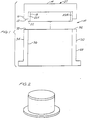
- the target assembly 10 to be manufactured comprises a target member 20 and a backing member 30.
- the target assembly is of a typical annular configuration such as may be employed in a suitable sputtering apparatus.
- the target member 20 has a lateral, e.g. upper, target surface 14 formed of material to be sputtered, and outer and inner side walls 16 and 18, respectively.
- the target member is provided with an inwardly extending shoulder 12 in the outer surface of the side wall at the lower end of the target member.
- the shoulder terminates in a transverse or downwardly extending lip 22.
- Backing member 30 is provided with side wall 28 having outer and inner surfaces 34 and 36, respectively, and a top surface 32.
- the side walls of the backing member are sized with respect to the shoulder on the target member so that the top surface 32 of the side wall may be positioned within the shoulder surface 12 and also abuts against lip 22; thus, end wall 28 is in surface-to-surface contact with the target member including the portions 12 and lip 22 thereof.
- the end wall is provided with close dimensions to cause a snug fit around the lip 22.
- the backing member and target After fitting the side walls of the backing member into position within the shoulder, as described, the backing member and target are firmly held in position and the surface-to-surface contact areas are welded by electron beam welding. Following welding, the inner surfaces of the backing member and target member are machined so as to remove the lip portion 22A to the target and provide a coextensive inner surface along the inner surfaces of the backing member and the target member.
- the outer surface of the side walls of both the backing and target members is also machined to final tolerances to also produce a coextensive outer surface.
- the use of the lip 22 in combination with electron beam welding of the target member and backing member are critical to manufacturing the target assembly with minimal distortion.
- the lip maintains the positioning of the backing member in contact with the target member during welding to minimize distortion during electron beam welding.
- Electron beam welding is also critical because it produces high quality welds with a narrow heat affected zone (HAZ).
- HAZ heat affected zone
- electron beam welding involves a low heat input into the members being welded and dispenses with the need of filler materials during joining.
- FIG. 3 Another embodiment of the invention is shown in Figure 3.
- a "deep dish” design is provided which allows operators of the sputtering equipment to shorten the dark space shielding that surrounds the target.
- the sputtering portion of this design would be made by precision forging or impact extrusion and would be made out of the same high purity alloys as the previously described design.
- the backing member would be electron beam welded to the target and advantageously would be also machined out of 2000 series aluminum alloys such as 2014-T6 tubing or plate.
- the assembly comprises a target member 40 and a backing member 42 with a stepped flange configuration and lip 44 to be removed by machining after assembly.
- the method of manufacturing this design is the same as described in connection with the Figure 1 design except that the machining of the outer surface is only necessary through the interface area between the backing member and the target member.
- a sputtering targets of high purity aluminum such as 1% Si, balance aluminum and 1% Si, .5% Cu, balance aluminum
- a shoulder as described extending inwardly from the outer surface and downwardly toward to the lower end of the target member. This resulted in an overlapping step joint 0.100-inches thick and 0.100-inches deep.
- the backing member was formed by machining commercially available 2014-T6 extruded, aluminum seamless tubing. Prior to welding the target member and backing member were machined such that they had a 0.005-inch (maximum) pressed fit at the shoulder and lip. The target member and backing member were held firmly in place by spot welding at a plurality of places, e.g., four places, with an electron beam prior to the final electron beam welding operation. The components were electron beam welded with full penetration from the exterior.
- the target assemblies were visually inspected and helium leak inspected for weld integrity. Shrinkage and distortion were also measured.
- the radial, i.e., diametral, shrinkage was in the range of 0.002-0.003-inches and the depth shrinkage was in the range of 0.002-0.005-inches. Thus, distortion was minimal.
- All aluminum electron beam welded target assemblies that is, target assemblies with target members and backing members made of material selected from the group of aluminum and aluminum alloys, of the design described produced by the foregoing method has been found to have the ability to withstand high water pressure and high sputter power levels.
- the method of the invention may also be used to produce target assemblies of other materials, such as target assemblies with target members and backing plates comprising: copper and copper alloys, titanium and titanium alloys or other metals where the target member and backing member are comprised of the same major constituent.
Landscapes
- Chemical & Material Sciences (AREA)
- Engineering & Computer Science (AREA)
- Mechanical Engineering (AREA)
- Physics & Mathematics (AREA)
- Plasma & Fusion (AREA)
- Analytical Chemistry (AREA)
- Chemical Kinetics & Catalysis (AREA)
- Materials Engineering (AREA)
- Metallurgy (AREA)
- Organic Chemistry (AREA)
- Physical Vapour Deposition (AREA)
- Welding Or Cutting Using Electron Beams (AREA)
Applications Claiming Priority (2)
| Application Number | Priority Date | Filing Date | Title |
|---|---|---|---|
| US07/728,249 US5143590A (en) | 1991-07-10 | 1991-07-10 | Method of manufacturing sputtering target assembly |
| US728249 | 1996-10-08 |
Publications (1)
| Publication Number | Publication Date |
|---|---|
| EP0522821A1 true EP0522821A1 (de) | 1993-01-13 |
Family
ID=24926049
Family Applications (1)
| Application Number | Title | Priority Date | Filing Date |
|---|---|---|---|
| EP92306201A Ceased EP0522821A1 (de) | 1991-07-10 | 1992-07-06 | Herstellungsmethode für Zerstäubungstarget |
Country Status (3)
| Country | Link |
|---|---|
| US (1) | US5143590A (de) |
| EP (1) | EP0522821A1 (de) |
| JP (1) | JPH05195217A (de) |
Cited By (1)
| Publication number | Priority date | Publication date | Assignee | Title |
|---|---|---|---|---|
| CN109807453A (zh) * | 2019-03-18 | 2019-05-28 | 东莞市欧莱溅射靶材有限公司 | 一种高纯铜旋转靶的端头焊接方法 |
Families Citing this family (32)
| Publication number | Priority date | Publication date | Assignee | Title |
|---|---|---|---|---|
| US5428882A (en) * | 1993-04-05 | 1995-07-04 | The Regents Of The University Of California | Process for the fabrication of aluminum metallized pyrolytic graphite sputtering targets |
| US5342496A (en) * | 1993-05-18 | 1994-08-30 | Tosoh Smd, Inc. | Method of welding sputtering target/backing plate assemblies |
| US5687600A (en) * | 1994-10-26 | 1997-11-18 | Johnson Matthey Electronics, Inc. | Metal sputtering target assembly |
| US5738770A (en) | 1996-06-21 | 1998-04-14 | Sony Corporation | Mechanically joined sputtering target and adapter therefor |
| RU2104130C1 (ru) * | 1996-08-01 | 1998-02-10 | Закрытое акционерное общество "Техно-ТМ" | Способ соединения элементов композиционной мишени из тугоплавкого и труднодеформируемого материалов |
| JPH10330929A (ja) * | 1997-05-28 | 1998-12-15 | Japan Energy Corp | スパッタリングタ−ゲット用バッキングプレ−ト及びスパッタリングタ−ゲット/バッキングプレ−ト組立体 |
| US6579431B1 (en) | 1998-01-14 | 2003-06-17 | Tosoh Smd, Inc. | Diffusion bonding of high purity metals and metal alloys to aluminum backing plates using nickel or nickel alloy interlayers |
| US6749103B1 (en) * | 1998-09-11 | 2004-06-15 | Tosoh Smd, Inc. | Low temperature sputter target bonding method and target assemblies produced thereby |
| US6348113B1 (en) | 1998-11-25 | 2002-02-19 | Cabot Corporation | High purity tantalum, products containing the same, and methods of making the same |
| EP1135233A4 (de) | 1998-12-03 | 2004-11-03 | Tosoh Smd Inc | Treffplatte und verfahren zu seiner herstellung |
| US6164519A (en) * | 1999-07-08 | 2000-12-26 | Praxair S.T. Technology, Inc. | Method of bonding a sputtering target to a backing plate |
| TW483793B (en) | 1999-07-12 | 2002-04-21 | Tosoh Smd Inc | Friction fit target assembly |
| US6283357B1 (en) * | 1999-08-03 | 2001-09-04 | Praxair S.T. Technology, Inc. | Fabrication of clad hollow cathode magnetron sputter targets |
| US6780794B2 (en) * | 2000-01-20 | 2004-08-24 | Honeywell International Inc. | Methods of bonding physical vapor deposition target materials to backing plate materials |
| US6698647B1 (en) * | 2000-03-10 | 2004-03-02 | Honeywell International Inc. | Aluminum-comprising target/backing plate structures |
| US6619537B1 (en) | 2000-06-12 | 2003-09-16 | Tosoh Smd, Inc. | Diffusion bonding of copper sputtering targets to backing plates using nickel alloy interlayers |
| US6725522B1 (en) | 2000-07-12 | 2004-04-27 | Tosoh Smd, Inc. | Method of assembling target and backing plates |
| EP1349698B1 (de) | 2000-12-15 | 2009-12-23 | Tosoh Smd, Inc. | Presspassungs-targetanordnung für hochleistungszerstäubungsvorgang |
| US20060065517A1 (en) * | 2002-06-14 | 2006-03-30 | Tosoh Smd, Inc. | Target and method of diffusion bonding target to backing plate |
| US6848608B2 (en) * | 2002-10-01 | 2005-02-01 | Cabot Corporation | Method of bonding sputtering target materials |
| TW200506080A (en) * | 2003-02-25 | 2005-02-16 | Cabot Corp | Method of forming sputtering target assembly and assemblies made therefrom |
| KR20060033013A (ko) * | 2003-07-14 | 2006-04-18 | 토소우 에스엠디, 인크 | 저 전도 백킹 플레이트를 갖는 스퍼터링 타겟 조립체 및 그제조 방법 |
| US7431195B2 (en) * | 2003-09-26 | 2008-10-07 | Praxair S.T. Technology, Inc. | Method for centering a sputter target onto a backing plate and the assembly thereof |
| US20050072668A1 (en) * | 2003-10-06 | 2005-04-07 | Heraeus, Inc. | Sputter target having modified surface texture |
| US20050236270A1 (en) * | 2004-04-23 | 2005-10-27 | Heraeus, Inc. | Controlled cooling of sputter targets |
| US20060102597A1 (en) * | 2004-11-16 | 2006-05-18 | Exponent, Inc. | Electron beam welding method and apparatus using controlled volumetric heating |
| DE102004058316A1 (de) * | 2004-12-02 | 2006-06-08 | W.C. Heraeus Gmbh | Rohrförmiges Sputtertarget |
| US7708868B2 (en) * | 2005-07-08 | 2010-05-04 | Tosoh Smd, Inc. | Variable thickness plate for forming variable wall thickness physical vapor deposition target |
| US8702919B2 (en) * | 2007-08-13 | 2014-04-22 | Honeywell International Inc. | Target designs and related methods for coupled target assemblies, methods of production and uses thereof |
| JP6624585B2 (ja) * | 2015-01-09 | 2019-12-25 | Jx金属株式会社 | スパッタリングターゲット−バッキングプレート接合体 |
| US11359273B2 (en) | 2015-08-03 | 2022-06-14 | Honeywell International Inc. | Frictionless forged aluminum alloy sputtering target with improved properties |
| US10900102B2 (en) | 2016-09-30 | 2021-01-26 | Honeywell International Inc. | High strength aluminum alloy backing plate and methods of making |
Citations (3)
| Publication number | Priority date | Publication date | Assignee | Title |
|---|---|---|---|---|
| US3794807A (en) * | 1972-04-10 | 1974-02-26 | Gen Electric | Method of beam welding dissimilar metal parts |
| US3949186A (en) * | 1973-09-28 | 1976-04-06 | Nippon Steel Corporation | Method for welding between metallic body and precision tube body |
| US5009765A (en) * | 1990-05-17 | 1991-04-23 | Tosoh Smd, Inc. | Sputter target design |
Family Cites Families (3)
| Publication number | Priority date | Publication date | Assignee | Title |
|---|---|---|---|---|
| DE2933835C2 (de) * | 1979-08-21 | 1987-02-19 | Siemens AG, 1000 Berlin und 8000 München | Verfahren zum Befestigen von in Scheiben- oder Plattenform vorliegenden Targetmaterialien auf Kühlteller für Aufstäubanlagen |
| US4290876A (en) * | 1980-06-05 | 1981-09-22 | Murata Manufacturing Co., Ltd. | Sputtering apparatus |
| US4885075A (en) * | 1987-01-27 | 1989-12-05 | Machine Technology, Inc. | Cooling device for a sputter target and source |
-
1991
- 1991-07-10 US US07/728,249 patent/US5143590A/en not_active Expired - Fee Related
-
1992
- 1992-06-03 JP JP4142797A patent/JPH05195217A/ja not_active Withdrawn
- 1992-07-06 EP EP92306201A patent/EP0522821A1/de not_active Ceased
Patent Citations (3)
| Publication number | Priority date | Publication date | Assignee | Title |
|---|---|---|---|---|
| US3794807A (en) * | 1972-04-10 | 1974-02-26 | Gen Electric | Method of beam welding dissimilar metal parts |
| US3949186A (en) * | 1973-09-28 | 1976-04-06 | Nippon Steel Corporation | Method for welding between metallic body and precision tube body |
| US5009765A (en) * | 1990-05-17 | 1991-04-23 | Tosoh Smd, Inc. | Sputter target design |
Cited By (1)
| Publication number | Priority date | Publication date | Assignee | Title |
|---|---|---|---|---|
| CN109807453A (zh) * | 2019-03-18 | 2019-05-28 | 东莞市欧莱溅射靶材有限公司 | 一种高纯铜旋转靶的端头焊接方法 |
Also Published As
| Publication number | Publication date |
|---|---|
| JPH05195217A (ja) | 1993-08-03 |
| US5143590A (en) | 1992-09-01 |
Similar Documents
| Publication | Publication Date | Title |
|---|---|---|
| US5143590A (en) | Method of manufacturing sputtering target assembly | |
| EP0500031A1 (de) | Verfahren zur Herstellung eines Zerstäubungstargets | |
| US7114643B2 (en) | Friction fit target assembly for high power sputtering operation | |
| KR100764269B1 (ko) | 스퍼터 타겟 조립체의 제조 방법 | |
| US5342496A (en) | Method of welding sputtering target/backing plate assemblies | |
| US6419806B1 (en) | Insert target assembly and method of making same | |
| EP2044611B1 (de) | Sputtertarget-anordnungen mit gesteuerter lötdicke | |
| US5009765A (en) | Sputter target design | |
| US8020748B2 (en) | Sputtering target assembly and method of making same | |
| US5963778A (en) | Method for producing near net shape planar sputtering targets and an intermediate therefor | |
| EP0630423B1 (de) | Verfahren zur verbindung einer sputter-targetträgerplatteneinheit | |
| TWI498435B (zh) | 具有低溫高強度接合的濺鍍靶材組合 | |
| US20040256226A1 (en) | Method and design for sputter target attachment to a backing plate | |
| US4777643A (en) | Composite rotary anode for x-ray tube and process for preparing the composite | |
| EP0117352A1 (de) | Verfahren zum Schweissen von Bauteilen auf der Basis von Aluminium und geschweisster Aufbau | |
| US4291104A (en) | Brazed corrosion resistant lined equipment | |
| JP3670008B2 (ja) | 気密ろう接合部の作成方法 | |
| KR100348437B1 (ko) | 스퍼터링타겟어셈블리의제조방법및새로운타겟어셈블리 | |
| US4700882A (en) | Composite rotary anode for X-ray tube and process for preparing the composite | |
| US4419415A (en) | Magnetic head comprising two spot welded metal plates | |
| RU2109606C1 (ru) | Способ изготовления паяных телескопических конструкций | |
| WO1997031739A1 (en) | Method for producing near net shape planar sputtering targets and an intermediate therefor | |
| EP0417455B1 (de) | Verfahren zur Herstellung von Magnetronanoden | |
| JP2878435B2 (ja) | チタン材と銅材との接合方法 | |
| Tulisiak | Electron beam application to welding space propulsion components |
Legal Events
| Date | Code | Title | Description |
|---|---|---|---|
| PUAI | Public reference made under article 153(3) epc to a published international application that has entered the european phase |
Free format text: ORIGINAL CODE: 0009012 |
|
| AK | Designated contracting states |
Kind code of ref document: A1 Designated state(s): DE FR GB IT |
|
| 17P | Request for examination filed |
Effective date: 19930601 |
|
| 17Q | First examination report despatched |
Effective date: 19940905 |
|
| STAA | Information on the status of an ep patent application or granted ep patent |
Free format text: STATUS: THE APPLICATION HAS BEEN REFUSED |
|
| 18R | Application refused |
Effective date: 19951225 |