EP0522835A2 - Vorrichtung zum Decodieren eines Bildsignals - Google Patents
Vorrichtung zum Decodieren eines Bildsignals Download PDFInfo
- Publication number
- EP0522835A2 EP0522835A2 EP92306247A EP92306247A EP0522835A2 EP 0522835 A2 EP0522835 A2 EP 0522835A2 EP 92306247 A EP92306247 A EP 92306247A EP 92306247 A EP92306247 A EP 92306247A EP 0522835 A2 EP0522835 A2 EP 0522835A2
- Authority
- EP
- European Patent Office
- Prior art keywords
- picture
- picture data
- buffer memory
- stored
- storage means
- Prior art date
- Legal status (The legal status is an assumption and is not a legal conclusion. Google has not performed a legal analysis and makes no representation as to the accuracy of the status listed.)
- Granted
Links
Images


Classifications
-
- H—ELECTRICITY
- H04—ELECTRIC COMMUNICATION TECHNIQUE
- H04N—PICTORIAL COMMUNICATION, e.g. TELEVISION
- H04N19/00—Methods or arrangements for coding, decoding, compressing or decompressing digital video signals
- H04N19/60—Methods or arrangements for coding, decoding, compressing or decompressing digital video signals using transform coding
- H04N19/61—Methods or arrangements for coding, decoding, compressing or decompressing digital video signals using transform coding in combination with predictive coding
-
- H—ELECTRICITY
- H04—ELECTRIC COMMUNICATION TECHNIQUE
- H04N—PICTORIAL COMMUNICATION, e.g. TELEVISION
- H04N19/00—Methods or arrangements for coding, decoding, compressing or decompressing digital video signals
- H04N19/50—Methods or arrangements for coding, decoding, compressing or decompressing digital video signals using predictive coding
- H04N19/503—Methods or arrangements for coding, decoding, compressing or decompressing digital video signals using predictive coding involving temporal prediction
- H04N19/51—Motion estimation or motion compensation
- H04N19/58—Motion compensation with long-term prediction, i.e. the reference frame for a current frame not being the temporally closest one
-
- H—ELECTRICITY
- H04—ELECTRIC COMMUNICATION TECHNIQUE
- H04N—PICTORIAL COMMUNICATION, e.g. TELEVISION
- H04N5/00—Details of television systems
- H04N5/76—Television signal recording
- H04N5/91—Television signal processing therefor
- H04N5/92—Transformation of the television signal for recording, e.g. modulation, frequency changing; Inverse transformation for playback
- H04N5/926—Transformation of the television signal for recording, e.g. modulation, frequency changing; Inverse transformation for playback by pulse code modulation
- H04N5/9261—Transformation of the television signal for recording, e.g. modulation, frequency changing; Inverse transformation for playback by pulse code modulation involving data reduction
- H04N5/9264—Transformation of the television signal for recording, e.g. modulation, frequency changing; Inverse transformation for playback by pulse code modulation involving data reduction using transform coding
-
- H—ELECTRICITY
- H04—ELECTRIC COMMUNICATION TECHNIQUE
- H04N—PICTORIAL COMMUNICATION, e.g. TELEVISION
- H04N5/00—Details of television systems
- H04N5/76—Television signal recording
- H04N5/84—Television signal recording using optical recording
- H04N5/85—Television signal recording using optical recording on discs or drums
Definitions
- the present invention relates to a video image data decoding apparatus (hereinafter briefly called “picture data decoder”) suitable for use for example in reproducing picture data compressed and recorded in a recording medium such as a disk.
- picture data decoder video image data decoding apparatus
- I picture intra coded picture
- P picture forward prediction coded picture
- the I picture is such that, when it is coded, uses a set of closed data within one area (one frame) of picture. Although the quantity of data increases when the I pictures are used, random access or high-speed reproduction can be achieved by scattering the I pictures in the picture data.
- the P picture forward prediction coded picture
- the P picture is such that uses an I picture or a P picture which has already been decoded and temporally located forward as the prediction picture (the picture serving as a reference in obtaining a differential).
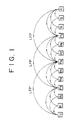
- the B picture (bidirectional prediction coded picture) is such that uses, as the prediction picture, three types of pictures: an I picture or a P picture which has already been decoded and temporally located forward, an I picture or a P picture which has already been decoded and temporally located backward, and an interpolated picture produced from both of them.
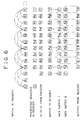
- the pictures denoted by numerals 0 to 9 are compressed as I0, B1, B2, P3, B4, B5, P6, B7, B8, and P9.
- character I denotes the I picture
- character P denotes the P picture
- character B denotes the B picture, respectively.
- the picture No. 0 is an I picture
- the picture Nos. 3, 6, and 9 are P pictures
- the picture Nos. 1, 2, 4, 5, 7, and 8 are B pictures.
- the picture I0 is generated from the data of itself
- the picture P3 is generated from the temporally forward picture I0
- the picture B1 is generated from both the temporally forward picture I0 and the temporally backward picture P3.
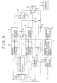
- FIG. 5 is a block diagram showing an example of structure of a conventional picture data decoder for decoding such compressed picture data as described above.
- An inverse VLC circuit 1 gives an inverse VLC (inverse Variable Length Coding) treatment to picture data supplied from a picture data encoder, not shown, and outputs the data to an inverse quantization circuit 2.
- the inverse quantization circuit 2 performs inverse zigzag scanning on the data undergone the inverse VLC treatment, gives an inverse quantization treatment thereto, and outputs the treated data to an inverse DCT circuit 3.
- the inverse DCT circuit 3 gives an inverse DCT (inverse Discrete Cosine Transform) treatment to the input data and outputs the data to an adder circuit 4.
- the adder circuit 4 there is present prediction picture data which has been selected by a switch 15 and input thereto through a gate 17, and this prediction picture data and the output data from the inverse DCT circuit 3 are added up and thereby decoded picture data is generated.
- a gate 5 When the output from the adder circuit 4 is an I picture or a P picture, a gate 5 is opened and the output is supplied, through a switch 6, to a buffer memory 7 or a buffer memory 8 to be stored therein.
- the inverse VLC circuit 1 is supplied with such data as motion vector data, quantization width data, and coding mode data, in addition to the picture data.
- the inverse VLC circuit 1 controls a timing circuit 16 in accordance with such data.
- the timing circuit 16 generates various timing signals in accordance with outputs from the inverse VLC circuit 1 to thereby operate the gate 5 and the gate 17 and turn switches 6, 9, 10, and 15 to the sides of predetermined contacts.
- the switches 9 and 10 are turned to the side of the contact a .
- the switch 6 is adapted to be alternately turned to the sides of the contacts a and b so that the pictures output from the adder circuit 4 (I pictures or P pictures) are alternately stored into the pair of buffer memories 7 and 8.
- the picture data in which pictures are arranged in the sequence of I0, B1, B2, P3, B4, B5, P6, B7, B8, P9 are processed in the encoder in the sequence of I0, P3, B1, B2, P6, B4, B5, P9, B7, B8. Accordingly, the data are input to the inverse VLC circuit 1 on the decoder side in the same sequence.
- decoded data of the picture I0 is stored into the buffer memory 7
- decoded data of the picture P3 is stored into the buffer memory 8.
- the data of the picture I0 in the buffer memory 7 is updated to data of the picture P6
- the data of the picture P3 in the buffer memory 8 is updated to data of the picture P9.
- the data of the picture I0 stored in the buffer memory 7 is motion compensated in accordance with a motion vector in a motion compensation circuit 12 to be supplied to an interpolation circuit 14.
- the data of P3 stored in the buffer memory 8 is motion compensated in accordance with a motion vector in a motion compensation circuit 13 to be supplied to the interpolation circuit 14.
- the interpolation circuit 14 combines the inputs from the motion compensation circuits 12 and 13 in the ratio according to data input from the inverse VLC circuit 1.
- the combined data is selected by the switch 15 and supplied to the adder circuit 4 through the contact b of the switch 15 and the gate 17.
- the adder circuit 4 adds up the data from the inverse DCT circuit 3 and the data selected by the switch 15 to thereby decode the picture B1 or B2.
- the switch 15 When the picture B1 or B2 is decoded only from the forward picture I0, the switch 15 is turned to the side of the contact a , and when it is decoded only from the backward picture P3, the switch 15 is turned to the side of the contact c , whereby the data of the picture I0 and the picture P3 are respectively supplied to the adder circuit 4.
- the switch 9 is adapted to be turned to the side opposite to the side of the switch 6. More specifically, when the switch 6 is turned to the side of the contact a (the contact b ), the switch 9 is turned to the side of the contact b (the contact a ). Therefore, when the switch 6 is turned to the side of the contact b and the picture P3 is stored into the buffer memory 8 after the picture I0 has been stored in the buffer memory 7, the switch 9 is turned to the side of the contact a . Since, at this time, the switch 10 is turned to the side of the contact a , the picture I0 is read from the buffer memory 7 and supplied, through the switches 9 and 10, to a display 11 to be displayed thereon.
- the switch 10 Since the switch 10 is turned to the side of the contact b when the picture B1 or B2 is output from the adder circuit 4, the picture B1 or B2 is supplied to the display 11. Then, the switch 9 is turned to the side of the contact b and the switch 10 is turned to the side of the contact a , whereby the picture P3 already stored in the buffer memory 8 is read out to be supplied to the display 11.
- the present invention has been made in view of the above described situation and an object of the present invention is to provide accurate reproduction of original pictures.
- a picture data decoder which comprises two or more storage means for storing two or more successive sets of decoded intra coded picture data or forward prediction coded picture data, storage control means for causing decoded intra coded picture data or forward prediction coded picture data to be sequentially stored in the two or more storage means, and generation means utilizing picture data stored in one of the two or more storage means for generating picture data to be stored into another storage means and also utilizing picture data stored in one storage means for generating picture data to be newly stored into the one storage means.
- the above storage means is constituted of a pair of buffer memories 7 and 8
- the storage control means is constituted of a switch 6
- the generation means is constituted of motion compensation circuits 12 and 13, an interpolation circuit 14, a switch 15, an adder circuit 4, etc.
- the picture data decoder as the first aspect of the present invention is characterized in that the generation means thereof is adapted to perform motion compensation when it utilizes the picture data stored in one storage means for generating picture data to be stored into another storage means, and not to perform motion compensation within a predetermined range when it utilizes picture data stored in one storage means for generating picture data to be newly stored into the one storage means.
- a picture data decoder which comprises a pair of storage means for storing decoded intra coded picture data or forward prediction coded picture data, delay means for delaying picture data to be supplied to the storage means by at least a period of time corresponding to motion compensation, storage control means for causing picture data delayed by the delay means to be alternately stored in the pair of storage means, and generation means for generating picture data to be newly stored into one storage means of the pair of storage means by utilizing picture data stored in the one storage means.
- the above storage means is constituted of buffer memories 7 and 8
- the delay means is constituted of a buffer memory 21
- the storage control means is constituted of a switch 6
- the generation means is constituted of motion compensation circuits 12 and 13, an interpolation circuit 14, a switch 15, an adder circuit 4, etc.
- picture data stored in one of the buffer memories 7 and 8 is utilized for generating picture data to be stored into the other of the buffer memories and, further, picture data stored in one of the buffer memories 7 and 8 is utilized for generating picture data to be newly stored in the one of the buffer memories. Therefore, more accurate picture reproduction can be attained.
- motion compensation is performed when picture data stored in one of the buffer memories 7 and 8 is utilized for generating picture data to be stored into the other of the buffer memories, and motion compensation is not performed when picture data stored in one of the buffer memories 7 and 8 is utilized for generating picture data to be newly stored in the one of the buffer memories. Therefore, it becomes possible to generate picture data to be newly stored into the buffer memory 7 or 8 by utilizing picture data stored in the same buffer memory.
- picture data are stored into the buffer memories 7 and 8 after being delayed in the buffer memory 21 by a period of time corresponding to motion compensation.
- the picture data stored in the buffer memory 7 (or 8) the picture data to be newly stored into the buffer memory 7 (or 8) is generated. Therefore, long forward prediction can be achieved while motion compensation is performed so that more accurate picture reproduction can be attained.
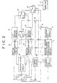
- FIG. 2 is a block diagram showing a structure of an embodiment of the picture data decoder of the present invention, in which corresponding parts to those in the arrangement of FIG. 5 are denoted by like reference numerals and, hence, description of the same will be generally omitted to avoid duplication. While the basic structure of the present embodiment is the same as that in the case of FIG. 5, the timing of the switch 15 provided by the timing circuit 16 is different from that in the case of FIG. 5.
- the picture P6 is decoded utilizing not only the forward picture P3 but also the still more forward picture I0.
- the picture P9 is decoded utilizing not only the forward picture P6 but also the still more forward picture P3.
- a long forward prediction is performed. Since other functioning than the above is the same as that in the arrangement of FIG. 5, description will be given below of the decoding process according to such long forward prediction.
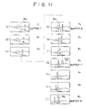
- the switch 6 when the data of the buffer memory 7 was to be updated, the switch 6 was turned to the side of the contact a and the switch 15 was turned to the side of the contact c (on the side of the other buffer memory 8). In the present embodiment, however, while the switch 6 is held turned to the side of the contact a , the switch 15 is turned to the side of the contact c at the timing during which the data of the other buffer memory 8 is utilized but it is turned to the side of the contact a (on the side of the buffer memory 7) at the timing during which the data of itself is utilized.
- the switch 6 was turned to the side of the contact b and the switch 15 was turned to the side of the contact a (on the side of the other buffer memory 7).
- the switch 15 is turned to the side of the contact a at the timing during which the data of the other buffer memory 7 is utilized but it is turned to the side of the contact c (on the side of the buffer memory 8) at the timing during which the data of itself is utilized.
- the picture in the area indicated by the window W1 in the picture P6 (the picture of the buildings in the background) can be obtained from the window W3 in the picture I0 one picture forward of the picture P3 (the P or I picture two pictures forward).
- the picture in the area indicated by the window W2 in the picture P9 (the picture of the buildings in the background) can be obtained from the window W4 in the picture P3 forward of the picture P6 (the P or I picture two pictures forward).
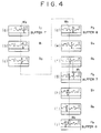
- FIG. 3 schematically shows a state in which data of the picture I0 stored in the buffer memory 7 are being rewritten by data of the picture P6.
- the data of the pixel shown in the center of the macro-block indicated by the thick solid line is about to be rewritten by new data.
- a short forward prediction e.g., where data is predicted from an I picture or a P picture one picture forward (not two or more pictures forward)
- a picture P3 is predicted from a picture I0 or a picture P6 is predicted from a picture P3
- motion compensation is performed in the range enclosed by the thick solid line.
- a long forward prediction e.g. where data is predicted from an I picture or a P picture two pictures forward
- motion compensation is forbidden within the range including such a region as indicated by slashes in FIG. 3.
- the buffer memories more than two in number can be provided. By such arrangement, it becomes possible to perform a longer forward prediction.
- the picture data decoder as the first aspect of the present invention, it is adapted such that not only picture data stored in one of the storage means is utilized for generating picture data to be stored in the other of the storage means but also picture data stored in one of the storage means is utilized for generating picture data to be newly stored into the same storage means. Accordingly, data can be used more effectively and long forward prediction can be performed so that more accurate picture reproduction can be achieved.
- the picture data decoder as the second aspect of the present invention, it is adapted such that motion compensation is performed when picture data stored in one of the storage means is utilized for generating picture data to be stored into the other of the storage means and motion compensation is not performed within a predetermined range when picture data stored in one of the storage means is utilized for generating picture data to be newly stored in the one of the storage means. Therefore, it becomes possible to utilize picture data stored in one of the storage means for generating picture data to be stored anew into the same storage means.
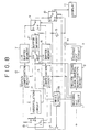
- FIG. 8 is a block diagram showing a structure of the present embodiment, in which corresponding parts to those in the arrangement of FIG. 6 are denoted by like reference numerals and, hence, description of the same will be generally omitted to avoid duplication.
- the present embodiment it is adapted such that the output of the gate 5 is stored into a buffer memory 21 and the picture data read from the buffer memory 21 is supplied to the buffer memory 7 or 8 through the switch 6.
- Other basic structure than the above is the same as that of FIG. 6. However, switching timing of the switch 15 and others given by the timing circuit 16 is different from that in the arrangement of FIG. 6.
- the present invention is characterized, as shown in FIG. 1, in that the picture P6 is decoded utilizing not only the forward picture P3 but also the still more forward picture I0. Similarly, the picture P9 is decoded utilizing not only the forward picture P6 but also the still more forward picture P3. In other words, in the present embodiment, a long forward prediction is performed. Since other functioning than the above is the same as that in the arrangement of FIG. 6, description will be given below as to the decoding process according to such long forward prediction.
- the switch 6 when the data of the buffer memory 7 was to be updated, the switch 6 was turned to the side of the contact a and the switch 15 was turned to the side of the contact c (on the side of the other buffer memory 8). In the present embodiment, however, while the switch 6 is held turned to the side of the contact a , the switch 15 is turned to the side of the contact c at the timing during which the data of the other buffer memory 8 is utilized but it is turned to the side of the contact a (on the side of the buffer memory 7) at the timing during which the data of itself is utilized.
- the switch 6 was turned to the side of the contact b and the switch 15 was turned to the side of the contact a (on the side of the other buffer memory 7).
- the switch 15 is turned to the side of the contact a at the timing during which the data of the other buffer memory 7 is utilized but it is turned to the side of the contact c (on the side of the buffer memory 8) at the timing during which the data of itself is utilized.
- the picture in the area indicated by the window W1 in the picture P6 (the picture of the range of mountains in the background) can be generated from the window W3 of the picture data in the picture I0 one picture forward of the picture P3 (the P or I picture two pictures forward).
- the picture in the area indicated by the window W2 in the picture P9 (the picture of the separate mountain in the background) can be generated from the window W4 of the picture data in the picture P3 forward of the picture P6 (the P or I picture two pictures forward).
- the picture data is delayed by the buffer memory 21 at least a period of time corresponding to the motion compensation process before it is input to the buffer memory 7 or 8.
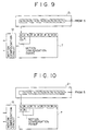
- FIG. 9 and FIG. 10 schematically show the states where the data of picture R (for example the picture I0) stored in the buffer memory 7 (or, the buffer memory 8) is being rewritten by the data of picture N (for example the picture P6) (the switch 6 is not shown in these diagrams for convenience).
- the pixel data of the first picture R in the buffer memory 7, as shown in FIG. 9 is updated by the pixel data of the new picture N, as shown in FIG. 10, the range of motion compensation enclosed by the thick solid line shifts from the state shown in FIG. 9 to the state shown in FIG. 10.
- the macro-block as the object of the processing within that range will sequentially shifts on the buffer memory from left to right and from top to bottom, and according to this movement, the range of motion compensation will also sequentially shift.
- the pixel data coming out of the range of motion compensation are sequentially updated by new pixel data.
- the capacity (delay time) of the buffer memory 21 is set up in accordance with the range of the motion vector and the number of the macro-blocks for each row.
- the picture data decoder of the present embodiment is adapted such that picture data are alternately stored into a pair of storage means after they are delayed at least a period of time corresponding to the motion compensation and the picture data to be newly stored in one of the pair of the storage means is generated by utilizing the picture data stored in the one of the pair of the storage means. Accordingly, it becomes possible to achieve a long forward prediction while performing motion compensation so that more accurate picture reproduction can be realized.
Landscapes
- Engineering & Computer Science (AREA)
- Multimedia (AREA)
- Signal Processing (AREA)
- Compression Or Coding Systems Of Tv Signals (AREA)
Applications Claiming Priority (4)
| Application Number | Priority Date | Filing Date | Title |
|---|---|---|---|
| JP198561/91 | 1991-07-12 | ||
| JP19856191A JP3057212B2 (ja) | 1991-07-12 | 1991-07-12 | 画像データ復号装置 |
| JP198562/91 | 1991-07-12 | ||
| JP3198562A JPH0522700A (ja) | 1991-07-12 | 1991-07-12 | 画像データ復号装置 |
Publications (3)
| Publication Number | Publication Date |
|---|---|
| EP0522835A2 true EP0522835A2 (de) | 1993-01-13 |
| EP0522835A3 EP0522835A3 (en) | 1993-09-22 |
| EP0522835B1 EP0522835B1 (de) | 1997-09-17 |
Family
ID=26511050
Family Applications (1)
| Application Number | Title | Priority Date | Filing Date |
|---|---|---|---|
| EP92306247A Expired - Lifetime EP0522835B1 (de) | 1991-07-12 | 1992-07-08 | Vorrichtung zum Decodieren eines Bildsignals |
Country Status (3)
| Country | Link |
|---|---|
| US (1) | US5321508A (de) |
| EP (1) | EP0522835B1 (de) |
| DE (1) | DE69222240T2 (de) |
Cited By (4)
| Publication number | Priority date | Publication date | Assignee | Title |
|---|---|---|---|---|
| EP0632388A1 (de) * | 1993-06-30 | 1995-01-04 | STMicroelectronics S.A. | Prozessorsystem, insbesondere für Bildverarbeitung mit einem Speicherbus von variabler Grösse |
| WO1996013128A1 (en) * | 1994-10-20 | 1996-05-02 | Thomson Consumer Electronics, Inc. | Digital vcr with trick play stream derivation |
| GB2311434A (en) * | 1996-03-21 | 1997-09-24 | Mitsubishi Electric Corp | Image decompressing apparatus with efficient image data storage |
| US5867625A (en) * | 1994-10-20 | 1999-02-02 | Thomson Consumer Electronics, Inc. | Digital VCR with trick play steam derivation |
Families Citing this family (7)
| Publication number | Priority date | Publication date | Assignee | Title |
|---|---|---|---|---|
| DE69329717T2 (de) * | 1992-10-09 | 2001-05-10 | Sony Corp., Tokio/Tokyo | Erzeugung und Aufnahme von Bildern |
| JP3282260B2 (ja) * | 1993-01-18 | 2002-05-13 | ソニー株式会社 | 画像再生装置及び方法 |
| US5982439A (en) * | 1993-07-30 | 1999-11-09 | British Telecommunications Public Limited Company | Coding image data |
| US5650823A (en) * | 1995-03-27 | 1997-07-22 | International Business Machines Corporation | Half pel motion estimation method for B pictures |
| JP3824678B2 (ja) | 1995-05-09 | 2006-09-20 | 株式会社ルネサステクノロジ | 画像復号表示装置 |
| US7782936B2 (en) | 2001-11-06 | 2010-08-24 | Panasonic Corporation | Moving picture coding method and moving picture decoding method |
| CN100551074C (zh) * | 2005-01-17 | 2009-10-14 | 松下电器产业株式会社 | 图像解码方法、图像解码装置和集成电路 |
Family Cites Families (5)
| Publication number | Priority date | Publication date | Assignee | Title |
|---|---|---|---|---|
| JPH0746864B2 (ja) * | 1984-08-22 | 1995-05-17 | ソニー株式会社 | 高能率符号化装置 |
| GB8724789D0 (en) * | 1987-10-19 | 1987-11-25 | British Telecomm | Signal coding |
| JPH07109990B2 (ja) * | 1989-04-27 | 1995-11-22 | 日本ビクター株式会社 | 適応型フレーム間予測符号化方法及び復号方法 |
| US4999705A (en) * | 1990-05-03 | 1991-03-12 | At&T Bell Laboratories | Three dimensional motion compensated video coding |
| US5175618A (en) * | 1990-10-31 | 1992-12-29 | Victor Company Of Japan, Ltd. | Compression method for interlace moving image signals |
-
1992
- 1992-07-08 EP EP92306247A patent/EP0522835B1/de not_active Expired - Lifetime
- 1992-07-08 DE DE69222240T patent/DE69222240T2/de not_active Expired - Lifetime
- 1992-07-10 US US07/911,513 patent/US5321508A/en not_active Expired - Lifetime
Cited By (6)
| Publication number | Priority date | Publication date | Assignee | Title |
|---|---|---|---|---|
| EP0632388A1 (de) * | 1993-06-30 | 1995-01-04 | STMicroelectronics S.A. | Prozessorsystem, insbesondere für Bildverarbeitung mit einem Speicherbus von variabler Grösse |
| WO1996013128A1 (en) * | 1994-10-20 | 1996-05-02 | Thomson Consumer Electronics, Inc. | Digital vcr with trick play stream derivation |
| US5867625A (en) * | 1994-10-20 | 1999-02-02 | Thomson Consumer Electronics, Inc. | Digital VCR with trick play steam derivation |
| GB2311434A (en) * | 1996-03-21 | 1997-09-24 | Mitsubishi Electric Corp | Image decompressing apparatus with efficient image data storage |
| US5850483A (en) * | 1996-03-21 | 1998-12-15 | Mitsubishi Denki Kabushiki Kaisha | Image decompressing apparatus with efficient image data transfer |
| GB2311434B (en) * | 1996-03-21 | 2000-01-12 | Mitsubishi Electric Corp | Image decompressing apparatus with efficient image data transfer |
Also Published As
| Publication number | Publication date |
|---|---|
| US5321508A (en) | 1994-06-14 |
| DE69222240D1 (de) | 1997-10-23 |
| DE69222240T2 (de) | 1998-02-05 |
| EP0522835A3 (en) | 1993-09-22 |
| EP0522835B1 (de) | 1997-09-17 |
Similar Documents
| Publication | Publication Date | Title |
|---|---|---|
| JP2570384B2 (ja) | 動画像信号の符号化・復号化方式 | |
| USRE44663E1 (en) | Image decoding apparatus for persistently storing reference images | |
| KR0151234B1 (ko) | 화상재생장치 및 화상복호장치 | |
| EP0700220B1 (de) | Datenwiedergabe | |
| US6009231A (en) | Reproduction of information using a ring buffer with read and write pointers separated from each other by substantially half of the total ring buffer capacity | |
| KR100402188B1 (ko) | 압축인코딩된이미지데이터를재생하는방법및장치 | |
| US5321508A (en) | Video image data recording apparatus | |
| KR100260475B1 (ko) | 화상 데이타 부호화 방법 및 장치, 화상 데이타 복호화 방법 및 장치 및 화상 기록 매체 | |
| KR100274922B1 (ko) | 화상 표시 장치 및 그 특수 재생 제어 장치 | |
| WO1990016130A1 (fr) | Codeur et decodeur d'images dynamiques | |
| JP3676525B2 (ja) | 動画像符号化復号化装置及びその方法 | |
| JP3607315B2 (ja) | 動画像復号化装置 | |
| JPH0522700A (ja) | 画像データ復号装置 | |
| JPH0730903A (ja) | 画像処理用メモリ集積回路 | |
| JP2801911B2 (ja) | 予測符号化による画像データの圧縮装置 | |
| JP3057212B2 (ja) | 画像データ復号装置 | |
| JP3733248B2 (ja) | 再生装置及びその方法 | |
| JPH08149410A (ja) | 画像記録再生装置 | |
| JP3506504B2 (ja) | ディジタル映像信号記録再生装置 | |
| JP3262464B2 (ja) | 画像復号化装置 | |
| US6778758B1 (en) | Image processing apparatus | |
| JP2523611B2 (ja) | 静止画再生装置 | |
| KR970008413B1 (ko) | 영상복호장치 | |
| JPH06339113A (ja) | 動画像記録再生装置 | |
| JPH04252690A (ja) | 映像信号符号化方法と映像信号符号化装置 |
Legal Events
| Date | Code | Title | Description |
|---|---|---|---|
| PUAI | Public reference made under article 153(3) epc to a published international application that has entered the european phase |
Free format text: ORIGINAL CODE: 0009012 |
|
| AK | Designated contracting states |
Kind code of ref document: A2 Designated state(s): DE FR GB |
|
| PUAL | Search report despatched |
Free format text: ORIGINAL CODE: 0009013 |
|
| AK | Designated contracting states |
Kind code of ref document: A3 Designated state(s): DE FR GB |
|
| 17P | Request for examination filed |
Effective date: 19940224 |
|
| 17Q | First examination report despatched |
Effective date: 19960304 |
|
| GRAG | Despatch of communication of intention to grant |
Free format text: ORIGINAL CODE: EPIDOS AGRA |
|
| GRAH | Despatch of communication of intention to grant a patent |
Free format text: ORIGINAL CODE: EPIDOS IGRA |
|
| GRAH | Despatch of communication of intention to grant a patent |
Free format text: ORIGINAL CODE: EPIDOS IGRA |
|
| GRAA | (expected) grant |
Free format text: ORIGINAL CODE: 0009210 |
|
| AK | Designated contracting states |
Kind code of ref document: B1 Designated state(s): DE FR GB |
|
| REF | Corresponds to: |
Ref document number: 69222240 Country of ref document: DE Date of ref document: 19971023 |
|
| ET | Fr: translation filed | ||
| PLBE | No opposition filed within time limit |
Free format text: ORIGINAL CODE: 0009261 |
|
| STAA | Information on the status of an ep patent application or granted ep patent |
Free format text: STATUS: NO OPPOSITION FILED WITHIN TIME LIMIT |
|
| 26N | No opposition filed | ||
| REG | Reference to a national code |
Ref country code: GB Ref legal event code: IF02 |
|
| PGFP | Annual fee paid to national office [announced via postgrant information from national office to epo] |
Ref country code: FR Payment date: 20110729 Year of fee payment: 20 |
|
| PGFP | Annual fee paid to national office [announced via postgrant information from national office to epo] |
Ref country code: GB Payment date: 20110721 Year of fee payment: 20 Ref country code: DE Payment date: 20110722 Year of fee payment: 20 |
|
| REG | Reference to a national code |
Ref country code: DE Ref legal event code: R071 Ref document number: 69222240 Country of ref document: DE |
|
| REG | Reference to a national code |
Ref country code: DE Ref legal event code: R071 Ref document number: 69222240 Country of ref document: DE |
|
| REG | Reference to a national code |
Ref country code: GB Ref legal event code: PE20 Expiry date: 20120707 |
|
| PG25 | Lapsed in a contracting state [announced via postgrant information from national office to epo] |
Ref country code: GB Free format text: LAPSE BECAUSE OF EXPIRATION OF PROTECTION Effective date: 20120707 Ref country code: DE Free format text: LAPSE BECAUSE OF EXPIRATION OF PROTECTION Effective date: 20120710 |