EP0523028B1 - Dispositif sur un moteur à combustion interne avec injection de carburant - Google Patents
Dispositif sur un moteur à combustion interne avec injection de carburant Download PDFInfo
- Publication number
- EP0523028B1 EP0523028B1 EP92850170A EP92850170A EP0523028B1 EP 0523028 B1 EP0523028 B1 EP 0523028B1 EP 92850170 A EP92850170 A EP 92850170A EP 92850170 A EP92850170 A EP 92850170A EP 0523028 B1 EP0523028 B1 EP 0523028B1
- Authority
- EP
- European Patent Office
- Prior art keywords
- air
- fuel injection
- internal combustion
- filter housing
- fuel
- Prior art date
- Legal status (The legal status is an assumption and is not a legal conclusion. Google has not performed a legal analysis and makes no representation as to the accuracy of the status listed.)
- Expired - Lifetime
Links
Images

Classifications
-
- F—MECHANICAL ENGINEERING; LIGHTING; HEATING; WEAPONS; BLASTING
- F02—COMBUSTION ENGINES; HOT-GAS OR COMBUSTION-PRODUCT ENGINE PLANTS
- F02M—SUPPLYING COMBUSTION ENGINES IN GENERAL WITH COMBUSTIBLE MIXTURES OR CONSTITUENTS THEREOF
- F02M35/00—Combustion-air cleaners, air intakes, intake silencers, or induction systems specially adapted for, or arranged on, internal-combustion engines
- F02M35/10—Air intakes; Induction systems
- F02M35/104—Intake manifolds
- F02M35/112—Intake manifolds for engines with cylinders all in one line
-
- F—MECHANICAL ENGINEERING; LIGHTING; HEATING; WEAPONS; BLASTING
- F02—COMBUSTION ENGINES; HOT-GAS OR COMBUSTION-PRODUCT ENGINE PLANTS
- F02B—INTERNAL-COMBUSTION PISTON ENGINES; COMBUSTION ENGINES IN GENERAL
- F02B27/00—Use of kinetic or wave energy of charge in induction systems, or of combustion residues in exhaust systems, for improving quantity of charge or for increasing removal of combustion residues
- F02B27/005—Oscillating pipes with charging achieved by arrangement, dimensions or shapes of intakes pipes or chambers; Ram air pipes
- F02B27/006—Oscillating pipes with charging achieved by arrangement, dimensions or shapes of intakes pipes or chambers; Ram air pipes of intake runners
-
- F—MECHANICAL ENGINEERING; LIGHTING; HEATING; WEAPONS; BLASTING
- F02—COMBUSTION ENGINES; HOT-GAS OR COMBUSTION-PRODUCT ENGINE PLANTS
- F02M—SUPPLYING COMBUSTION ENGINES IN GENERAL WITH COMBUSTIBLE MIXTURES OR CONSTITUENTS THEREOF
- F02M31/00—Apparatus for thermally treating combustion-air, fuel, or fuel-air mixture
- F02M31/20—Apparatus for thermally treating combustion-air, fuel, or fuel-air mixture for cooling
-
- F—MECHANICAL ENGINEERING; LIGHTING; HEATING; WEAPONS; BLASTING
- F02—COMBUSTION ENGINES; HOT-GAS OR COMBUSTION-PRODUCT ENGINE PLANTS
- F02M—SUPPLYING COMBUSTION ENGINES IN GENERAL WITH COMBUSTIBLE MIXTURES OR CONSTITUENTS THEREOF
- F02M35/00—Combustion-air cleaners, air intakes, intake silencers, or induction systems specially adapted for, or arranged on, internal-combustion engines
- F02M35/02—Air cleaners
- F02M35/04—Air cleaners specially arranged with respect to engine, to intake system or specially adapted to vehicle; Mounting thereon ; Combinations with other devices
-
- F—MECHANICAL ENGINEERING; LIGHTING; HEATING; WEAPONS; BLASTING
- F02—COMBUSTION ENGINES; HOT-GAS OR COMBUSTION-PRODUCT ENGINE PLANTS
- F02M—SUPPLYING COMBUSTION ENGINES IN GENERAL WITH COMBUSTIBLE MIXTURES OR CONSTITUENTS THEREOF
- F02M35/00—Combustion-air cleaners, air intakes, intake silencers, or induction systems specially adapted for, or arranged on, internal-combustion engines
- F02M35/10—Air intakes; Induction systems
- F02M35/10006—Air intakes; Induction systems characterised by the position of elements of the air intake system in direction of the air intake flow, i.e. between ambient air inlet and supply to the combustion chamber
- F02M35/10026—Plenum chambers
- F02M35/10039—Intake ducts situated partly within or on the plenum chamber housing
-
- F—MECHANICAL ENGINEERING; LIGHTING; HEATING; WEAPONS; BLASTING
- F02—COMBUSTION ENGINES; HOT-GAS OR COMBUSTION-PRODUCT ENGINE PLANTS
- F02M—SUPPLYING COMBUSTION ENGINES IN GENERAL WITH COMBUSTIBLE MIXTURES OR CONSTITUENTS THEREOF
- F02M35/00—Combustion-air cleaners, air intakes, intake silencers, or induction systems specially adapted for, or arranged on, internal-combustion engines
- F02M35/10—Air intakes; Induction systems
- F02M35/10209—Fluid connections to the air intake system; their arrangement of pipes, valves or the like
- F02M35/10216—Fuel injectors; Fuel pipes or rails; Fuel pumps or pressure regulators
-
- Y—GENERAL TAGGING OF NEW TECHNOLOGICAL DEVELOPMENTS; GENERAL TAGGING OF CROSS-SECTIONAL TECHNOLOGIES SPANNING OVER SEVERAL SECTIONS OF THE IPC; TECHNICAL SUBJECTS COVERED BY FORMER USPC CROSS-REFERENCE ART COLLECTIONS [XRACs] AND DIGESTS
- Y02—TECHNOLOGIES OR APPLICATIONS FOR MITIGATION OR ADAPTATION AGAINST CLIMATE CHANGE
- Y02T—CLIMATE CHANGE MITIGATION TECHNOLOGIES RELATED TO TRANSPORTATION
- Y02T10/00—Road transport of goods or passengers
- Y02T10/10—Internal combustion engine [ICE] based vehicles
- Y02T10/12—Improving ICE efficiencies
Definitions
- the present invention refers to a device at air filters for intake systems of internal combustion engines.
- All internal combustion engines have an air cleaner for the engine air intake.
- the main function of the air cleaner is to keep away dust and other particles from the carburettor and the cylinders.
- the air filter prevents dust or dirt from blocking jets and causing wear on pistons and cylinders.
- the cleaner also functions as a silencer, as it muffles the intake noise from the carburettor and the air cleaner housing suppresses the resonance which occurs due to the air pressure variations in the induction pipe.
- Such an arrangement is known, for example, from US-A-4 231 344
- the object of the present invention is to achieve an intake system of the type mentioned in the introduction, which exhibits a compact and space-saving construction and which is particularly adapted to internal combustion engines with direct fuel injection. This has according to the invention been achieved by the features of claim 1.
- Fig. 1 discloses a section through the intake system.
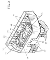
- Fig. 2 discloses in perspective the intake system according to the invention without filter, and without fuel injection valve.
- the intake system includes a filter housing 10 with an air intake 11, a filter element 12 and at least one air outlet tube 13.
- the filter housing 10 encases the replaceable, tubular filter element 12.
- the air intake 11 is placed at one gable of the filter housing 10 whereas the outlet tube 13 is connected to the tubular opening of the filter element 12. From the air intake 11 the air is led via an air space 14 extending around the filter element through the filter element 12 and to the air outlet tube.
- the outlet tube 13 comprises a throttle valve 15 and ends into a common space from where the induction air is distributed to the inlet manifolds 16 of the different engine cylinders.
- the inlet part 17 of these inlet manifolds 16 is horn-shaped and has an inlet opening 18, which communicates with the outlet tube 13, from where the induction air is led on to the inlet manifolds 16 via an air room in the horn 17.
- the inlet manifold has an upper mainly plane portion 19, against which a part of the filter housing 10 connects and it thus forms a part of its lower border. A very compact and space-saving construction is hereby achieved.
- FIG. 2 In fig. 2 is shown an intake system for a six cylinder engine, with equal number of inlet manifolds 16.
- the outlet tube 13 from the filter housing 10 is centrally located and the air is distributed from this point to all six inlet manifolds 16.
- the filter element 12 (not shown) is positioned direct on the package forming the intake system, whereby the upper portion 19 of the inlet manifold 16 forms the bottom of the filter housing.
- the portion 19 of the inlet manifolds 16 connecting to the filter housing 10 are curved but may also be plane, whereby the filter housing 10 is given a corresponding design.
- the filter element 12 itself is positioned against a sealing ring 22 in a groove 24, which has a shape corresponding to the cross section of the filter element, which in the example shown is oval.
- Fuel is supplied to the outlet part of the inlet manifold 16 via a fuel injection valve 20 which is screwed into a threaded bore 23 at the upper part of the inlet manifolds near the outlet end thereof.
- the fuel pipe 21 is positioned to a part of its length in the air space 14 of the filter housing 10, which air space communicates with the air intake 11.
- the supply pipe for the fuel can be embedded and form a unit with the induction pipe 16 and even in this case a part of the fuel pipe can be placed into the air space 14 of the filter housing 10.
Landscapes
- Engineering & Computer Science (AREA)
- Chemical & Material Sciences (AREA)
- Combustion & Propulsion (AREA)
- Mechanical Engineering (AREA)
- General Engineering & Computer Science (AREA)
- Fuel-Injection Apparatus (AREA)
- Exhaust Gas After Treatment (AREA)
Claims (1)
- Boîtier de filtre à air pour un moteur à combustion interne avec un collecteur d'admission d'air (16) et un système d'injection de carburant comprenant au moins un conduit d'alimentation en carburant (21) et au moins un injecteur de carburant,
caractérisé en ce que la base et la paroi latérale du boîtier de filtre à air (10) font partie intégrante du collecteur d'admission (16) et en ce qu'une partie du conduit d'alimentation en carburant (21) et l'injecteur de carburant (20) sont positionnés en amont de l'élément filtrant l'air (12) et à l'intérieur du boîtier de filtre à air (10).
Applications Claiming Priority (2)
| Application Number | Priority Date | Filing Date | Title |
|---|---|---|---|
| SE9102125 | 1991-07-08 | ||
| SE9102125A SE467670B (sv) | 1991-07-08 | 1991-07-08 | Anordning vid foerbraenningsmotor med braensleinsprutning |
Publications (3)
| Publication Number | Publication Date |
|---|---|
| EP0523028A2 EP0523028A2 (fr) | 1993-01-13 |
| EP0523028A3 EP0523028A3 (en) | 1993-05-19 |
| EP0523028B1 true EP0523028B1 (fr) | 1995-06-21 |
Family
ID=20383289
Family Applications (1)
| Application Number | Title | Priority Date | Filing Date |
|---|---|---|---|
| EP92850170A Expired - Lifetime EP0523028B1 (fr) | 1991-07-08 | 1992-07-07 | Dispositif sur un moteur à combustion interne avec injection de carburant |
Country Status (5)
| Country | Link |
|---|---|
| US (1) | US5259356A (fr) |
| EP (1) | EP0523028B1 (fr) |
| AT (1) | ATE124113T1 (fr) |
| DE (1) | DE69203047T2 (fr) |
| SE (1) | SE467670B (fr) |
Families Citing this family (19)
| Publication number | Priority date | Publication date | Assignee | Title |
|---|---|---|---|---|
| JPH0783132A (ja) * | 1993-09-17 | 1995-03-28 | Hitachi Ltd | 内燃機関の吸気装置 |
| US5575247A (en) * | 1995-02-01 | 1996-11-19 | Nippondenso Co., Ltd. | Air intake device for an internal combustion engine |
| JP3720402B2 (ja) * | 1995-02-17 | 2005-11-30 | ヤマハマリン株式会社 | 燃料噴射式船外機 |
| DE19521025A1 (de) * | 1995-06-13 | 1996-12-19 | Mann & Hummel Filter | Rohrmodul |
| DE19539078A1 (de) * | 1995-10-20 | 1997-04-24 | Mann & Hummel Filter | Saugrohr |
| DE19626251A1 (de) * | 1996-06-29 | 1998-01-08 | Bosch Gmbh Robert | Luftführungsanlage |
| US5713323A (en) * | 1996-10-04 | 1998-02-03 | Ford Motor Company | Integrated air/fuel induction system for an internal combustion engine |
| EP0892169B1 (fr) * | 1996-11-22 | 2002-06-12 | Denso Corporation | Dispositif d'admission d'un moteur a combustion interne |
| US6098586A (en) * | 1997-08-27 | 2000-08-08 | Siemens Canada Limited | Integrated intake manifold and air cleaner system |
| JP3589840B2 (ja) * | 1997-10-30 | 2004-11-17 | 株式会社デンソー | 内燃機関の吸気装置 |
| KR100527981B1 (ko) * | 1998-02-27 | 2006-03-20 | 다이하쓰고교가부시키가이샤 | 다기통내연기관에있어서의관성과급식흡기매니폴드의구조 |
| US6142123A (en) * | 1998-12-14 | 2000-11-07 | Cannondale Corporation | Motorcycle |
| DE19916530A1 (de) * | 1999-04-13 | 2000-10-19 | Mannesmann Vdo Ag | Einrichtung zur Versorgung einer Brennkraftmaschine eines Kraftfahrzeuges mit Kraftstoff |
| US6609491B2 (en) * | 2000-09-26 | 2003-08-26 | Honda Giken Kogyo Kabushiki Kaisha | Multi-cylinder engine and engine auxiliary parts mounting construction |
| JP2002235617A (ja) * | 2001-02-08 | 2002-08-23 | Denso Corp | 吸気装置 |
| US6886532B2 (en) * | 2001-03-13 | 2005-05-03 | Nissan Motor Co., Ltd. | Intake system of internal combustion engine |
| CN102996299B (zh) * | 2012-11-23 | 2016-01-20 | 优华劳斯汽车系统(上海)有限公司 | 一种多缸发动机的进气系统 |
| JP6809279B2 (ja) * | 2017-02-17 | 2021-01-06 | スズキ株式会社 | 内燃機関 |
| GB2576915A (en) * | 2018-09-06 | 2020-03-11 | Rcv Engines Ltd | A rotary valve internal combustion engine |
Family Cites Families (10)
| Publication number | Priority date | Publication date | Assignee | Title |
|---|---|---|---|---|
| IT1106986B (it) * | 1978-01-20 | 1985-11-18 | Fiat Spa | Sistema di alimentazione dell aria ad un motore diesel |
| JPS58190562A (ja) * | 1982-04-30 | 1983-11-07 | Toyota Motor Corp | 内燃機関の燃料供給装置 |
| US4526152A (en) * | 1984-01-12 | 1985-07-02 | Ford Motor Company | Low pressure low cost automotive type fuel injection system |
| EP0211419A3 (fr) * | 1985-08-06 | 1987-05-20 | Bayerische Motoren Werke Aktiengesellschaft, Patentabteilung AJ-3 | Dispositif échangeur de chaleur pour le carburant d'un moteur à combustion interne |
| DE3644552A1 (de) * | 1986-12-24 | 1988-07-07 | Pierburg Gmbh | Brennstoffverteilerleiste fuer ottomotoren |
| JPH01224447A (ja) * | 1988-03-02 | 1989-09-07 | Sanshin Ind Co Ltd | 燃料噴射式内燃機関 |
| US4924838A (en) * | 1989-04-26 | 1990-05-15 | Navistar International Transportation Corp. | Charge air fuel cooler |
| JP3043391B2 (ja) * | 1989-11-02 | 2000-05-22 | ヤマハ発動機株式会社 | 空気燃料噴射式2サイクルエンジンの遮音構造 |
| US5094194A (en) * | 1989-11-06 | 1992-03-10 | General Motors Corporation | Integrated induction system |
| JPH04113778U (ja) * | 1991-03-22 | 1992-10-06 | 本田技研工業株式会社 | 車両の燃料冷却装置 |
-
1991
- 1991-07-08 SE SE9102125A patent/SE467670B/sv not_active IP Right Cessation
-
1992
- 1992-07-07 EP EP92850170A patent/EP0523028B1/fr not_active Expired - Lifetime
- 1992-07-07 DE DE69203047T patent/DE69203047T2/de not_active Expired - Fee Related
- 1992-07-07 AT AT92850170T patent/ATE124113T1/de not_active IP Right Cessation
- 1992-07-08 US US07/910,693 patent/US5259356A/en not_active Expired - Lifetime
Also Published As
| Publication number | Publication date |
|---|---|
| DE69203047D1 (de) | 1995-07-27 |
| SE9102125L (sv) | 1992-08-24 |
| US5259356A (en) | 1993-11-09 |
| ATE124113T1 (de) | 1995-07-15 |
| DE69203047T2 (de) | 1996-02-29 |
| SE9102125D0 (sv) | 1991-07-08 |
| SE467670B (sv) | 1992-08-24 |
| EP0523028A3 (en) | 1993-05-19 |
| EP0523028A2 (fr) | 1993-01-13 |
Similar Documents
| Publication | Publication Date | Title |
|---|---|---|
| EP0523028B1 (fr) | Dispositif sur un moteur à combustion interne avec injection de carburant | |
| EP0523027A2 (fr) | Système d'admission pour moteurs à combustion interne | |
| US6712029B1 (en) | Cylinder for an internal combustion engine | |
| US6024066A (en) | Air-intake module for internal combustion engine | |
| EP1283352A3 (fr) | Dispositif d'admission pour moteur à combustion interne | |
| RU95110671A (ru) | Впускное устройство для двигателя внутреннего сгорания | |
| CN100549402C (zh) | 具有降低的噪音释放的四冲程内燃机 | |
| CN100410521C (zh) | 多缸内燃机 | |
| US5673655A (en) | V-type engine | |
| CA2036591A1 (fr) | Moteur a combustion interne | |
| EP1182343B1 (fr) | Agencement couvre-culasse pour un moteur à combustion interne | |
| US6318326B1 (en) | Vacuum device for combustion air supply of an internal combustion engine | |
| EP0508188A3 (en) | Suction system for an internal combustion engine with compression ignition | |
| US4433541A (en) | Secondary air introducing apparatus for internal combustion engine | |
| US6168484B1 (en) | Intake apparatus of outboard motor | |
| JP3747803B2 (ja) | 4サイクルv型エンジンを搭載した船外機 | |
| EP1722094A3 (fr) | Module d'admission d'air pour moteurs à combustion interne | |
| JP6962873B2 (ja) | エンジンの吸気構造 | |
| JP3608666B2 (ja) | 内燃機関の給気冷却器 | |
| KR200153731Y1 (ko) | 서지 탱크 장치 | |
| KR200143929Y1 (ko) | 디젤엔진의 브리딩개스 유입장치 | |
| JPH04292566A (ja) | 車両用エンジンのエアクリーナ | |
| JPH01294913A (ja) | エンジンの吸気装置 | |
| JPH0261310A (ja) | 内燃機関のブリーザ装置 | |
| RU93052935A (ru) | Двигатель внутреннего сгорания |
Legal Events
| Date | Code | Title | Description |
|---|---|---|---|
| PUAI | Public reference made under article 153(3) epc to a published international application that has entered the european phase |
Free format text: ORIGINAL CODE: 0009012 |
|
| AK | Designated contracting states |
Kind code of ref document: A2 Designated state(s): AT BE CH DE ES FR GB IT LI NL |
|
| PUAL | Search report despatched |
Free format text: ORIGINAL CODE: 0009013 |
|
| AK | Designated contracting states |
Kind code of ref document: A3 Designated state(s): AT BE CH DE ES FR GB IT LI NL |
|
| 17P | Request for examination filed |
Effective date: 19930715 |
|
| 17Q | First examination report despatched |
Effective date: 19940706 |
|
| GRAA | (expected) grant |
Free format text: ORIGINAL CODE: 0009210 |
|
| AK | Designated contracting states |
Kind code of ref document: B1 Designated state(s): AT BE CH DE ES FR GB IT LI NL |
|
| PG25 | Lapsed in a contracting state [announced via postgrant information from national office to epo] |
Ref country code: NL Free format text: LAPSE BECAUSE OF FAILURE TO SUBMIT A TRANSLATION OF THE DESCRIPTION OR TO PAY THE FEE WITHIN THE PRESCRIBED TIME-LIMIT Effective date: 19950621 Ref country code: LI Effective date: 19950621 Ref country code: CH Effective date: 19950621 Ref country code: BE Effective date: 19950621 Ref country code: AT Effective date: 19950621 |
|
| REF | Corresponds to: |
Ref document number: 124113 Country of ref document: AT Date of ref document: 19950715 Kind code of ref document: T |
|
| PGFP | Annual fee paid to national office [announced via postgrant information from national office to epo] |
Ref country code: AT Payment date: 19950713 Year of fee payment: 4 |
|
| PGFP | Annual fee paid to national office [announced via postgrant information from national office to epo] |
Ref country code: ES Payment date: 19950727 Year of fee payment: 4 |
|
| REF | Corresponds to: |
Ref document number: 69203047 Country of ref document: DE Date of ref document: 19950727 |
|
| ITF | It: translation for a ep patent filed | ||
| PGFP | Annual fee paid to national office [announced via postgrant information from national office to epo] |
Ref country code: BE Payment date: 19950911 Year of fee payment: 4 |
|
| REG | Reference to a national code |
Ref country code: CH Ref legal event code: PL |
|
| PG25 | Lapsed in a contracting state [announced via postgrant information from national office to epo] |
Ref country code: ES Free format text: LAPSE BECAUSE OF FAILURE TO SUBMIT A TRANSLATION OF THE DESCRIPTION OR TO PAY THE FEE WITHIN THE PRESCRIBED TIME-LIMIT Effective date: 19951002 |
|
| ET | Fr: translation filed | ||
| NLV1 | Nl: lapsed or annulled due to failure to fulfill the requirements of art. 29p and 29m of the patents act | ||
| PLBE | No opposition filed within time limit |
Free format text: ORIGINAL CODE: 0009261 |
|
| 26N | No opposition filed | ||
| REG | Reference to a national code |
Ref country code: GB Ref legal event code: IF02 |
|
| PGFP | Annual fee paid to national office [announced via postgrant information from national office to epo] |
Ref country code: FR Payment date: 20040702 Year of fee payment: 13 |
|
| PG25 | Lapsed in a contracting state [announced via postgrant information from national office to epo] |
Ref country code: IT Free format text: LAPSE BECAUSE OF NON-PAYMENT OF DUE FEES Effective date: 20050707 |
|
| PG25 | Lapsed in a contracting state [announced via postgrant information from national office to epo] |
Ref country code: FR Free format text: LAPSE BECAUSE OF NON-PAYMENT OF DUE FEES Effective date: 20060331 |
|
| REG | Reference to a national code |
Ref country code: FR Ref legal event code: ST Effective date: 20060331 |
|
| PGFP | Annual fee paid to national office [announced via postgrant information from national office to epo] |
Ref country code: DE Payment date: 20080731 Year of fee payment: 17 |
|
| PGFP | Annual fee paid to national office [announced via postgrant information from national office to epo] |
Ref country code: GB Payment date: 20080616 Year of fee payment: 17 |
|
| GBPC | Gb: european patent ceased through non-payment of renewal fee |
Effective date: 20090707 |
|
| PG25 | Lapsed in a contracting state [announced via postgrant information from national office to epo] |
Ref country code: GB Free format text: LAPSE BECAUSE OF NON-PAYMENT OF DUE FEES Effective date: 20090707 |
|
| PG25 | Lapsed in a contracting state [announced via postgrant information from national office to epo] |
Ref country code: DE Free format text: LAPSE BECAUSE OF NON-PAYMENT OF DUE FEES Effective date: 20100202 |