EP0523265A1 - Elément de combustible nucléaire avec générateur de tourbillon - Google Patents
Elément de combustible nucléaire avec générateur de tourbillon Download PDFInfo
- Publication number
- EP0523265A1 EP0523265A1 EP91111957A EP91111957A EP0523265A1 EP 0523265 A1 EP0523265 A1 EP 0523265A1 EP 91111957 A EP91111957 A EP 91111957A EP 91111957 A EP91111957 A EP 91111957A EP 0523265 A1 EP0523265 A1 EP 0523265A1
- Authority
- EP
- European Patent Office
- Prior art keywords
- fuel
- nuclear reactor
- cylinder body
- fuel rod
- length
- Prior art date
- Legal status (The legal status is an assumption and is not a legal conclusion. Google has not performed a legal analysis and makes no representation as to the accuracy of the status listed.)
- Withdrawn
Links
- 239000000446 fuel Substances 0.000 title claims abstract description 115
- 239000003758 nuclear fuel Substances 0.000 claims abstract description 45
- 125000006850 spacer group Chemical group 0.000 claims description 20
- 238000005452 bending Methods 0.000 claims description 2
- 238000009835 boiling Methods 0.000 abstract description 13
- 230000007704 transition Effects 0.000 abstract description 2
- 238000002791 soaking Methods 0.000 abstract 1
- XLYOFNOQVPJJNP-UHFFFAOYSA-N water Substances O XLYOFNOQVPJJNP-UHFFFAOYSA-N 0.000 description 19
- 239000007788 liquid Substances 0.000 description 17
- 238000005253 cladding Methods 0.000 description 7
- 239000002826 coolant Substances 0.000 description 6
- 239000012071 phase Substances 0.000 description 4
- 229910001093 Zr alloy Inorganic materials 0.000 description 3
- 229910052751 metal Inorganic materials 0.000 description 3
- 239000002184 metal Substances 0.000 description 3
- 230000015572 biosynthetic process Effects 0.000 description 1
- 239000007791 liquid phase Substances 0.000 description 1
- 239000000203 mixture Substances 0.000 description 1
- 238000012986 modification Methods 0.000 description 1
- 230000004048 modification Effects 0.000 description 1
- 238000013021 overheating Methods 0.000 description 1
- 238000000926 separation method Methods 0.000 description 1
- 239000012808 vapor phase Substances 0.000 description 1
- 238000009736 wetting Methods 0.000 description 1
Images

Classifications
-
- G—PHYSICS
- G21—NUCLEAR PHYSICS; NUCLEAR ENGINEERING
- G21C—NUCLEAR REACTORS
- G21C3/00—Reactor fuel elements and their assemblies; Selection of substances for use as reactor fuel elements
- G21C3/30—Assemblies of a number of fuel elements in the form of a rigid unit
- G21C3/32—Bundles of parallel pin-, rod-, or tube-shaped fuel elements
- G21C3/322—Means to influence the coolant flow through or around the bundles
-
- Y—GENERAL TAGGING OF NEW TECHNOLOGICAL DEVELOPMENTS; GENERAL TAGGING OF CROSS-SECTIONAL TECHNOLOGIES SPANNING OVER SEVERAL SECTIONS OF THE IPC; TECHNICAL SUBJECTS COVERED BY FORMER USPC CROSS-REFERENCE ART COLLECTIONS [XRACs] AND DIGESTS
- Y02—TECHNOLOGIES OR APPLICATIONS FOR MITIGATION OR ADAPTATION AGAINST CLIMATE CHANGE
- Y02E—REDUCTION OF GREENHOUSE GAS [GHG] EMISSIONS, RELATED TO ENERGY GENERATION, TRANSMISSION OR DISTRIBUTION
- Y02E30/00—Energy generation of nuclear origin
- Y02E30/30—Nuclear fission reactors
Definitions
- the invention relates to a nuclear reactor fuel element according to the preamble of patent claims 1 and 10.
- Such a nuclear reactor fuel element is known from Japanese laid-open publication 63-144 219.
- This nuclear reactor fuel element is intended for a boiling water nuclear reactor, and the swirl generator at the upper end of the part-length rod is a sheet metal twisted around the longitudinal axis of this part-length fuel rod.
- This twisted sheet metal in the two-phase area of the nuclear reactor fuel element in a boiling water nuclear reactor flushes the neighboring fuel rods, which protrude above the part-length fuel rod, with liquid water and ensures the moderation of neutrons.
- the invention has for its object to make the wetting of the fuel rods adjacent to the part-length fuel rod even more intense and thereby the boiling transfer rate, i.e. to increase the thermal power of the neighboring fuel rods in the boiling water reactor which protrude above the part-length fuel rod, in which drying-out of the liquid film and associated local overheating can occur on the outer surfaces of the cladding tubes of these fuel rods.
- a nuclear reactor fuel element of the type mentioned at the outset has the features of the characterizing part of patent claim 1 or 10.
- this nuclear reactor fuel element not only causes a relatively low pressure drop in the coolant flowing through the nuclear reactor fuel element, but also the guide vanes on the outer circumferential surface of the coaxial cylinder body or the inclined metal tabs on the end face of the upper end of the part-long fuel rod, in particular, detect the liquid film on the part-long fuel rod flows down to its top and wets it. This liquid film breaks off at the top of the part-length fuel rod, and the liquid is subjected to an intense swirl in the coolant flow in the boiling water nuclear reactor, which separates liquid droplets from the steam.
- Claim 6 is directed to a particularly advantageous development of the nuclear reactor fuel element according to claim 1, by which the separation of vapor and liquid phase within the nuclear reactor fuel element is effectively maintained in the two-phase region of a boiling-water nuclear reactor.
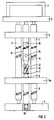
- Each nuclear reactor fuel element has a fuel element head 2 with a holding bracket 3 and a fuel element foot 4.
- the fuel assembly head 2 and the fuel assembly foot 4 each have a square cross section and passage openings in the longitudinal direction of the nuclear reactor fuel assembly. These passage openings are intended for a coolant that flows through the nuclear reactor fuel element in a boiling water nuclear reactor in the longitudinal direction, seen from the fuel element base 4 to the fuel element head 2.
- a plurality of lattice-shaped spacers 5 are provided between the fuel assembly head 2 and the fuel assembly foot 4, which are also square and have a cross section parallel to the square cross section of the fuel assembly head 2 and the fuel assembly foot 4. These grid-shaped spacers 5 are at a distance from one another as seen in the longitudinal direction of the nuclear reactor fuel element.
- the grid-shaped spacers 5 also have meshes, and a fuel rod 7, which contains nuclear fuel in a cladding tube made of a zirconium alloy and sealed at both ends, passes through each mesh. Only two of these fuel rods 7 are shown in the nuclear reactor fuel elements according to FIGS. 1 and 2.
- Such a nuclear reactor fuel element can have a series of so-called support rods, that is fuel rods 7 which have threaded bolts at both ends with which they are screwed to the fuel element head 2 and to the fuel element foot 4.
- the other fuel rods 7 engage loosely with bolts located at their two ends in bushings in the fuel element head 2 and fuel element foot 4. They can each additionally be prestressed with pressure, not shown Coil spring to be fixed, which sit on the bolts which engage in the bushings in the fuel assembly head 2 on the inside of the fuel assembly head 2 and are supported on this inside and on the fuel rod 7 concerned.
- a water pipe can be provided at both ends, which is screwed with one end to the fuel element head 2 and with the other end to the fuel element foot 3 and thus takes over the supporting function in the nuclear reactor fuel element.
- the fuel rods 7 only loosely engage in bushings in the fuel assembly head 2 at one end, and, as shown in FIGS. 1 and 2, they rest on the fuel assembly foot 4.
- the fuel rods 7 are non-positively held in the individual meshes of the spacers 7 by springs and rigid knobs located on the spacers, which cannot be seen in the drawing.
- the fuel rods 7 with the lattice-shaped spacers 5 are located in an elongated fuel element box, not shown, made of a zirconium alloy.
- This fuel assembly box also has a square cross section and is open at both ends. At one open end, this fuel assembly box lies with the inside on the side of the fuel assembly head 2 and at the other end on the side of the fuel assembly foot 4.
- a part-long fuel rod 8 also contains nuclear fuel in a cladding tube made of a zirconium alloy and sealed at both ends. At one end of this fuel rod 8 there is a threaded bolt 19 with which the part-length fuel rod 8 is screwed to the fuel element base 4. This part length Fuel rod 8 is also passed through a mesh of the spacers 5 until it projects shorter over an upper side of the spacer 5a between this upper side and the head part 2 than neighboring fuel rods 7, which extend with one end to the fuel element head 2.
- the part-long fuel rod 8 forms a coaxial, sharp-edged step 9.
- the outer diameter of this step 9 is larger than the outer diameter with which the part-long fuel rod 8 tapers continuously and finally with a continuously tapered outer diameter onto a coaxial cylinder body 10 of a swirl generator, which is attached to the top of the part-length fuel rod 8 above the top of the spacer 5a.
- a coaxial, sharp-edged step 11 is also formed at the point of impact of the part-length fuel rod 8 on the cylinder body 10. This step 11 has an outer diameter that is larger than the tapered outer diameter with which the part-length fuel rod 8 meets the step 11.
- the coaxial cylinder body 10 has on its outer lateral surface four guide vanes 12 which run helically with respect to the longitudinal axis of the cylinder body 10. Two adjacent guide vanes 12 each have the same angular distance 90 ° from one another with respect to the longitudinal axis of the cylinder body 10.
- the upper end of the cylinder body 10 finally merges into a coaxial engagement bolt 13, on which a tool can engage, with which the part-length fuel rod 8 can be screwed or unscrewed on the fuel element base 4 and with which the part-length fuel rod 8 can be moved in the longitudinal direction of the nuclear reactor fuel element.
- the outside diameter of the guide vanes 12 is advantageously equal to the outside diameter of the part-length fuel rod 8, so that the part-length fuel rod 8 can be moved over its entire length through the mesh of the spacers 5.
- liquid coolant consisting of water flows through the passages in the fuel element base 4 into the nuclear reactor fuel element, which is provided with the fuel element box (not shown).
- the two-phase region begins approximately at the level of the spacer 5a, and because of the swirl generated by the blades 12 of the swirl generator, droplets of liquid water are thrown outwards under the influence of the centrifugal force.
- the water droplets rain down over the part-length fuel rod 8 essentially on the outside of the cladding tubes of the fuel rods 7 adjacent to the part-length fuel rod 8 and reinforce the liquid film located on the outer surface of these cladding tubes, while water vapor is essentially above the longitudinal axis of the part-length fuel rod 8 part-length fuel rod 8 accumulates. This steam can finally escape through the bushings on the fuel assembly head 2 in the longitudinal direction of the nuclear reactor fuel assembly.
- the nuclear reactor fuel element according to FIG. 2 differs from the nuclear reactor fuel element according to FIG. 1 in particular in that a tube 14, which is coaxial to the part-long fuel rod 8, is placed on the engagement bolt 13 in FIG Spacer 5a and the fuel assembly 2 located spacer 5 is guided.
- This Tube 14 advantageously has the same outer diameter as the partial-length fuel rod 8.
- the tube 14 has a bolt at the top end like the fuel rods 7, with which it loosely engages in a passage in the fuel assembly head 2.
- the part-length fuel rod 8 can also stand on the fuel element base 4 with one end, as shown in FIG. 2 for the fuel rods 7.
- the tube 14 At the end of the tube which is adjacent to the cylinder body 10, the tube 14 has radial steam inlet openings 15 and at the other end in FIG. 2 there is an undetectable steam outlet opening which is directed parallel to the longitudinal axis of the tube 14.
- the steam which is separated as a result of the swirl generated by the guide vanes 10 in the coolant over the part-long fuel rod 8, passes through the steam inlet openings 15 into the tube 14, where it collects and cannot mix again with the liquid droplets thrown outwards.
- the outer diameter tapers continuously at one or more points of the tube 14 in the longitudinal direction of the tube 14 away from the cylinder body 10 to a coaxial, sharp-edged step 16 with an outer diameter that is larger than the tapered outer diameter.
- a liquid film which flows on the outside of the tube 14 in the direction of the fuel assembly head 2 can be torn open.
- the liquid droplets formed by the tearing open of the liquid film at the sharp-edged step 16 are again thrown outwards and thus also rain onto the outer surfaces of the adjacent fuel rods 7. This causes them to become Boiling transition performance further improved.
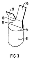
- Figure 3 shows another embodiment of the upper end of the part-length rod 8 in the nuclear reactor fuel element according to Figure 1.
- the top end shown in Figure 3 differs from the top end of the part-length rod 8 in Figure 1 in particular in that the coaxial sharp-edged step 9 by a to the longitudinal axis of the part-length rod 8 rectangular end face of this part-length rod 8 is formed.
- a flat sheet 17 is attached to this end face and is located in a plane formed by the axis of the part-long rod 8 and a diameter of the end face. This sheet 17 is slotted along this axis.
- This sheet 17 also forms two flags 20 and 21 which are inclined in the opposite direction to a bending line 18 parallel to the diameter of the end face.
- a second sheet of this type can advantageously also be arranged on the end face and, for example, have an angular distance of 90 ° with respect to the axis of the part-length fuel rod 8 from the first sheet.
- the sheet 17 according to FIG. 3 can also be arranged on the end face of a separate cylinder body attached to the upper end of the part-length fuel rod 8.
Landscapes
- Physics & Mathematics (AREA)
- Engineering & Computer Science (AREA)
- Plasma & Fusion (AREA)
- General Engineering & Computer Science (AREA)
- High Energy & Nuclear Physics (AREA)
- Monitoring And Testing Of Nuclear Reactors (AREA)
Priority Applications (1)
| Application Number | Priority Date | Filing Date | Title |
|---|---|---|---|
| EP91111957A EP0523265A1 (fr) | 1991-07-17 | 1991-07-17 | Elément de combustible nucléaire avec générateur de tourbillon |
Applications Claiming Priority (1)
| Application Number | Priority Date | Filing Date | Title |
|---|---|---|---|
| EP91111957A EP0523265A1 (fr) | 1991-07-17 | 1991-07-17 | Elément de combustible nucléaire avec générateur de tourbillon |
Publications (1)
| Publication Number | Publication Date |
|---|---|
| EP0523265A1 true EP0523265A1 (fr) | 1993-01-20 |
Family
ID=8206939
Family Applications (1)
| Application Number | Title | Priority Date | Filing Date |
|---|---|---|---|
| EP91111957A Withdrawn EP0523265A1 (fr) | 1991-07-17 | 1991-07-17 | Elément de combustible nucléaire avec générateur de tourbillon |
Country Status (1)
| Country | Link |
|---|---|
| EP (1) | EP0523265A1 (fr) |
Cited By (5)
| Publication number | Priority date | Publication date | Assignee | Title |
|---|---|---|---|---|
| EP0560169A1 (fr) * | 1992-03-13 | 1993-09-15 | Siemens Power Corporation | Système d'évacuation de caloporteur combiné à un barreau de combustible pour réacteur à eau légère |
| EP0619581A1 (fr) * | 1993-04-05 | 1994-10-12 | General Electric Company | Puissance critique optimisée dans un assemblage combustible avec barreaux à longueur partielle |
| EP0605816A3 (fr) * | 1992-12-17 | 1994-11-17 | Siemens Power Corp | Assemblage du combustible nucléaire. |
| US5875224A (en) * | 1997-09-02 | 1999-02-23 | General Electric Company | Swirler attachment for a spacer of a nuclear fuel bundle |
| US6148054A (en) * | 1998-11-09 | 2000-11-14 | General Electric Company | Removable separation devices for nuclear fuel bundles |
Citations (4)
| Publication number | Priority date | Publication date | Assignee | Title |
|---|---|---|---|---|
| FR1585673A (fr) * | 1967-09-07 | 1970-01-30 | ||
| FR2349825A1 (fr) * | 1976-04-30 | 1977-11-25 | Interatom | Installation destinee a realiser, dans un fluide en ecoulement, notamment dans le cas d'un reacteur nucleaire, des conditions permettant de mesurer une temperature representative |
| EP0240894A2 (fr) * | 1986-04-10 | 1987-10-14 | Siemens Aktiengesellschaft | "Water rod" avancé pour les réacteurs à eau bouillante |
| JPS63144290A (ja) * | 1986-12-09 | 1988-06-16 | 株式会社東芝 | 原子炉燃料集合体 |
-
1991
- 1991-07-17 EP EP91111957A patent/EP0523265A1/fr not_active Withdrawn
Patent Citations (4)
| Publication number | Priority date | Publication date | Assignee | Title |
|---|---|---|---|---|
| FR1585673A (fr) * | 1967-09-07 | 1970-01-30 | ||
| FR2349825A1 (fr) * | 1976-04-30 | 1977-11-25 | Interatom | Installation destinee a realiser, dans un fluide en ecoulement, notamment dans le cas d'un reacteur nucleaire, des conditions permettant de mesurer une temperature representative |
| EP0240894A2 (fr) * | 1986-04-10 | 1987-10-14 | Siemens Aktiengesellschaft | "Water rod" avancé pour les réacteurs à eau bouillante |
| JPS63144290A (ja) * | 1986-12-09 | 1988-06-16 | 株式会社東芝 | 原子炉燃料集合体 |
Cited By (10)
| Publication number | Priority date | Publication date | Assignee | Title |
|---|---|---|---|---|
| US5416812A (en) * | 1991-05-17 | 1995-05-16 | General Electric Company | Optimized critical power in a fuel bundle with part length rods |
| EP0560169A1 (fr) * | 1992-03-13 | 1993-09-15 | Siemens Power Corporation | Système d'évacuation de caloporteur combiné à un barreau de combustible pour réacteur à eau légère |
| US5345485A (en) * | 1992-03-13 | 1994-09-06 | Siemens Power Corporation | Coolant vent fuel rod for a light water reactor |
| US5375153A (en) * | 1992-03-13 | 1994-12-20 | Siemens Power Corporation | Coolant vent fuel rod and part length fuel rod having a reflex upper end fitting for a light water reactor |
| US5384815A (en) * | 1992-03-13 | 1995-01-24 | Siemens Power Corporation | Hydraulic resistance strip for a light water reactor |
| US5491733A (en) * | 1992-03-13 | 1996-02-13 | Siemens Power Corporation | Nuclear fuel rod assembly apparatus |
| EP0605816A3 (fr) * | 1992-12-17 | 1994-11-17 | Siemens Power Corp | Assemblage du combustible nucléaire. |
| EP0619581A1 (fr) * | 1993-04-05 | 1994-10-12 | General Electric Company | Puissance critique optimisée dans un assemblage combustible avec barreaux à longueur partielle |
| US5875224A (en) * | 1997-09-02 | 1999-02-23 | General Electric Company | Swirler attachment for a spacer of a nuclear fuel bundle |
| US6148054A (en) * | 1998-11-09 | 2000-11-14 | General Electric Company | Removable separation devices for nuclear fuel bundles |
Similar Documents
| Publication | Publication Date | Title |
|---|---|---|
| EP0517750B1 (fr) | Reacteur nucleaire a eau bouillante et element combustible pour ce reacteur nucleaire a eau bouillante | |
| DE69408013T2 (de) | Trümmerrückhaltevorrichtung für Siedewasserreaktor | |
| DE3139823C2 (de) | Brennstoffbündel | |
| DE1764140A1 (de) | Brutreaktor | |
| CH694304A5 (de) | Dampfwasserabscheider. | |
| DE2040416A1 (de) | Brennstoffanordnung fuer einen Kernreaktor | |
| DE69010842T2 (de) | Kernbrennstoffbündel für einen Siedewasserreaktor. | |
| DE69504588T2 (de) | Filter für Siedewasserkernreaktorbrennstabbündel | |
| DE69715620T2 (de) | Kernbrennstabbündel | |
| DE3427372A1 (de) | Brennelementbuegel fuer einen siedewasserreaktor | |
| DE69211875T2 (de) | Dampfablassrohr für Siedewasserreaktorbrennelement | |
| DE68902757T2 (de) | Vorrichtung zur kontrolle des kuehlmittelstromes zu einem und durch einen nuklearbrennstoffbuendel. | |
| DE4401602A1 (de) | Brennstoffanordnung einschließlich Ablenkschaufeln zum Ablenken einer Komponente eines Flüssigkeitsstroms, der entlang einer solchen Brennstoffanordnung fließt | |
| DE1082992B (de) | Zentrifugal-Wasserabscheider fuer Dampfzellen eines Siedewasser-Kernreaktors | |
| DE69210086T2 (de) | Teillängenbrennstabbündel mit Dampfabscheider für einen Siedewasserreaktor | |
| DE19641325A1 (de) | Brennelement mit Bemessung der Strömung im Wasserrohr in dessen unterem Endstopfen | |
| EP0285920A1 (fr) | Assemblage combustible pour réacteur nucléaire | |
| DE2316007B2 (de) | Flüssigkeitsgekühlter Kernreaktor und Verfahren zu seiner Notkühlung | |
| EP0268899B1 (fr) | Réacteur nucléaire à eau pressurisée | |
| EP0429704B1 (fr) | Assemblage combustible avec déclencheurs d'écoulement pour un réacteur à eau bouillante | |
| DE69616599T2 (de) | Kernbrennstabbündel mit einem übergangsstück,das einen niedrigen strämungswiderstand aufweisst | |
| DE1589849C3 (de) | Brennstoffbündel für Kernreaktoren | |
| EP0512132B1 (fr) | Assemblage de combustible à eau pressurisée comprenant un emboul inférieur avec dispositif de retenue de debris | |
| EP1360696B1 (fr) | Element combustible | |
| EP1141966A1 (fr) | Element combustible pour reacteur nucleaire a eau bouillante |
Legal Events
| Date | Code | Title | Description |
|---|---|---|---|
| PUAI | Public reference made under article 153(3) epc to a published international application that has entered the european phase |
Free format text: ORIGINAL CODE: 0009012 |
|
| AK | Designated contracting states |
Kind code of ref document: A1 Designated state(s): CH DE ES LI SE |
|
| 17P | Request for examination filed |
Effective date: 19930715 |
|
| STAA | Information on the status of an ep patent application or granted ep patent |
Free format text: STATUS: THE APPLICATION IS DEEMED TO BE WITHDRAWN |
|
| 18D | Application deemed to be withdrawn |
Effective date: 19950201 |