EP0523302A2 - Pumpenvorrichtung für gesättigte Flüssigkeit - Google Patents
Pumpenvorrichtung für gesättigte Flüssigkeit Download PDFInfo
- Publication number
- EP0523302A2 EP0523302A2 EP91308277A EP91308277A EP0523302A2 EP 0523302 A2 EP0523302 A2 EP 0523302A2 EP 91308277 A EP91308277 A EP 91308277A EP 91308277 A EP91308277 A EP 91308277A EP 0523302 A2 EP0523302 A2 EP 0523302A2
- Authority
- EP
- European Patent Office
- Prior art keywords
- piston
- cylinder
- liquid
- valve
- inlet
- Prior art date
- Legal status (The legal status is an assumption and is not a legal conclusion. Google has not performed a legal analysis and makes no representation as to the accuracy of the status listed.)
- Withdrawn
Links
- 229920006395 saturated elastomer Polymers 0.000 title claims description 4
- 238000005086 pumping Methods 0.000 title abstract description 10
- 239000012530 fluid Substances 0.000 title abstract description 6
- 239000007788 liquid Substances 0.000 claims abstract description 67
- 239000011555 saturated liquid Substances 0.000 claims abstract description 12
- 230000008878 coupling Effects 0.000 claims description 7
- 238000010168 coupling process Methods 0.000 claims description 7
- 238000005859 coupling reaction Methods 0.000 claims description 7
- 238000004891 communication Methods 0.000 claims description 4
- 230000000694 effects Effects 0.000 claims description 3
- 230000000630 rising effect Effects 0.000 claims 1
- 230000003068 static effect Effects 0.000 abstract description 2
- 238000009834 vaporization Methods 0.000 abstract description 2
- 230000008016 vaporization Effects 0.000 abstract description 2
- VNWKTOKETHGBQD-UHFFFAOYSA-N methane Chemical compound C VNWKTOKETHGBQD-UHFFFAOYSA-N 0.000 description 9
- 238000007789 sealing Methods 0.000 description 3
- IJGRMHOSHXDMSA-UHFFFAOYSA-N Atomic nitrogen Chemical compound N#N IJGRMHOSHXDMSA-UHFFFAOYSA-N 0.000 description 2
- 238000009835 boiling Methods 0.000 description 2
- 239000000463 material Substances 0.000 description 2
- 238000003860 storage Methods 0.000 description 2
- QVGXLLKOCUKJST-UHFFFAOYSA-N atomic oxygen Chemical compound [O] QVGXLLKOCUKJST-UHFFFAOYSA-N 0.000 description 1
- 230000015572 biosynthetic process Effects 0.000 description 1
- 230000006835 compression Effects 0.000 description 1
- 238000007906 compression Methods 0.000 description 1
- 238000005336 cracking Methods 0.000 description 1
- 238000006073 displacement reaction Methods 0.000 description 1
- 238000009826 distribution Methods 0.000 description 1
- 230000003628 erosive effect Effects 0.000 description 1
- 238000007667 floating Methods 0.000 description 1
- 239000007789 gas Substances 0.000 description 1
- 239000007792 gaseous phase Substances 0.000 description 1
- 230000005484 gravity Effects 0.000 description 1
- 229930195733 hydrocarbon Natural products 0.000 description 1
- 150000002430 hydrocarbons Chemical class 0.000 description 1
- 239000001257 hydrogen Substances 0.000 description 1
- 229910052739 hydrogen Inorganic materials 0.000 description 1
- 125000004435 hydrogen atom Chemical class [H]* 0.000 description 1
- 238000003754 machining Methods 0.000 description 1
- 239000002184 metal Substances 0.000 description 1
- 239000003345 natural gas Substances 0.000 description 1
- 229910052757 nitrogen Inorganic materials 0.000 description 1
- 239000001301 oxygen Substances 0.000 description 1
- 229910052760 oxygen Inorganic materials 0.000 description 1
- 230000035939 shock Effects 0.000 description 1
- 239000000126 substance Substances 0.000 description 1
- 239000012808 vapor phase Substances 0.000 description 1
- 238000003466 welding Methods 0.000 description 1
Images


Classifications
-
- F—MECHANICAL ENGINEERING; LIGHTING; HEATING; WEAPONS; BLASTING
- F04—POSITIVE - DISPLACEMENT MACHINES FOR LIQUIDS; PUMPS FOR LIQUIDS OR ELASTIC FLUIDS
- F04B—POSITIVE-DISPLACEMENT MACHINES FOR LIQUIDS; PUMPS
- F04B53/00—Component parts, details or accessories not provided for in, or of interest apart from, groups F04B1/00 - F04B23/00 or F04B39/00 - F04B47/00
- F04B53/10—Valves; Arrangement of valves
- F04B53/12—Valves; Arrangement of valves arranged in or on pistons
- F04B53/122—Valves; Arrangement of valves arranged in or on pistons the piston being free-floating, e.g. the valve being formed between the actuating rod and the piston
Definitions
- the present invention relates to the technical field of mechanical apparatus for pumping liquids and, in particular, to pumps for saturated or near saturated liquids.
- saturated liquid is used in this application to describe a liquid at its exact boiling point for a corresponding vapor pressure.
- a common situation which involves pumping saturated liquids occurs where the gas is the vapor phase of the liquid substance. Either a decrease of the pressure or an increase in the temperature will vaporize some of the liquid until a new boiling point equilibrium at a new vapor pressure is reached.
- This situation is found in the storage and transportation of cryogenic liquids, which exist in gaseous phase at normal ambient temperatures and pressures, but can be stored and transported in well-insulated low temperature containers in their liquid state, thus drastically reducing their volume without need for increasing the pressure.
- Liquid elements such as hydrogen, oxygen or nitrogen and liquified hydrocarbons such as methane or natural gas are common examples of cryogenic liquids.
- NPSH net positive suction head
- Cavitation is the formation of vapor-filled cavities within the liquid caused in areas of the pump where the pressure of the moving liquid drops below the saturation vapor pressure. It typically occurs at the inlet valve of the prior art pumps, as the initial opening of the valve allows liquid to be drawn into an evacuated chamber. The pressure drop associated with the accelerated liquid produces vapor cavities, which become trapped in the cylinder below the piston.
- the liquid pressure is increased above its saturation vapor pressure and the vapor cavities instantly condense back into liquid.
- the collapsing cavities generally cause significant shock, vibration, noise, and rapid erosion of metal surfaces, all of which can damage the pump.
- the present invention is a reciprocating pump which substantially eliminates cavitation problems without imposing capacity and flow limitations to maintain a net positive suction head.
- the pump comprises cylinder means having liquid inlet means and liquid outlet means, piston means reciprocably movable within the cylinder means and generally intermediate the liquid inlet means and liquid outlet means, the piston means having a liquid flow conduit therethrough generally co-axial with the cylinder, the liquid flow conduit having an inlet end in liquid communication with the cylinder means liquid inlet means and an outlet end in liquid communication with the cylinder means liquid outlet means, piston rod means reciprocably movable generally along the axis of the cylinder means for reciprocably moving the piston means within the cylinder means in a direction toward the cylinder means liquid outlet means and in a reciprocal direction, and valve means operatively associated with and intermediate the piston rod means and the piston means liquid flow conduit inlet end for alternately opening and closing the inlet to liquid flow, the valve means being closed when the piston rod means and piston means are moved in the direction toward the cylinder means liquid outlet means and being open when the piston
- the novel pump comprises a piston having a hollow conical bore which makes a close conforming fit over a conical discharge valve housing extending from the bottom of the cylinder when the piston reaches the bottom of its stroke.
- the top rim of the piston bore also serves as an inlet valve seat for an inlet valve disk which is completely opened by the piston rod before the piston begins to rise away from the bottom conical housing.
- the piston As the piston begins to rise, it opens a pumping chamber between the piston bore and the bottom housing into which the saturated liquid smoothly flows under the gravitational force of the overlying fluid column.
- the complete opening of the inlet valve prior to upward movement of the piston is accomplished by coupling the piston to the push rod by a cage means.
- Flanged posts extend upward from the piston in a cage arrangement surrounding the top end of the conical bore, and the post flanges are adapted to engage a circumferential flange on a valve disk which is attached to the push rod.
- valve disk is attached to the push rod by a ball joint which allows the disk to swivel into flat alignment over the top rim of the conical bore to effect a tight seal and eliminate wear caused by misalignment.
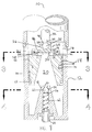
- Figure 1 is a partial section of such pump depicted at the top of its piston stroke.
- Figure 2 is a partial section of such pump depicted at the bottom of its piston stroke.
- Figure 3 depicts a section made along the line 3-3 of figure 1 in the direction indicated by the arrows.
- Figure 4 depicts a section made along the line 4-4 of figure 1 in the direction indicated by the arrows.
- FIG. 1 depicts a partial cross section of a preferred embodiment of a pump 10 submerged in a saturated liquid such as liquified natural gas (LNG).
- LNG liquified natural gas
- the pump 10 will be located within a high pressure cryogenic tank needed to keep the material in a liquid state.
- the pump 10 will be located within a cryogenic container needed to keep the material in a liquid state and with the cylinder submerged under the level of the liquid.
- the pump 10 discharge port described in greater detail below, will be associated with a transport line or distribution manifold to move the LNG to other tanks or to any other point of use. Since the configuration of such associated elements may vary, and no specific configuration is required, they are not depicted in the drawings.
- Pump 10 is a positive displacement reciprocating pump comprising a cylinder 12 and reciprocating piston 14.
- the piston 14 is depicted at the top of its stroke in Figure 1.
- a plurality of inlet openings 16 are evenly spaced around the upper circumference of the cylinder 12 to allow the liquid to flow into the cylinder above the piston 14.
- the piston 14 is a cylindrical block 18 having a hollow frusto-conical bore 20 (hereafter “conical bore” for brevity) oriented with its base at the bottom of the block 18 and tapering to open at the top where the block 18 is raised in a circular boss 22 to provide a sealing seat for an inlet valve means 24.
- conical bore hollow frusto-conical bore 20
- the valve means 24 comprises a cylindrical stem 26 with a circumferential disk 28 at its base to provide a flat sealing face 30 which, when seated against the boss 22, closes the conical bore 20 to liquid passage.
- the stem 26 is coupled to a push rod 32 by a ball coupling comprising a short rod extension 34 terminating in a ball 38.
- the stem 26 has a hollow chamber 40 with hemispherical bottom sides conforming to the dimensions of the ball 38, and an opening through which the rod extension 34 passes to connect to the push rod 32.
- the stem 26 and disk 28 are thus permitted to swivel around the ball 38 to seek a flat seating of its sealing face 30 against the boss 22.
- push rod 32 will be reciprocated by an appropriate engine and gearing to provide pumping power.
- the valve means 24 is operatively connected with the piston 14 by a cage 42 comprising multiple posts 44, each extending upward from the piston block 18 and having an inward facing flange 46 extending over the circumferential disk 28 of the valve stem 26.
- the cage 42 allows the valve disk 28 to open on the push rod upstroke with the piston remaining unmoved until the disk 28 engages the cage flanges 46; thereafter the piston is pulled up by the push rod to the top-of-stroke position depicted in Figure 1. In this position, liquid flowing into the cylinder through the inlet openings 16 passes around the cage posts 44 and through the conical bore 20 to fill the portion of the cylinder below the piston, as indicated by the directional arrows in Figure 1.
- the base of the cylinder 12 includes a frusto-conical valve housing 50 (hereafter "conical housing” for brevity) dimensioned to conform to the conical bore 20 such that, when the piston is at the bottom of its stroke, the conical housing 50 substantially fills the bore 20, as depicted in Figure 2.
- a discharge valve comprising an outlet channel 52 opening to a wider channel 56 by a tapered intermediate section 54 which acts as a seat for a ball valve 60.
- a spring 62 pushes the ball valve 60 against seat to close the outlet channel.
- the piston 14 also has conventional guide rings 66 and seal rings 68. If desired, a resilient "friction ring” 70, compatible with cryogenic service, can be provided which prevents the piston from sliding downward under its own weight before the valve disk "catches up” with the valve seat on the piston and builds up pressure in the pumping chamber.
- the described pump will have primary application in the cryogenic industry where the end use requires cryogenic liquids in low or moderate quantities but at a medium to very high pressures, and particularly where a net positive suction head is not available or difficult to attain, or where the pump is required to operate intermittently.
Landscapes
- Engineering & Computer Science (AREA)
- Mechanical Engineering (AREA)
- General Engineering & Computer Science (AREA)
- Reciprocating Pumps (AREA)
- Details Of Reciprocating Pumps (AREA)
Applications Claiming Priority (2)
| Application Number | Priority Date | Filing Date | Title |
|---|---|---|---|
| US07/728,461 US5188519A (en) | 1991-07-11 | 1991-07-11 | Saturated fluid pumping apparatus |
| US728461 | 1991-07-11 |
Publications (2)
| Publication Number | Publication Date |
|---|---|
| EP0523302A2 true EP0523302A2 (de) | 1993-01-20 |
| EP0523302A3 EP0523302A3 (en) | 1995-06-07 |
Family
ID=24926947
Family Applications (1)
| Application Number | Title | Priority Date | Filing Date |
|---|---|---|---|
| EP91308277A Withdrawn EP0523302A3 (en) | 1991-07-11 | 1991-09-11 | Saturated fluid pumping apparatus |
Country Status (5)
| Country | Link |
|---|---|
| US (1) | US5188519A (de) |
| EP (1) | EP0523302A3 (de) |
| JP (1) | JPH0518352A (de) |
| CA (1) | CA2049843C (de) |
| MX (1) | MX9101566A (de) |
Cited By (3)
| Publication number | Priority date | Publication date | Assignee | Title |
|---|---|---|---|---|
| EP1696124A1 (de) | 1999-04-22 | 2006-08-30 | Nvb International A/S | Kombination eines Zylinders und eines Kolbens |
| EP1750514A4 (de) * | 2004-01-22 | 2008-07-30 | Paul P Duron | Doppelwirkende, kryogene hochdruckpumpe |
| CH703376A1 (de) * | 2010-06-21 | 2011-12-30 | Fives Cryomec Ag | Hubkolbenpumpe für kryogene Flüssigkeiten. |
Families Citing this family (22)
| Publication number | Priority date | Publication date | Assignee | Title |
|---|---|---|---|---|
| SE470460B (sv) * | 1992-09-10 | 1994-04-18 | Electrolux Res & Innovation | Vakuumpump samt användning av densamma |
| JPH08144963A (ja) * | 1994-11-25 | 1996-06-04 | Nabco Ltd | 液化ガス用ポンプ装置 |
| US5511955A (en) * | 1995-02-07 | 1996-04-30 | Cryogenic Group, Inc. | Cryogenic pump |
| US5575626A (en) * | 1995-05-12 | 1996-11-19 | Cryogenic Group, Inc. | Cryogenic pump |
| US5810570A (en) * | 1997-01-06 | 1998-09-22 | Chemical Seal & Packing, Inc. | Super-low net positive suction head cryogenic reciprocating pump |
| US6006525A (en) * | 1997-06-20 | 1999-12-28 | Tyree, Jr.; Lewis | Very low NPSH cryogenic pump and mobile LNG station |
| FR2817848B1 (fr) * | 2000-12-12 | 2003-03-07 | Rexam Sofab | Micropompe electronique |
| US6530761B1 (en) * | 2001-04-04 | 2003-03-11 | Air Products And Chemicals, Inc. | Double-acting, two-stage pump |
| US6663350B2 (en) | 2001-11-26 | 2003-12-16 | Lewis Tyree, Jr. | Self generating lift cryogenic pump for mobile LNG fuel supply system |
| CA2362844C (en) * | 2001-11-30 | 2004-08-31 | Westport Research Inc. | Method and apparatus for delivering a high pressure gas from a cryogenic storage tank |
| JP3427383B1 (ja) * | 2002-04-08 | 2003-07-14 | 有限会社ケー・エム・シー | ピストンポンプ |
| US9341173B2 (en) | 2011-12-20 | 2016-05-17 | Lincoln Industrial Corporation | Lance pump with a ram |
| US9239044B2 (en) | 2012-03-19 | 2016-01-19 | Lincoln Industrial Corporation | Lance pump having horizontally mounted stepper/servo motor |
| US9140246B2 (en) | 2012-03-19 | 2015-09-22 | Lincoln Industrial Corporation | Lance pump having vertically mounted stepper motor |
| US9234452B2 (en) | 2012-05-17 | 2016-01-12 | Caterpillar Inc. | Direct injection gas engine and method |
| US20140169993A1 (en) * | 2012-12-18 | 2014-06-19 | Icecure Medical Ltd. | Cryogen pump |
| US9188069B2 (en) | 2012-12-27 | 2015-11-17 | Caterpillar Inc. | Gaseous fuel system, direct injection gas engine system, and method |
| US9926922B2 (en) * | 2015-01-30 | 2018-03-27 | Caterpillar Inc. | Barrel assembly for a fluid pump having separate plunger bore and outlet passage |
| US10036383B2 (en) | 2015-04-07 | 2018-07-31 | Caterpillar Inc. | Pump piston having variable diameter |
| CN109311385B (zh) | 2016-06-15 | 2022-04-08 | 沃尔沃卡车集团 | 气箱装置 |
| JP6106792B1 (ja) * | 2016-07-05 | 2017-04-05 | 三井造船株式会社 | 昇圧用ポンプ |
| EP3717042A4 (de) * | 2017-12-03 | 2021-09-08 | Carucell AB | Infusionspumpe |
Family Cites Families (11)
| Publication number | Priority date | Publication date | Assignee | Title |
|---|---|---|---|---|
| US1039757A (en) * | 1912-02-26 | 1912-10-01 | John C Kitton | Compressor. |
| US1357624A (en) * | 1918-01-02 | 1920-11-02 | Moon Brothers Mfg Company | Pump-piston |
| DE914861C (de) * | 1952-05-03 | 1954-09-27 | Adolf Messer G M B H | Hochdruckkolbenpumpe zur Foerderung verfluessigter Gase |
| US2815719A (en) * | 1954-01-08 | 1957-12-10 | Mustillo Nunzio | Pumps |
| US3335673A (en) * | 1966-01-17 | 1967-08-15 | Forrest Henry De | Manually operable pump |
| FR1478050A (fr) * | 1966-04-29 | 1967-04-21 | Pompe de déplacement positif, à mouvement alternatif notamment pour la manutention de liquides cryogéniques | |
| DE2628985A1 (de) * | 1976-06-28 | 1977-12-29 | Speck Kolbenpumpen Fabrik | Zylinder-kolbenanordnung fuer eine fluessigkeitspumpe |
| DE3149848A1 (de) * | 1981-12-16 | 1983-07-21 | Linde Ag, 6200 Wiesbaden | "kolbenpumpe fuer verfluessigte gase" |
| WO1987002100A1 (en) * | 1984-03-27 | 1987-04-09 | Axel Egnell | Displacement pump |
| DE3621727A1 (de) * | 1986-06-28 | 1988-01-14 | Deutsche Forsch Luft Raumfahrt | Kolbenpumpe fuer kryogene fluessigkeiten |
| FR2630785B1 (fr) * | 1988-05-02 | 1994-02-04 | Institut Francais Petrole | Dispositif de pompage polyphasique a piston et applications de ce dispositif |
-
1991
- 1991-07-11 US US07/728,461 patent/US5188519A/en not_active Expired - Lifetime
- 1991-08-26 CA CA002049843A patent/CA2049843C/en not_active Expired - Fee Related
- 1991-09-11 EP EP91308277A patent/EP0523302A3/en not_active Withdrawn
- 1991-09-13 JP JP3261407A patent/JPH0518352A/ja not_active Withdrawn
- 1991-10-11 MX MX9101566A patent/MX9101566A/es not_active IP Right Cessation
Cited By (5)
| Publication number | Priority date | Publication date | Assignee | Title |
|---|---|---|---|---|
| EP1696124A1 (de) | 1999-04-22 | 2006-08-30 | Nvb International A/S | Kombination eines Zylinders und eines Kolbens |
| CN101498299A (zh) * | 1999-04-22 | 2009-08-05 | Nvb国际公司 | 活塞和腔室的组合及包括该组合的泵、吸震器和促动器 |
| CN101498299B (zh) * | 1999-04-22 | 2013-12-11 | Nvb国际公司 | 活塞和腔室的组合及包括该组合的泵、吸震器和促动器 |
| EP1750514A4 (de) * | 2004-01-22 | 2008-07-30 | Paul P Duron | Doppelwirkende, kryogene hochdruckpumpe |
| CH703376A1 (de) * | 2010-06-21 | 2011-12-30 | Fives Cryomec Ag | Hubkolbenpumpe für kryogene Flüssigkeiten. |
Also Published As
| Publication number | Publication date |
|---|---|
| JPH0518352A (ja) | 1993-01-26 |
| CA2049843C (en) | 1997-09-30 |
| CA2049843A1 (en) | 1993-01-12 |
| MX9101566A (es) | 1993-01-01 |
| US5188519A (en) | 1993-02-23 |
| EP0523302A3 (en) | 1995-06-07 |
Similar Documents
| Publication | Publication Date | Title |
|---|---|---|
| US5188519A (en) | Saturated fluid pumping apparatus | |
| US12188461B2 (en) | Compression apparatus and filling station comprising such an apparatus | |
| US12092098B2 (en) | Compression apparatus and filling station comprising such an apparatus | |
| US20170227002A1 (en) | Cryogenic pump and inlet header | |
| JPS6336068A (ja) | 極低温流体用ピストンポンプ | |
| US4156584A (en) | Liquid cryogen pump | |
| US4239463A (en) | Reciprocating plunger pump with improved liquid end valve assembly | |
| CN115023549A (zh) | 压缩设备和包括这种设备的充装站 | |
| US5314025A (en) | Fluid pumping apparatus and method of pumping fluid | |
| US5810570A (en) | Super-low net positive suction head cryogenic reciprocating pump | |
| US4249868A (en) | Pump for high viscosity lubricants with improved priming feature | |
| US4591316A (en) | Piston with simple retention valve | |
| US7610930B2 (en) | Discharge valve for downhole pumps | |
| US3074352A (en) | Well pump | |
| US4591315A (en) | Piston with composite retention valve | |
| NL9101691A (nl) | Zelfbedienend inlaatklepsamenstel voor inzetpompen met heen- en weergaande beweging die ondergronds kunnen worden gebracht. | |
| US1832346A (en) | Traveling tube pump | |
| US12553421B2 (en) | Fluid compression apparatus and method | |
| US39974A (en) | Improvement in pumps | |
| US333808A (en) | Double-acting pump | |
| US388943A (en) | John woodwabd and eobeet anderson | |
| US591382A (en) | Apparatus for pumping water | |
| US3314372A (en) | Pump | |
| US443496A (en) | Portable siphon | |
| US394088A (en) | tylee |
Legal Events
| Date | Code | Title | Description |
|---|---|---|---|
| PUAI | Public reference made under article 153(3) epc to a published international application that has entered the european phase |
Free format text: ORIGINAL CODE: 0009012 |
|
| AK | Designated contracting states |
Kind code of ref document: A2 Designated state(s): DE ES FR GB IT NL SE |
|
| PUAL | Search report despatched |
Free format text: ORIGINAL CODE: 0009013 |
|
| AK | Designated contracting states |
Kind code of ref document: A3 Designated state(s): DE ES FR GB IT NL SE |
|
| STAA | Information on the status of an ep patent application or granted ep patent |
Free format text: STATUS: THE APPLICATION IS DEEMED TO BE WITHDRAWN |
|
| 18D | Application deemed to be withdrawn |
Effective date: 19951208 |