EP0523400A2 - Zusammenschiebbares Verdeck für Fahrzeuge oder Fahrzeugaufbauten - Google Patents
Zusammenschiebbares Verdeck für Fahrzeuge oder Fahrzeugaufbauten Download PDFInfo
- Publication number
- EP0523400A2 EP0523400A2 EP92110481A EP92110481A EP0523400A2 EP 0523400 A2 EP0523400 A2 EP 0523400A2 EP 92110481 A EP92110481 A EP 92110481A EP 92110481 A EP92110481 A EP 92110481A EP 0523400 A2 EP0523400 A2 EP 0523400A2
- Authority
- EP
- European Patent Office
- Prior art keywords
- support struts
- roller
- roller carriage
- hood according
- support
- Prior art date
- Legal status (The legal status is an assumption and is not a legal conclusion. Google has not performed a legal analysis and makes no representation as to the accuracy of the status listed.)
- Granted
Links
Images

Classifications
-
- B—PERFORMING OPERATIONS; TRANSPORTING
- B60—VEHICLES IN GENERAL
- B60J—WINDOWS, WINDSCREENS, NON-FIXED ROOFS, DOORS, OR SIMILAR DEVICES FOR VEHICLES; REMOVABLE EXTERNAL PROTECTIVE COVERINGS SPECIALLY ADAPTED FOR VEHICLES
- B60J7/00—Non-fixed roofs; Roofs with movable panels, e.g. rotary sunroofs
- B60J7/02—Non-fixed roofs; Roofs with movable panels, e.g. rotary sunroofs of sliding type, e.g. comprising guide shoes
- B60J7/06—Non-fixed roofs; Roofs with movable panels, e.g. rotary sunroofs of sliding type, e.g. comprising guide shoes with non-rigid element or elements
- B60J7/061—Non-fixed roofs; Roofs with movable panels, e.g. rotary sunroofs of sliding type, e.g. comprising guide shoes with non-rigid element or elements sliding and folding
- B60J7/064—Non-fixed roofs; Roofs with movable panels, e.g. rotary sunroofs of sliding type, e.g. comprising guide shoes with non-rigid element or elements sliding and folding using folding arms sliding in longitudinal tracks for supporting the soft roof
- B60J7/065—Non-fixed roofs; Roofs with movable panels, e.g. rotary sunroofs of sliding type, e.g. comprising guide shoes with non-rigid element or elements sliding and folding using folding arms sliding in longitudinal tracks for supporting the soft roof for utility vehicles
Definitions
- the innovation relates to a collapsible convertible top for vehicles or vehicle bodies or containers, consisting of two rails extending over the length of the vehicle platform or the vehicle body and a large number of longitudinally displaceable and height-adjustable supports supporting a convertible top tarpaulin by means of roller carriages and support struts, whereby the support struts are each grouped in pairs and are articulated to one another and each carry a bow in pairs and the articulated support struts of each pair are in an at least approximately extended position when the top is closed.
- Collapsible tops of the type identified above are known for trucks and trailers or vehicle bodies or containers, and serve to simplify and facilitate opening of the top for loading the vehicle or container from above. Since on the one hand the maximum permissible total height of vehicle superstructures or containers is essentially dictated on the one hand by regulations and on the other hand by existing passages and the like, more or less unchangeable circumstances, but on the other hand within the maximum total height of the vehicle or container the greatest possible usable internal height of the transport space must be aimed for, the lowest possible construction of the convertible top located in its closed position.
- the innovation is therefore based on the technical task of improving a collapsible convertible top of the type described in such a way that the advantage of an extremely low construction of the closed convertible top is achieved without disadvantageous its adjustability, and overall the effort is kept as low as possible for the manufacture of the top.
- a simplification of essential components of the convertible top is to be made possible at the same time.
- this object is essentially achieved in that the support struts are articulated on the side cheeks of the roller carriages which surround the guide rails and are parallel to these.
- the articulation of the support struts on the side cheeks of the roller carriages enables the articulation points of the support struts to be arranged below the upper surface plane of the guide rail profile in such a way that, when the top is closed, on the one hand the bows carried by the support struts rest on the upper surface of the guide rail profile and the two form a pair proper support struts can still assume a mutual angular position ensuring the folding and setting up of the strut pairs.
- a substantial simplification of the design of the roller carriages is possible, which can now be formed by a simple U-shaped pressed sheet metal part or a section of a U-profile.
- the articulation axes of the support struts with the roller axles of the roller carriages in a common plane or below the level of the plane running through roller axes of the roller carriages can be arranged.
- the support struts of each pair are alternately connected to the inner and outer side cheeks of a roller carriage, with the articulations of the support struts on the side cheeks or the extensions of the side cheeks of the roller carriages using bolts for the sake of being as narrow as possible Countersunk head are formed and the screw bolts with their countersunk head lie in a countersink provided on the inside of the side cheeks or their extensions.
- the support struts of each pair are connected to one, in particular the inner side wall of a roller carriage, the two support struts abutting one another by means of a washer, preferably made of a bearing material, and one of the two support struts hinged next to one another is cranked out laterally above its articulation.
- the support struts are mounted on the side cheeks of the roller carriages by means of a flat-headed collar screw bolt.
- the innovation further provides that the articulated connections of the two support struts belonging to a pair are formed by a screw bolt spanning the width of the roller carriages and a surrounding, possibly two-part spacer sleeve.
- a roller is switched on in the articulated connection of the two supporting struts of a pair, which is on the upper one when the convertible top is in the closed position Surface of the track profile rests.
- the roller is expediently supported on the one hand against a spacer sleeve surrounding the screw bolt and on the other hand by means of a number of disks against the inner side surface of the one support strut.
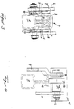
- the loading platform of a truck not shown in detail in the drawing, or the top opening of a vehicle body or a container are spanned over their length by a pair of guide rails 1 arranged along their two long sides.
- the guide rails 1 each have a cross-sectionally I-shaped guide profile placed on a box-shaped support profile.
- longitudinally movable roller carriages 2 are guided, which have an essentially U-shaped roller carriage chassis 3 and two pairs of rollers 4, the rollers 4 each being rotatable in pairs about a roller axis 5 and being mounted opposite one another on the roller carriage side walls 6.
- two support struts 7 and 8 are each pivoted about an axis 7 parallel to the roller axes 5. At the other end, the two are connected to one another in a hinged manner to form a pair of supporting struts 7 and 8.
- the two support struts 7 and 8 are articulated alternately on the inside and outside of the roller carriage 2 with respect to the longitudinal center of the vehicle, the side walls 6 of the roller carriage 2 being extended downward by means of an attached tab 9 and the support struts 7 and 8 in each case are articulated to the straps 9 by means of a bearing pin formed by a countersunk screw 10.
- the countersunk screws 10 are Corresponding countersinks 11 are assigned in the tabs 9 in order to achieve a narrow construction of the bearings of the support struts 7 and 8.
- a support strut 7 which is articulated on the inside of a roller carriage 2 is articulated by means of a screw bolt 12 spanning the width of the roller carriage 2 with a support strut 8 which is articulated on the outside of the other or following roller carriage.
- the bolt 12 forming the articulated connection between the two support struts 7 and 8 is accommodated according to the embodiment according to FIG. 2 in a two-part spacer sleeve 14 securing the distance between the two support struts 7 and 8.
- FIG. 1 the embodiment according to FIG.
- a support 15 is formed by cutting an angle profile for a bow formed by a square profile material connected, the length of which is dimensioned such that it bridges the distance between the two support struts 7 and 8 and still projects beyond them on both sides.
- the embodiment according to FIG. 4 provides that a roller 16 is switched on in the articulated connection of the two supporting struts 7 and 8, which complement one another and which, when the convertible top is closed, on the upper surface of the guide rail 1 lies on.
- the roller 16 lies on the one hand against one part 17 of a spacer sleeve and on the other hand against a package of disks 18 and is mounted on the screw bolt 12 as a whole.
- the support struts 7 and 8 of each pair are connected to one, in particular the inner side wall 6 of a roller carriage 2, the two support struts 7 and 8 abutting one another by means of a washer 22 and the inner of the two lying side by side articulated support struts 7 and 8 laterally cranked above their articulation is.
- the support struts 7 and 8 are supported by means of collar bushings 20 made of a maintenance-free bearing material on which they are mounted on screw bolts bearing on the side walls 6 of the roller carriages 2, with the bearing axles of the support struts 7 and 8 being in this embodiment are formed by a flat head 24 collar bolts 21 which are screwed into the side walls 6 of the roller carriage 2.
Landscapes
- Engineering & Computer Science (AREA)
- Mechanical Engineering (AREA)
- Tents Or Canopies (AREA)
- Body Structure For Vehicles (AREA)
- Fittings On The Vehicle Exterior For Carrying Loads, And Devices For Holding Or Mounting Articles (AREA)
- Superstructure Of Vehicle (AREA)
Abstract
Description
- Die Neuerung bezieht sich auf ein zusammenschiebbares Verdeck für Fahrzeuge oder Fahrzeugaufbauten bzw. Container, bestehend aus zwei sich über die Länge der Fahrzeugpritsche oder des Fahrzeugaufbaues hin erstreckenden Laufschienen und einer Vielzahl an diesen vermittels Rollenwagen und Stützstreben längsveschiebbar und höhenveränderlich abgestützter eine Verdeckplane unterstützenden Spriegeln, wobei die Stützstreben jeweils paarweise zu Gruppen zusammengefasst und gelenkig untereinander verbunden sind sowie jeweils paarweise einen Spriegel tragen und wobei sich die gelenkig miteinander verbundenen Stützstreben jedes Paares bei geschlossenem Verdeck in einer wenigstens annähernden Strecklage befinden.
- Zusammenschiebbare Verdecke der vorstehend gekennzeichneten Bauart sind für Lastkraftwagen und Anhänger bzw. Fahrzeugaufbauten oder Container bekannt, und dienen dazu ein Öffnen des Verdeckes für die Beladung des Fahrzeuges oder Containers von oben her zu vereinfachen und zu erleichtern. Da auf der einen Seite die maximal zulässige Gesamthöhe von Fahrzeugaufbauten oder Containern im wesentlichen zum einen durch Vorschriften und zum anderen durch vorhandene Durchfahrten und dergl. mehr oder minder unabänderliche Gegebenheiten vorgezeichnet ist, auf der anderen Seite aber innerhalb der maximalen Gesamthöhe des Fahrzeuges bzw. Containers eine möglichst große nutzbare Innenhöhe des Transportraumes angestrebt werden muß ist eine möglichst niedrig bauende Ausbildung des in seinr Schließlage befindlichen Verdeckes anzustreben.
- Der Neuerung liegt daher die technische Aufgabe zugrunde ein zusamnmenschiebbares Verdeck der eingangs bezeichneten Bauart dahingehend zu verbessern, daß der Vorteil einer extrem niedrigen Bauweise des geschlosenen Verdeckes ohne nachteilige seiner Verstellbarkeit erreicht und dabei insgesamt der Aufwand für die Herstellung des Verdeckes möglichst gering gehalten wird. Darüberhinaus soll gleichzeitig auch eine Vereinfachung wesentlicher Bauelemente des Verdeckes ermöglicht werden.
- Diese Aufgabe wird neuerungsgemäß im wesentlichen dadurch gelöst, daß die Stützstreben an den die Führungsschienen umgreifenden und zu diesen parallelen Seitenwangen der Rollenwagen angelenkt sind. Die Anlenkung der Stützstreben an den Seitenwangen der Rollenwagen ermöglicht es die Anlenkstellen der Stützstreben unterhalb der oberen Oberflächenebene des Führungsschienenprofiles anzuordnen, derart, daß bei geschlossenem Verdeck zum einen die von den Stützstreben getragenen Spriegel auf der oberen Oberfläche des Führungsschienenprofiles aufliegen und die beiden zu einem Paar gehörigen Stützstreben trotzdem eine das Falten und Aufstellen der Strebenpaare gewährleistende gegenseitige Winkelstellung einnehmen können. In Verbindung damit wird gleichzeitig auch eine wesentliche Vereinfachung der Ausbildung der Rollenwagen möglich, die nunmehr durch ein einfaches U-förmiges Blechpressteil oder einen Abschnitt eines U-Profiles gebildet sein können.
- Je nach Auslegung des Verdeckes und insbesondere dessen Führungsschienen bzw. der Steghöhe des die Stützstreben bildenden Flachmaterials kommen verschiedene Höhenlagen der Anlenkachsen der Stützstreben an den Seitenwangen der Rollenwagen in Betracht, wobei die Anlenkachsen der Stützstreben mit den Rollenachsen der Rollenwagen in einer gemeinsamen Ebene oder aber unterhalb der Ebene der durch Rollenachsen der Rollenwagen verlaufenden Ebene angeordnet sein können. Für die bevorzugterweise zur Anwendug kommende Anordnung der Anlenkachse unterhalb der durch die Rollenachsen laufenden Ebene ist dann weiter vorgesehen, daß entweder die Seitenwangen der Rollenwagen über die Aufstandsebene der Rollen der Rollenwagen an den Führungsschienen hinaus nach unten verlängert sind, wobei die über die Aufstandsebene der Rollen der Rollenwagen an den Führungsschienen hinaus nach unten gerichteten Verlängerungen mit den Seitenwangen der Rollenwagen einteilig ausgebildet sind, oder aber, was sich besonders bei in kleineren Stückzahlen zu fertigenden Verdecken empfiehlt, die über die Aufstandsebene der Rollen der Rollenwagen an den Führungsschienen hinaus nach unten reichenden Verlängerungen der Seitenwangen der Rollenwagen durch auf diese aufgesetzte Traglaschen oder dergl. Formstücke gebildet sind.
- In bevorzugter Ausgestaltung der Neuerung ist weiter vorgesehen, daß die Stützstreben jedes Paares wechselseitig an die innere und äußere Seitenwange jeweils eines Rollenwagens angeschlossen sind, wobei zwecks möglichst schmalbauender Ausführung die Anlenkungen der Stützstreben an den Seitenwangen bzw. den Verlängerungen der Seitenwangen der Rollenwagen durch Schraubenbolzen mit Senkkopf gebildet sind und die Schraubenbolzen mit ihrem Senkkopf in einer an der der Innenseite der Seitenwangen bzw. deren Verlängerungen vorgesehenen Ansenkung einliegen.
In einer abgewandelten Ausführungsform kann jedoch auch vorgesehen sein, daß die Stützstreben jedes Paares an einer, insbesondere der inneren Seitenwange jeweils eines Rollenwagens angeschlossen sind, wobei die beiden Stützstreben vermittels einer Beilagscheibe, vorzugsweise aus einem Lagermaterial, aneinander anliegen und eine der beiden nebeneinanderliegend angelenkten Stützstreben oberhalb ihrer Anlenklagerung seitlich ausgekröpft ist. - Ferner kann bezüglich der Gestaltung der Lagerachsen für die Stützstreben wahlweise auch vorgesehen sein, daß die Stützstreben vermittels einen Flachkopf aufweisender Bund-Schraubenbolzen an den Seitenwangen der Rollenwagen gelagert sind.
- Für die Ausbildung der Lagerung der Stützstreben an den Rollenwagen kann unabhängig von der Einzelausgestaltung der Anlenlagerung vorgesehen sein, daß die Stützstreben vermittels Bundbuchsen auf den sie an den Seitenwangen der Rollenwagen lagernden Schraubenbolzen belagert sind.
- Bei einer wechselseitig innen und außenliegender Anlenkung der Stützstreben an den Rollenwagen ist neuerungsgemäß weiter vorgesehen, daß die gelenkigen Verbindungen der beiden zu einem Paar gehörigen Stützstreben durch einen die Breite der Rollenwagen überspannenden Schraubenbolzen und eine diesen umgebende, gegebenenfalls zweiteilige Distanzhülse gebildet sind. In Verbindung mit einer solchen Ausbildung der glenkigen Verbindung zweier einander zu einem Paar ergänzender Stützstreben kann nach einer vorteilhaften weiteren Ausgestaltung vorgesehen sein, daß in die gelenkige Verbindung der beiden Stützstreben eines Paares eine Rolle eingeschaltet ist, die bei in der Schließlage befindlichem Verdeck auf der oberen Oberfläche des Laufschienenprofiles aufliegt. Die Rolle ist dabei zweckmäßigerweise einerseits gegen eine den Schraubenbolzen umgebende Distanzhülse und andererseits vermittels einer Anzahl von Scheiben gegen die innenliegende Seitenfläche der einen Stützstrebe abgestützt.
- Schließlich wird noch ein Merkmal der Neuerung darin gesehen, daß die an der einen, insbesondere der jeweils innenliegenden Stützstrebe eines Paares befestigte, insbesondere durch Winkelprofilabschnitte gebildete :Auflager für die Spriegel den Abstand zwischen den wechselseitig innen-und außenliegend an den Rollenwagen angelenkten Stützstreben übergreifen.
- Die Neuerung ist in der nachfolgenden beispielsbeschreibung anhand eines in der Zeichnung dargestellten .Ausführungsbeispieles im Einzelnen beschrieben. In der Zeichung zeigt die
- Figur 1 eine Ausschnittweise Seitenansicht eines zusammenschiebbaren Verdeckes;
- Figur 2 eine Drautsicht zu Figur 1;
- Figur 3 einen Teilschnitt durch das Verdeck entlang der Linie III-III in Figur 2;
- Figur 4 einen Teilschnitt durch das Verdeck entlang der Linie IV-IV in Figur 2;
- Figur 5 einen Teilschnitt entsprechend Figur 3 durch eine andere Ausführungsform;
- Figur 6 einen Teilschnitt entsprechend Figur 3 durch eine weitere Ausführungsform.
- Die in der Zeichnung nicht im einzelnen dargestellte Ladepritsche eines Lastkraftwagens bzw. die oberseitige Öffnung eines Fahrzeugaufbaues oder eines Containers sind über ihre Länge hin von einem Paar entlang ihrer beiden Längsseiten angeordneter Führungsschienen 1 überspannt. Die Führungsschienen 1 weisen, wie insbesondere aus den Darstellungen der Figuren 3 und 4 ersichtlich, jeweils ein auf ein kastenförmiges Tragprofil aufgesetztes im Querschnitt I-förmiges Führungsprofil auf. An den Führungsschienen 1 sind längsverfahrbar Rollenwagen 2 geführt, welche ein im wesentlichen U-förmiges Rollenwagenchassis 3 und zwei Paare von Laufrollen 4 aufweisen, wobei die Laufrollen 4 jeweils paarweise um eine Rollenachse 5 drehbar und einander gegenüberliegend an den Rollenwagenseitenwangen 6 gelagert sind. An jedem Rollenwagen 2 sind jeweils zwei Stützstreben 7 und 8 um eine zu den Rollenachsen 5 parallele Achse 7 schwenkbar angelenkt. An ihrem anderen Ende sind die beiden einander jeweils zu einem Paar ergänzenden Stützstreben 7 und 8 gelenkig untereinander verbunden.
Bei dem in der Zeichnung dargestellten Ausführungsbeispiel sind die beiden Stützstreben 7 und 8 bezüglich der Fahrzeuglängsmitte jeweils wechselseitig innen- und außenliegend am Rollenwagen 2 angelenkt, wobei die Seitenwangen 6 der Rollenwagen 2 vermittels einer aufgesetzten Lasche 9 nach unten verlängert und die Stützstreben 7 und 8 jeweils vermittels eines durch eine Senkkopfschraube 10 gebildeten Lagerzapfens an den Laschen 9 angelenkt sind. Den Senkkopfschrauben 10 sind entsprechende Ansenkungen 11 in den Laschen 9 zugeordnet, um eine schmalbauende Gestaltung der Lagerungen der Stützstreben 7 und 8 zu erreichen. Dabei ist, wie insbesondere aus der Figur 2 ersichtlich, jeweils eine innenliegend am einen Rollenwagen 2 angelenkte Stützstrebe 7 mittels eines die Breite der Rollenwagen 2 überspannenden Schraubenbolzens 12 gelenkig mit einer am anderen bzw. folgenden Rollenwagen außenseitig angelenkten Stützstrebe 8 verbunden. Der die Gelenkverbindung zwischen den beiden Stützstreben 7 und 8 bildende Schraubenbolzen 12 ist gemäß der Ausführungsform nach Figur 2 in einer zweiteilig ausgebildeten, den Abstand zwischen den beiden Stützstreben 7 und 8 sichernden Distanzhülse 14 aufgenommen. Ferner ist bei der Ausführungsform nach Figur 2 an das freie, die durch den Schraubenbolzen 12 gebildete Gelenkverbindung der beiden Stützstreben 7 und 8 überragende Ende der innenliegend angelenkten Stützstrebe 7 ein durch einen Zuschnitt eines Winkelprofiles gebildetes Auflager 15 für einen durch ein Vierkant-Profilmaterial gebildeten Spriegel angeschlosen, dessen Länge so bemessen ist, daß es den Abstand zwischen den beiden Stützstreben 7 und 8 überbrückt und diese beidseitig noch überragt. Abweichend von dem in der Figur 2 gezeigten Ausführungsbeispiel ist bei der Ausführungsform nach Figur 4 vorgesehen, daß in die Gelenkverbindung der beiden einander zu einem Paar ergänzenden Stützstreben 7 und 8 eine Rolle 16 eingeschaltet ist, welche bei geschlossenem Verdeck auf der oberen Oberfläche der Führungsschiene 1 aufliegt. Die Rolle 16 liegt dabe einerseits gegen den einen Teil 17 einer Distanzhülse und andererseits gegen ein Paket von Scheiben 18 an und ist insgesamt auf dem Schraubenbolzen 12 gelagert. - Bei der in der Figur 5 dargestellten abgewandelten Ausführungsform sind die Stützstreben 7 und 8 jedes Paares an einer, insbesondere der inneren Seitenwange 6 jeweils eines Rollenwagens 2 angeschlossen, wobei die beiden Stützstreben 7 und 8 vermittels einer Belagscheibe 22 aneinander anliegen und die innere der beiden nebeneinanderliegend angelenkten Stützstreben 7 und 8 oberhalb ihrer Anlenklagerung seitlich ausgekröpft ist.
- Aus der in der Figur 6 dargestellten Ausführungsform ist ersichtlich, daß die Stützstreben 7 und 8 vermittels Bundbuchsen 20 aus einem wartungsfreien Lagermaterial auf den sie an den Seitenwangen 6 der Rollenwagen 2 lagernden Schraubenbolzen gelagert sind, wobei bei dieser Ausführungsform die Lagerachsen der Stützstreben 7 und 8 durch einen Flachkopf 24 aufweisende Bund-Schraubenbolzen 21, die in die Seitenwangen 6 der Rollenwagen 2 eingeschraubt sind, gebildet sind.
Claims (16)
Applications Claiming Priority (2)
| Application Number | Priority Date | Filing Date | Title |
|---|---|---|---|
| DE9108115U | 1991-07-02 | ||
| DE9108115U DE9108115U1 (de) | 1991-07-02 | 1991-07-02 | Zusammenschiebbares Verdeck für Fahrzeuge oder Fahrzeugaufbauten |
Publications (3)
| Publication Number | Publication Date |
|---|---|
| EP0523400A2 true EP0523400A2 (de) | 1993-01-20 |
| EP0523400A3 EP0523400A3 (de) | 1993-02-03 |
| EP0523400B1 EP0523400B1 (de) | 1995-10-18 |
Family
ID=6868868
Family Applications (1)
| Application Number | Title | Priority Date | Filing Date |
|---|---|---|---|
| EP92110481A Expired - Lifetime EP0523400B1 (de) | 1991-07-02 | 1992-06-22 | Zusammenschiebbares Verdeck für Fahrzeuge oder Fahrzeugaufbauten |
Country Status (6)
| Country | Link |
|---|---|
| EP (1) | EP0523400B1 (de) |
| AT (1) | ATE129206T1 (de) |
| CZ (1) | CZ278852B6 (de) |
| DE (2) | DE9108115U1 (de) |
| ES (1) | ES2079103T3 (de) |
| SK (1) | SK207692A3 (de) |
Cited By (2)
| Publication number | Priority date | Publication date | Assignee | Title |
|---|---|---|---|---|
| AU699788B2 (en) * | 1995-08-17 | 1998-12-17 | George Peter Formosa | Vehicle load cover |
| EP1205325A1 (de) * | 2000-11-11 | 2002-05-15 | Trailer System Engineering GmbH & Co. KG | Faltverdeckanordnung für Fahrzeugaufbauten |
Families Citing this family (5)
| Publication number | Priority date | Publication date | Assignee | Title |
|---|---|---|---|---|
| DE9309466U1 (de) * | 1993-01-30 | 1993-09-30 | Waggonfabrik Talbot, 52070 Aachen | Eisenbahngüterwagen |
| BE1019433A5 (nl) | 2010-07-23 | 2012-07-03 | Vbg Group Truck Equipment N V | Constructie voor een schuifdak, schuifdaksysteem, vrachtwagen met schuifdaksysteem, schuifzeiltrailer met een schuifdaksysteem. |
| DE102014013789B4 (de) * | 2014-09-23 | 2019-09-12 | European Trailer Systems Gmbh | Verdeckgestell für eine zusammenschiebbare Plane |
| DE102014013787B4 (de) * | 2014-09-23 | 2019-06-19 | European Trailer Systems Gmbh | Verdeckgestell für eine zusammenschiebbare Plane |
| DE102014013788B4 (de) * | 2014-09-23 | 2019-06-19 | European Trailer Systems Gmbh | Verdeckgestell für eine zusammenschiebbare Plane |
Family Cites Families (2)
| Publication number | Priority date | Publication date | Assignee | Title |
|---|---|---|---|---|
| DE1956392C3 (de) * | 1969-11-10 | 1978-11-30 | Ed. Scharwaechter Gmbh + Co Kg, 5630 Remscheid | Zusammenschiebbares Verdeck, insbesondere für Lastkraftwagen und -anhänger |
| ATE16370T1 (de) * | 1981-07-06 | 1985-11-15 | Kaessbohrer Fahrzeug Karl | Transportmulde mit einem schiebeverdeck. |
-
1991
- 1991-07-02 DE DE9108115U patent/DE9108115U1/de not_active Expired - Lifetime
-
1992
- 1992-06-22 AT AT92110481T patent/ATE129206T1/de not_active IP Right Cessation
- 1992-06-22 ES ES92110481T patent/ES2079103T3/es not_active Expired - Lifetime
- 1992-06-22 DE DE59204044T patent/DE59204044D1/de not_active Expired - Fee Related
- 1992-06-22 EP EP92110481A patent/EP0523400B1/de not_active Expired - Lifetime
- 1992-07-02 CZ CS922076A patent/CZ278852B6/cs not_active IP Right Cessation
- 1992-07-02 SK SK2076-92A patent/SK207692A3/sk unknown
Cited By (2)
| Publication number | Priority date | Publication date | Assignee | Title |
|---|---|---|---|---|
| AU699788B2 (en) * | 1995-08-17 | 1998-12-17 | George Peter Formosa | Vehicle load cover |
| EP1205325A1 (de) * | 2000-11-11 | 2002-05-15 | Trailer System Engineering GmbH & Co. KG | Faltverdeckanordnung für Fahrzeugaufbauten |
Also Published As
| Publication number | Publication date |
|---|---|
| DE9108115U1 (de) | 1992-10-29 |
| ATE129206T1 (de) | 1995-11-15 |
| EP0523400A3 (de) | 1993-02-03 |
| ES2079103T3 (es) | 1996-01-01 |
| SK279929B6 (sk) | 1999-05-07 |
| CZ278852B6 (en) | 1994-07-13 |
| SK207692A3 (en) | 1999-05-07 |
| CZ207692A3 (en) | 1993-01-13 |
| EP0523400B1 (de) | 1995-10-18 |
| DE59204044D1 (de) | 1995-11-23 |
Similar Documents
| Publication | Publication Date | Title |
|---|---|---|
| EP0733003B1 (de) | Fahrzeug mit einem aufbau | |
| DE2923428A1 (de) | Transportabler container fuer den transport von personenkraftwagen | |
| DE69016336T2 (de) | Faltbares Verdeck für eine Ladefläche. | |
| DE19842844C1 (de) | Mechanische Vorrichtung zum Heben eines auf Eckrungen ruhenden Dachs eines Nutzfahrzeugaufbaus | |
| EP0523400B1 (de) | Zusammenschiebbares Verdeck für Fahrzeuge oder Fahrzeugaufbauten | |
| DE9014816U1 (de) | Bahnwaggon mit anheb- und absenkbarem Ladeplatz, insbesondere für den Transport von Straßenfahrzeugen wie Lastkraftwagen u.ä. | |
| WO2020177809A1 (de) | Untergestell eines schienenfahrzeuges | |
| EP0609655B1 (de) | Eisenbahngüterwagen | |
| DE3418060C2 (de) | Zusammenschiebbares Verdeck, insbes. für Lastkraftwagen und Anhänger | |
| EP2676824A2 (de) | Aufbau zum Befördern von Gütern | |
| DE4341906A1 (de) | Nutzfahrzeug, insb. Getränkefahrzeug, mit tiefliegender und absenkbarer Ladepritsche | |
| DE2509166C3 (de) | Fahrzeug-Transportwagen | |
| DE1956392C3 (de) | Zusammenschiebbares Verdeck, insbesondere für Lastkraftwagen und -anhänger | |
| DE3307261A1 (de) | Lasthandhabungsgeraet | |
| EP1120324B1 (de) | Planendach für Eisenbahnwagen oder andere Transport- oder Lagereinrichtungen mit auf Laufwagen geführten Spriegeln | |
| DE68902661T2 (de) | Eisenbahnwagen zum transport von platten auf boecken. | |
| EP0614792A1 (de) | Aussenlangträger für 2achsige Eisenbahngüterwagen | |
| DE4325006C2 (de) | Verfahrbare Schrägrampe | |
| DE9200417U1 (de) | Flachbauendes, zusammenschiebbares Verdeck für Fahrzeuge, Fahrzeugaufbauten oder Container u.dgl. | |
| EP0903276A2 (de) | Schlepper für ein verfahrbares Ladegestell | |
| DE2936662A1 (de) | Nutzfahrzeug, bei dem zumindest eine wand des ladeflaechenaufbaus eine planenabdeckung aufweist | |
| DE68902225T2 (de) | Fahrzeug mit verschiebbaren seitenschliesselementen. | |
| DE19512020A1 (de) | Eisenbahngüterwagen, insbesondere Containertragwagen | |
| DE29518266U1 (de) | Hubfahrzeug zum Anheben, Transportieren und Absenken von Transportgut | |
| DE19959673C2 (de) | Fahrzeuganhänger |
Legal Events
| Date | Code | Title | Description |
|---|---|---|---|
| PUAI | Public reference made under article 153(3) epc to a published international application that has entered the european phase |
Free format text: ORIGINAL CODE: 0009012 |
|
| PUAL | Search report despatched |
Free format text: ORIGINAL CODE: 0009013 |
|
| 17P | Request for examination filed |
Effective date: 19920622 |
|
| AK | Designated contracting states |
Kind code of ref document: A2 Designated state(s): AT BE CH DE ES FR GB IT LI NL |
|
| RAP1 | Party data changed (applicant data changed or rights of an application transferred) |
Owner name: ED. SCHARWAECHTER GMBH & CO. FAHRZEUGTECHNIK |
|
| AK | Designated contracting states |
Kind code of ref document: A3 Designated state(s): AT BE CH DE ES FR GB IT LI NL |
|
| 17Q | First examination report despatched |
Effective date: 19940920 |
|
| GRAA | (expected) grant |
Free format text: ORIGINAL CODE: 0009210 |
|
| AK | Designated contracting states |
Kind code of ref document: B1 Designated state(s): AT BE CH DE ES FR GB IT LI NL |
|
| REF | Corresponds to: |
Ref document number: 129206 Country of ref document: AT Date of ref document: 19951115 Kind code of ref document: T |
|
| ET | Fr: translation filed | ||
| GBT | Gb: translation of ep patent filed (gb section 77(6)(a)/1977) |
Effective date: 19951024 |
|
| REF | Corresponds to: |
Ref document number: 59204044 Country of ref document: DE Date of ref document: 19951123 |
|
| REG | Reference to a national code |
Ref country code: ES Ref legal event code: FG2A Ref document number: 2079103 Country of ref document: ES Kind code of ref document: T3 |
|
| ITF | It: translation for a ep patent filed | ||
| PLBE | No opposition filed within time limit |
Free format text: ORIGINAL CODE: 0009261 |
|
| STAA | Information on the status of an ep patent application or granted ep patent |
Free format text: STATUS: NO OPPOSITION FILED WITHIN TIME LIMIT |
|
| 26N | No opposition filed | ||
| REG | Reference to a national code |
Ref country code: GB Ref legal event code: IF02 |
|
| PGFP | Annual fee paid to national office [announced via postgrant information from national office to epo] |
Ref country code: CH Payment date: 20020517 Year of fee payment: 11 |
|
| PGFP | Annual fee paid to national office [announced via postgrant information from national office to epo] |
Ref country code: NL Payment date: 20020531 Year of fee payment: 11 Ref country code: AT Payment date: 20020531 Year of fee payment: 11 |
|
| PGFP | Annual fee paid to national office [announced via postgrant information from national office to epo] |
Ref country code: GB Payment date: 20030530 Year of fee payment: 12 |
|
| PGFP | Annual fee paid to national office [announced via postgrant information from national office to epo] |
Ref country code: FR Payment date: 20030611 Year of fee payment: 12 |
|
| PGFP | Annual fee paid to national office [announced via postgrant information from national office to epo] |
Ref country code: BE Payment date: 20030612 Year of fee payment: 12 |
|
| PGFP | Annual fee paid to national office [announced via postgrant information from national office to epo] |
Ref country code: ES Payment date: 20030616 Year of fee payment: 12 |
|
| PG25 | Lapsed in a contracting state [announced via postgrant information from national office to epo] |
Ref country code: AT Free format text: LAPSE BECAUSE OF NON-PAYMENT OF DUE FEES Effective date: 20030622 |
|
| PG25 | Lapsed in a contracting state [announced via postgrant information from national office to epo] |
Ref country code: LI Free format text: LAPSE BECAUSE OF NON-PAYMENT OF DUE FEES Effective date: 20030630 Ref country code: CH Free format text: LAPSE BECAUSE OF NON-PAYMENT OF DUE FEES Effective date: 20030630 |
|
| PG25 | Lapsed in a contracting state [announced via postgrant information from national office to epo] |
Ref country code: NL Free format text: LAPSE BECAUSE OF NON-PAYMENT OF DUE FEES Effective date: 20040101 |
|
| REG | Reference to a national code |
Ref country code: CH Ref legal event code: PL |
|
| NLV4 | Nl: lapsed or anulled due to non-payment of the annual fee |
Effective date: 20040101 |
|
| PG25 | Lapsed in a contracting state [announced via postgrant information from national office to epo] |
Ref country code: GB Free format text: LAPSE BECAUSE OF NON-PAYMENT OF DUE FEES Effective date: 20040622 |
|
| PG25 | Lapsed in a contracting state [announced via postgrant information from national office to epo] |
Ref country code: ES Free format text: LAPSE BECAUSE OF NON-PAYMENT OF DUE FEES Effective date: 20040623 |
|
| PG25 | Lapsed in a contracting state [announced via postgrant information from national office to epo] |
Ref country code: BE Free format text: LAPSE BECAUSE OF NON-PAYMENT OF DUE FEES Effective date: 20040630 |
|
| BERE | Be: lapsed |
Owner name: ED. *SCHARWACHTER G.M.B.H. & CO. FAHRZEUGTECHNIK Effective date: 20040630 |
|
| GBPC | Gb: european patent ceased through non-payment of renewal fee |
Effective date: 20040622 |
|
| PG25 | Lapsed in a contracting state [announced via postgrant information from national office to epo] |
Ref country code: FR Free format text: LAPSE BECAUSE OF NON-PAYMENT OF DUE FEES Effective date: 20050228 |
|
| REG | Reference to a national code |
Ref country code: FR Ref legal event code: ST |
|
| PGFP | Annual fee paid to national office [announced via postgrant information from national office to epo] |
Ref country code: DE Payment date: 20050613 Year of fee payment: 14 |
|
| PG25 | Lapsed in a contracting state [announced via postgrant information from national office to epo] |
Ref country code: IT Free format text: LAPSE BECAUSE OF NON-PAYMENT OF DUE FEES;WARNING: LAPSES OF ITALIAN PATENTS WITH EFFECTIVE DATE BEFORE 2007 MAY HAVE OCCURRED AT ANY TIME BEFORE 2007. THE CORRECT EFFECTIVE DATE MAY BE DIFFERENT FROM THE ONE RECORDED. Effective date: 20050622 |
|
| REG | Reference to a national code |
Ref country code: ES Ref legal event code: FD2A Effective date: 20040623 |
|
| PG25 | Lapsed in a contracting state [announced via postgrant information from national office to epo] |
Ref country code: DE Free format text: LAPSE BECAUSE OF NON-PAYMENT OF DUE FEES Effective date: 20070103 |