EP0523558A1 - Méthode de commande d'un afficheur à cristal liquide ferro-électrique - Google Patents
Méthode de commande d'un afficheur à cristal liquide ferro-électrique Download PDFInfo
- Publication number
- EP0523558A1 EP0523558A1 EP92111744A EP92111744A EP0523558A1 EP 0523558 A1 EP0523558 A1 EP 0523558A1 EP 92111744 A EP92111744 A EP 92111744A EP 92111744 A EP92111744 A EP 92111744A EP 0523558 A1 EP0523558 A1 EP 0523558A1
- Authority
- EP
- European Patent Office
- Prior art keywords
- liquid crystal
- pulse
- states
- ferroelectric liquid
- electrodes
- Prior art date
- Legal status (The legal status is an assumption and is not a legal conclusion. Google has not performed a legal analysis and makes no representation as to the accuracy of the status listed.)
- Withdrawn
Links
- 239000005262 ferroelectric liquid crystals (FLCs) Substances 0.000 title claims abstract description 30
- 238000000034 method Methods 0.000 title claims abstract description 25
- 230000005540 biological transmission Effects 0.000 claims description 17
- 239000004990 Smectic liquid crystal Substances 0.000 claims description 6
- 230000006641 stabilisation Effects 0.000 claims description 3
- 238000011105 stabilization Methods 0.000 claims description 3
- 239000004973 liquid crystal related substance Substances 0.000 description 23
- 239000000758 substrate Substances 0.000 description 11
- 230000010287 polarization Effects 0.000 description 10
- 239000002019 doping agent Substances 0.000 description 8
- 210000004027 cell Anatomy 0.000 description 7
- 239000011159 matrix material Substances 0.000 description 7
- 230000002269 spontaneous effect Effects 0.000 description 7
- 239000002131 composite material Substances 0.000 description 6
- 239000000463 material Substances 0.000 description 4
- 239000000203 mixture Substances 0.000 description 3
- 210000002858 crystal cell Anatomy 0.000 description 2
- 239000011521 glass Substances 0.000 description 2
- 230000008569 process Effects 0.000 description 2
- 230000000717 retained effect Effects 0.000 description 2
- 230000000087 stabilizing effect Effects 0.000 description 2
- 230000002123 temporal effect Effects 0.000 description 2
- ASGKBAUXUXOKGG-UHFFFAOYSA-N 2-(2,3-difluoro-4-heptoxyphenyl)-5-nonylpyrimidine Chemical compound N1=CC(CCCCCCCCC)=CN=C1C1=CC=C(OCCCCCCC)C(F)=C1F ASGKBAUXUXOKGG-UHFFFAOYSA-N 0.000 description 1
- OWBDECISILOCJX-UHFFFAOYSA-N 2-(2,3-difluoro-4-nonoxyphenyl)-5-nonylpyrimidine Chemical compound FC1=C(F)C(OCCCCCCCCC)=CC=C1C1=NC=C(CCCCCCCCC)C=N1 OWBDECISILOCJX-UHFFFAOYSA-N 0.000 description 1
- VQAJNBZLBNSACK-UHFFFAOYSA-N 2-(2,3-difluoro-4-octoxyphenyl)-5-nonylpyrimidine Chemical compound N1=CC(CCCCCCCCC)=CN=C1C1=CC=C(OCCCCCCCC)C(F)=C1F VQAJNBZLBNSACK-UHFFFAOYSA-N 0.000 description 1
- IHQUQNPGVVLDKR-UHFFFAOYSA-N 2-(4-heptoxyphenyl)-5-nonylpyrimidine Chemical compound N1=CC(CCCCCCCCC)=CN=C1C1=CC=C(OCCCCCCC)C=C1 IHQUQNPGVVLDKR-UHFFFAOYSA-N 0.000 description 1
- GTPJWQZJAGFLRR-UHFFFAOYSA-N 2-(4-nonoxyphenyl)-5-nonylpyrimidine Chemical compound C1=CC(OCCCCCCCCC)=CC=C1C1=NC=C(CCCCCCCCC)C=N1 GTPJWQZJAGFLRR-UHFFFAOYSA-N 0.000 description 1
- FMCGFINLOXSJPV-UHFFFAOYSA-N 5-nonyl-2-(4-octoxyphenyl)pyrimidine Chemical compound N1=CC(CCCCCCCCC)=CN=C1C1=CC=C(OCCCCCCCC)C=C1 FMCGFINLOXSJPV-UHFFFAOYSA-N 0.000 description 1
- 230000008859 change Effects 0.000 description 1
- 230000003098 cholesteric effect Effects 0.000 description 1
- 239000011248 coating agent Substances 0.000 description 1
- 238000000576 coating method Methods 0.000 description 1
- 230000000694 effects Effects 0.000 description 1
- 230000006872 improvement Effects 0.000 description 1
- 229910003437 indium oxide Inorganic materials 0.000 description 1
- PJXISJQVUVHSOJ-UHFFFAOYSA-N indium(iii) oxide Chemical compound [O-2].[O-2].[O-2].[In+3].[In+3] PJXISJQVUVHSOJ-UHFFFAOYSA-N 0.000 description 1
- AMGQUBHHOARCQH-UHFFFAOYSA-N indium;oxotin Chemical compound [In].[Sn]=O AMGQUBHHOARCQH-UHFFFAOYSA-N 0.000 description 1
- 239000007788 liquid Substances 0.000 description 1
- 238000005259 measurement Methods 0.000 description 1
- 238000000819 phase cycle Methods 0.000 description 1
- 229920003023 plastic Polymers 0.000 description 1
- 230000009467 reduction Effects 0.000 description 1
- 230000007704 transition Effects 0.000 description 1
Images

Classifications
-
- G—PHYSICS
- G09—EDUCATION; CRYPTOGRAPHY; DISPLAY; ADVERTISING; SEALS
- G09G—ARRANGEMENTS OR CIRCUITS FOR CONTROL OF INDICATING DEVICES USING STATIC MEANS TO PRESENT VARIABLE INFORMATION
- G09G3/00—Control arrangements or circuits, of interest only in connection with visual indicators other than cathode-ray tubes
- G09G3/20—Control arrangements or circuits, of interest only in connection with visual indicators other than cathode-ray tubes for presentation of an assembly of a number of characters, e.g. a page, by composing the assembly by combination of individual elements arranged in a matrix no fixed position being assigned to or needed to be assigned to the individual characters or partial characters
- G09G3/34—Control arrangements or circuits, of interest only in connection with visual indicators other than cathode-ray tubes for presentation of an assembly of a number of characters, e.g. a page, by composing the assembly by combination of individual elements arranged in a matrix no fixed position being assigned to or needed to be assigned to the individual characters or partial characters by control of light from an independent source
- G09G3/36—Control arrangements or circuits, of interest only in connection with visual indicators other than cathode-ray tubes for presentation of an assembly of a number of characters, e.g. a page, by composing the assembly by combination of individual elements arranged in a matrix no fixed position being assigned to or needed to be assigned to the individual characters or partial characters by control of light from an independent source using liquid crystals
- G09G3/3611—Control of matrices with row and column drivers
- G09G3/3622—Control of matrices with row and column drivers using a passive matrix
- G09G3/3629—Control of matrices with row and column drivers using a passive matrix using liquid crystals having memory effects, e.g. ferroelectric liquid crystals
-
- G—PHYSICS
- G02—OPTICS
- G02F—OPTICAL DEVICES OR ARRANGEMENTS FOR THE CONTROL OF LIGHT BY MODIFICATION OF THE OPTICAL PROPERTIES OF THE MEDIA OF THE ELEMENTS INVOLVED THEREIN; NON-LINEAR OPTICS; FREQUENCY-CHANGING OF LIGHT; OPTICAL LOGIC ELEMENTS; OPTICAL ANALOGUE/DIGITAL CONVERTERS
- G02F1/00—Devices or arrangements for the control of the intensity, colour, phase, polarisation or direction of light arriving from an independent light source, e.g. switching, gating or modulating; Non-linear optics
- G02F1/01—Devices or arrangements for the control of the intensity, colour, phase, polarisation or direction of light arriving from an independent light source, e.g. switching, gating or modulating; Non-linear optics for the control of the intensity, phase, polarisation or colour
- G02F1/13—Devices or arrangements for the control of the intensity, colour, phase, polarisation or direction of light arriving from an independent light source, e.g. switching, gating or modulating; Non-linear optics for the control of the intensity, phase, polarisation or colour based on liquid crystals, e.g. single liquid crystal display cells
- G02F1/137—Devices or arrangements for the control of the intensity, colour, phase, polarisation or direction of light arriving from an independent light source, e.g. switching, gating or modulating; Non-linear optics for the control of the intensity, phase, polarisation or colour based on liquid crystals, e.g. single liquid crystal display cells characterised by the electro-optical or magneto-optical effect, e.g. field-induced phase transition, orientation effect, guest-host interaction or dynamic scattering
- G02F1/139—Devices or arrangements for the control of the intensity, colour, phase, polarisation or direction of light arriving from an independent light source, e.g. switching, gating or modulating; Non-linear optics for the control of the intensity, phase, polarisation or colour based on liquid crystals, e.g. single liquid crystal display cells characterised by the electro-optical or magneto-optical effect, e.g. field-induced phase transition, orientation effect, guest-host interaction or dynamic scattering based on orientation effects in which the liquid crystal remains transparent
- G02F1/141—Devices or arrangements for the control of the intensity, colour, phase, polarisation or direction of light arriving from an independent light source, e.g. switching, gating or modulating; Non-linear optics for the control of the intensity, phase, polarisation or colour based on liquid crystals, e.g. single liquid crystal display cells characterised by the electro-optical or magneto-optical effect, e.g. field-induced phase transition, orientation effect, guest-host interaction or dynamic scattering based on orientation effects in which the liquid crystal remains transparent using ferroelectric liquid crystals
-
- G—PHYSICS
- G02—OPTICS
- G02F—OPTICAL DEVICES OR ARRANGEMENTS FOR THE CONTROL OF LIGHT BY MODIFICATION OF THE OPTICAL PROPERTIES OF THE MEDIA OF THE ELEMENTS INVOLVED THEREIN; NON-LINEAR OPTICS; FREQUENCY-CHANGING OF LIGHT; OPTICAL LOGIC ELEMENTS; OPTICAL ANALOGUE/DIGITAL CONVERTERS
- G02F2203/00—Function characteristic
- G02F2203/30—Gray scale
-
- G—PHYSICS
- G09—EDUCATION; CRYPTOGRAPHY; DISPLAY; ADVERTISING; SEALS
- G09G—ARRANGEMENTS OR CIRCUITS FOR CONTROL OF INDICATING DEVICES USING STATIC MEANS TO PRESENT VARIABLE INFORMATION
- G09G2310/00—Command of the display device
- G09G2310/06—Details of flat display driving waveforms
-
- G—PHYSICS
- G09—EDUCATION; CRYPTOGRAPHY; DISPLAY; ADVERTISING; SEALS
- G09G—ARRANGEMENTS OR CIRCUITS FOR CONTROL OF INDICATING DEVICES USING STATIC MEANS TO PRESENT VARIABLE INFORMATION
- G09G3/00—Control arrangements or circuits, of interest only in connection with visual indicators other than cathode-ray tubes
- G09G3/20—Control arrangements or circuits, of interest only in connection with visual indicators other than cathode-ray tubes for presentation of an assembly of a number of characters, e.g. a page, by composing the assembly by combination of individual elements arranged in a matrix no fixed position being assigned to or needed to be assigned to the individual characters or partial characters
- G09G3/2007—Display of intermediate tones
- G09G3/2011—Display of intermediate tones by amplitude modulation
-
- G—PHYSICS
- G09—EDUCATION; CRYPTOGRAPHY; DISPLAY; ADVERTISING; SEALS
- G09G—ARRANGEMENTS OR CIRCUITS FOR CONTROL OF INDICATING DEVICES USING STATIC MEANS TO PRESENT VARIABLE INFORMATION
- G09G3/00—Control arrangements or circuits, of interest only in connection with visual indicators other than cathode-ray tubes
- G09G3/20—Control arrangements or circuits, of interest only in connection with visual indicators other than cathode-ray tubes for presentation of an assembly of a number of characters, e.g. a page, by composing the assembly by combination of individual elements arranged in a matrix no fixed position being assigned to or needed to be assigned to the individual characters or partial characters
- G09G3/2007—Display of intermediate tones
- G09G3/2014—Display of intermediate tones by modulation of the duration of a single pulse during which the logic level remains constant
Definitions
- the invention relates to a method for controlling a ferroelectric liquid crystal display according to the preamble of claim 1.
- Such displays generally contain chiral tilted smectic phases which have ferroelectric properties (R.B. Meyer et al., J. Physique (Lett.), 36 (1975) L-69). Often, chiral tilted smectic C phases (Sc *) are preferred, which can be obtained by doping an Sc base mixture with a chiral dopant (W. Kuczynski et al., Chem. Phys. Lett., 70 (1983) 123) .
- Ferroelectric liquid crystal displays are generally based on the principle of SSFLC technology described by Clark and Lagerwall (NA Clark and ST Lagerwall, Appl. Phys. Lett., 36 (1980) 899). While chirally tilted smectic liquid crystals in bulk are characterized by a helical arrangement of the molecular directors, which results in a total polarization of zero, the liquid crystal in these systems is located between substrate plates which are provided with electrode layers and orientation layers above them. This eliminates the free rotation of the molecular directors on the substrate plates, and the molecules are located there in the plane of the substrate plates, with two excellent orientations with + mit and - ⁇ resulting from the molecular tilt of ⁇ .
- the orientation of the liquid crystal molecules induced by the substrate plates continues in the liquid crystal layer and the so-called "bookshelf geometry" results.
- the layers formed by the liquid crystal molecules are arranged perpendicular to the substrate plates and "lean” against the cell border at an angle + ⁇ or - ⁇ . This arrangement results in macroscopic polarization, the polarization vector being oriented perpendicular to the substrate plates.
- the switching threshold is not characterized by a threshold voltage, as in the TN cell, but rather by a threshold voltage pulse V x t (S. Matsumoto et al., SID 88 Digest, 41, 1988).
- the size of the threshold pulse is influenced by the liquid crystal used in each case and by cell parameters (cf. the physical interpretation of the threshold pulse given in S.T. Lagerwall et al., Ferroelectrics, 94 (1989) 3).
- a threshold pulse of about 10 ⁇ 3 Vs can be given for the liquid crystal material 025 (Toshiba) examined by S. Matsumoto (loc. Cit.) a threshold pulse of about 10 ⁇ 3 Vs can be given.
- the electrode layers are usually designed in matrix form. There are scanning or strobe electrodes arranged in rows on one electrode and data electrodes arranged in columns on the other electrode. At the pixels defined by the crossing points, the liquid crystal can be switched in one or the other of the two stable states by voltage pulses of corresponding polarity.
- the ferroelectric liquid crystal display is located between polarizers, which are usually arranged so that one of the two stable switching states is opaque and the other is translucent. This means that such liquid crystal displays can only be switched between light and dark, and that the elementary switching process - unlike in the case of the TN cell - does not allow the display of gray tones.
- Hartmann proposed (JOERS / Alvey presentation at the 1988 (San Diego) International Display Research Conference, 181) to create a multi-domain structure in the individual pixels using a very careful rubbing process, with a larger or smaller one by varying the voltage applied to a pixel Part of the domains can be switched on.
- this method is quite complex and requires the use of an active matrix.
- the object of the present invention was to provide a control method for ferroelectric liquid crystal displays, which enables the display of gray levels better than previous methods.
- the invention thus relates to a method for driving a ferroelectric liquid crystal display with one or more pixels, each of which has a pair of opposing electrodes and a ferroelectric liquid crystal arranged between the electrodes, which changes its molecular alignment state to another state when a write pulse is applied the opposite electrodes are applied, which is equal to or greater than a threshold pulse V xt, where V is the voltage between the electrodes and t is the pulse duration and the new state is retained after the write pulse is switched off until another switching pulse arrives, thereby characterized in that in addition to the fully switched-through states characterized by the two tilt angles + ⁇ and - ⁇ , one or more stable intermediate states can be generated by the write pulses, the Vt value of the write pulse ses to generate an adjacent intermediate state is not more than about 1/5 of the Vt value of the write pulse, which is required to switch between the two fully switched states.
- the ferroelectric liquid crystal cells according to the invention contain an electrically controllable, ferroelectric liquid crystal layer which is located between two substrates or carrier plates which form a cell with a border.
- the substrates at least one of which must be transparent, are often made of glass or transparent plastic; however, other materials can also be considered.
- electrodes on the inside of the substrates which usually form a matrix of pixels and e.g. can consist of indium tin oxide (ITO) or indium oxide. Further details can e.g. E. Kaneko, Liquid Crystal TV Displays: Principles and Applications of Liquid Crystal Displays, Tokyo, 1987.
- Orientation layers are located on the electrode layers, which are in direct contact with the ferroelectric liquid crystal and bring about a planar alignment of the liquid crystal molecules.
- Suitable materials for coating glass substrates are e.g. in Ferroelectrics, 59 (1984) 137.
- the arrangement is usually between crossed linear polarizers; If the orientation of the liquid crystal molecules corresponds to the direction of a linear polarizer in one of the two states described above, this state appears dark, while the other state appears bright. However, other orientations of the polarizers are also possible.
- Chiral tilted smectic phases which have ferroelectric properties are predominantly used as liquid crystals in the ferroelectric liquid crystal displays according to the invention.
- the S C * and the S H * and in particular the S C * are particularly suitable.
- the chiral structure can have one or more components of the liquid crystal, which generally consists of a mixture of at least two and in particular more than 5 individual components, a chiral center, and / or one or more chiral dopants can be added to the achiral base medium.
- the dopants can be mesogenic or non-mesogenic, but then preferably have a structure similar to liquid crystal molecules.
- chiral dopants with high spontaneous polarization are preferred, since in this way the spontaneous polarization can be influenced practically independently of other properties of the liquid crystal, such as the phase range, the viscosity, etc. Since the switching time of ferroelectric liquid crystal displays is inversely proportional to spontaneous polarization, liquid crystals with high spontaneous polarization are preferred and the chiral dopants have values of more than 5 nC / cm2 and in particular more than 7.5 nC / cm2 for spontaneous polarization; however, dopants with a smaller spontaneous polarization can also be used.
- Suitable base materials are described, for example, in DE 35 15 374, DE 35 18 734, DE 36 04 462, DE 35 33 333, DE 36 14 778, DE 37 30 713, DE 37 33 818, DE 39 16 508, DE 39 16 509 , DE 39 19 104, DE 39 22 790, DE 3928264, DE 39 31 707, DE 39 41 761, DE 40 02 411, DE 40 06 743, DE 40 19 595, DE 40 23 867, DE 40 26 223, DE 40 30 603 and DE 41 18 279, while in DE 35 15 373, DE 38 43 128, DE 39 15 378, DE 39 15 698, DE 39 20 571, DE 39 22 416, DE 39 23 324, DE 39 22 308 , DE 39 22 307, DE 39 39 982, DE 39 23 324 and DE 40 34 122 dopants are specified.
- this information is to be understood as an example and is only intended to illustrate and not limit the invention; the control method according to the invention can be used in a very general way and is
- suitable voltage-time profiles are applied to the cell and column electrodes.
- the line voltage which is also referred to as a scan, strobe or select signal
- the column signal which is also referred to as a data signal
- the voltage applied to the respective pixel is composed, as e.g. in S.T. Lagerwall et al., Ferroelectrics, 94 (1989) 1205.
- the ferroelectric liquid crystal can be switched when the electrodes have write pulses whose Vt value is not more than about 1/5 of the Vt value of the write pulse which is used to switch between the two fully switched, states marked by + ⁇ and - ⁇ , which are described in more detail above, are required.
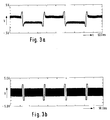
- the cell used in these measurements has a layer thickness of 1.5 ⁇ m.
- FIG. 1 b shows the composite voltage signal present at the pixels, while FIG. 1 a shows the transmission of the ferroelectric liquid crystal cell measured with a photodiode.
- ferroelectric liquid crystal displays have been characterized as bistable displays, while the control method according to the invention makes them multi-stable and thus capable of displaying gray levels.
- 2 shows a further control scheme according to the invention for a ferroelectric liquid crystal display which contains the liquid crystal specified above.
- the control scheme according to the invention is based on a conventional Bari 4: 3: 1 scheme (P. Maltese et al., 1988 Intern. Display Research Conference, "Fast Adressing Modes for Ferroelectric LC Display. Panels"), overlaid by much shorter pulses are.
- select pulse V s 36 V
- data pulse V d 7 V
- the write pulses are usually identified by the product vxt.
- the superimposed intermediate write pulse for changing the alignment state to an adjacent intermediate state should be a maximum of about 1/5 of the main write pulse which is required for switching between the two fully switched states with maximum and minimum transmission.
- the transmission difference between adjacent intermediate states can be varied within certain limits by varying the voltage pulse value of the superimposed intermediate pulses.
- the voltage pulse value Vt of the intermediate pulses must not be made too large, since on the one hand no intermediate states can then be generated and on the other hand there is still no switching between the two fully switched states. In the examples shown in FIGS.
- the ratio of the Vt values of the superimposed intermediate pulse to the main pulse is in each case approximately 1/10.
- the ratio of the Vt value of the intermediate pulses to the Vt value of the main pulses is preferably less than 0.15 and in particular not greater than 0.10.
- the width of the superimposed intermediate pulse is preferably not too large and in particular less than 3 microseconds. Between pulses with a pulse width of no more than 2 ⁇ s and in particular less than 1.5 ⁇ s are particularly preferred.
- the ratio of the Vt values of the intermediate pulses and the stabilizing AC pulses should, however, not be chosen to be less than about 2.0 and in particular greater than 2.5 and very particularly greater than 3.
- control method according to the invention allows a simple and very effective setting of gray values, the disadvantages occurring with conventional control schemes capable of generating gray values not being observed or being observed only to a much lesser extent.
- the method according to the invention is therefore of considerable economic importance.
Landscapes
- Physics & Mathematics (AREA)
- Chemical & Material Sciences (AREA)
- Crystallography & Structural Chemistry (AREA)
- Engineering & Computer Science (AREA)
- General Physics & Mathematics (AREA)
- Nonlinear Science (AREA)
- Computer Hardware Design (AREA)
- Theoretical Computer Science (AREA)
- Optics & Photonics (AREA)
- Liquid Crystal Display Device Control (AREA)
Applications Claiming Priority (2)
| Application Number | Priority Date | Filing Date | Title |
|---|---|---|---|
| DE4123696 | 1991-07-17 | ||
| DE19914123696 DE4123696A1 (de) | 1991-07-17 | 1991-07-17 | Ansteuerungsverfahren |
Publications (1)
| Publication Number | Publication Date |
|---|---|
| EP0523558A1 true EP0523558A1 (fr) | 1993-01-20 |
Family
ID=6436377
Family Applications (1)
| Application Number | Title | Priority Date | Filing Date |
|---|---|---|---|
| EP92111744A Withdrawn EP0523558A1 (fr) | 1991-07-17 | 1992-07-10 | Méthode de commande d'un afficheur à cristal liquide ferro-électrique |
Country Status (3)
| Country | Link |
|---|---|
| EP (1) | EP0523558A1 (fr) |
| JP (1) | JPH05281518A (fr) |
| DE (1) | DE4123696A1 (fr) |
Cited By (1)
| Publication number | Priority date | Publication date | Assignee | Title |
|---|---|---|---|---|
| WO1999059128A1 (fr) * | 1998-05-12 | 1999-11-18 | Kent State University | Systeme d'excitation biphasee cumulative d'afficheurs reflectifs cholesteriques bistables |
Families Citing this family (1)
| Publication number | Priority date | Publication date | Assignee | Title |
|---|---|---|---|---|
| GB9406742D0 (en) * | 1994-04-06 | 1994-05-25 | Crossland William A | Thin panel display screen |
Citations (1)
| Publication number | Priority date | Publication date | Assignee | Title |
|---|---|---|---|---|
| EP0373786A2 (fr) * | 1988-12-14 | 1990-06-20 | THORN EMI plc | Dispositif d'affichage |
Family Cites Families (2)
| Publication number | Priority date | Publication date | Assignee | Title |
|---|---|---|---|---|
| DE3815399A1 (de) * | 1987-05-08 | 1988-11-17 | Seikosha Kk | Verfahren zur ansteuerung einer optischen fluessigkristalleinrichtung |
| JPH07104506B2 (ja) * | 1989-03-14 | 1995-11-13 | スタンレー電気株式会社 | 強誘電性液晶パネル |
-
1991
- 1991-07-17 DE DE19914123696 patent/DE4123696A1/de not_active Withdrawn
-
1992
- 1992-07-10 EP EP92111744A patent/EP0523558A1/fr not_active Withdrawn
- 1992-07-17 JP JP19105492A patent/JPH05281518A/ja active Pending
Patent Citations (1)
| Publication number | Priority date | Publication date | Assignee | Title |
|---|---|---|---|---|
| EP0373786A2 (fr) * | 1988-12-14 | 1990-06-20 | THORN EMI plc | Dispositif d'affichage |
Non-Patent Citations (2)
| Title |
|---|
| JAPANESE JOURNAL OF APPLIED PHYSICS. Bd. 27, Nr. 8, Juli 1988, TOKYO JP Seiten 1115 - 1121 T. UMEDA ET AL. 'Influences of Alignment Materials and LC Layer Thickness on AC Field-Stabilization Phenomena of Ferroelectric Liquid Crystals' * |
| SID 1985 DIGEST OF TECHNICAL PAPERS, US Seiten 128 - 130 J.M GEARY 'A Multiplexed Ferroelectric LCD Using AC Field-Stabilized States' * |
Cited By (2)
| Publication number | Priority date | Publication date | Assignee | Title |
|---|---|---|---|---|
| WO1999059128A1 (fr) * | 1998-05-12 | 1999-11-18 | Kent State University | Systeme d'excitation biphasee cumulative d'afficheurs reflectifs cholesteriques bistables |
| US6204835B1 (en) | 1998-05-12 | 2001-03-20 | Kent State University | Cumulative two phase drive scheme for bistable cholesteric reflective displays |
Also Published As
| Publication number | Publication date |
|---|---|
| DE4123696A1 (de) | 1993-01-21 |
| JPH05281518A (ja) | 1993-10-29 |
Similar Documents
| Publication | Publication Date | Title |
|---|---|---|
| DE3717793C2 (fr) | ||
| DE68929032T2 (de) | Elektrooptische Einrichtung mit einem ferroelektrischen Flüssigkristall und Methode zu deren Herstellung | |
| DE3650013T2 (de) | Elektronische lenkung ferroelektrischer und flexoelektrischer flüssigkristallanordnungen. | |
| DE69012353T2 (de) | Flüssigkristall-Anzeigevorrichtung und Verfahren zu ihrer Ansteuerung. | |
| DE3448304C2 (fr) | ||
| DE69127393T2 (de) | Flüssigkristallanzeigevorrichtung | |
| DE3610801C2 (fr) | ||
| DE3686219T2 (de) | Verfahren zur ansteuerung eines fluessigkristallrasterbildschirmes. | |
| DE3630012A1 (de) | Ferroelektrische fluessigkristallvorrichtung | |
| DE3644220A1 (de) | Ansteuerungsverfahren fuer lichtmodulationsvorrichtungen | |
| DE3788724T2 (de) | Vorrichtungen mit einem smektischen flüssigkristall. | |
| DE69321279T2 (de) | Anzeigegerät | |
| DE69225685T2 (de) | Flüssigkristallzusammensetzung, Flüssigkristallvorrichtung und Anzeigevorrichtung | |
| CH662191A5 (de) | Verfahren und einrichtung zum anzeigen einer information. | |
| DE69320076T2 (de) | Verfahren zur Ansteuerung einer Flüssigkristall- Anzeigevorrichtung | |
| DE69228956T2 (de) | Ferroelektrisches Flüssigkristallelement | |
| DE69217154T2 (de) | Flüssigkristall-Anzeigevorrichtung | |
| DE69318276T2 (de) | Flüssigkristall-Vorrichtung und Flüssigkristall-Anzeigevorrichtung | |
| DE3650066T2 (de) | Ferroelektrische Flüssigkristallvorrichtungen. | |
| DE69524013T2 (de) | Ansteuerung für eine Ferroelectrische Flüsigkristallvorichtung | |
| DE69313801T2 (de) | Matrixanzeigevorrichtung | |
| EP0474655B1 (fr) | Affichage ferro-electrique a cristaux liquides presentant des paliers de gris et/ou une gamme continue des gris | |
| KR20010039965A (ko) | 액정소자 | |
| EP1198537B1 (fr) | Affichages a matrice active a contraste eleve | |
| DE602004005874T2 (de) | Bistabile ferroelektrische flüssigkristallzellen sowie -vorrichtungen mit siloxanoligomeren und deren verwendung |
Legal Events
| Date | Code | Title | Description |
|---|---|---|---|
| PUAI | Public reference made under article 153(3) epc to a published international application that has entered the european phase |
Free format text: ORIGINAL CODE: 0009012 |
|
| AK | Designated contracting states |
Kind code of ref document: A1 Designated state(s): DE GB |
|
| 17P | Request for examination filed |
Effective date: 19930624 |
|
| 17Q | First examination report despatched |
Effective date: 19950317 |
|
| STAA | Information on the status of an ep patent application or granted ep patent |
Free format text: STATUS: THE APPLICATION IS DEEMED TO BE WITHDRAWN |
|
| 18D | Application deemed to be withdrawn |
Effective date: 19950928 |