EP0523577A2 - Connexion entre un boulon et un élément porteur et palier articulé - Google Patents
Connexion entre un boulon et un élément porteur et palier articulé Download PDFInfo
- Publication number
- EP0523577A2 EP0523577A2 EP92111844A EP92111844A EP0523577A2 EP 0523577 A2 EP0523577 A2 EP 0523577A2 EP 92111844 A EP92111844 A EP 92111844A EP 92111844 A EP92111844 A EP 92111844A EP 0523577 A2 EP0523577 A2 EP 0523577A2
- Authority
- EP
- European Patent Office
- Prior art keywords
- bolt
- connection
- screw
- axle
- vehicle
- Prior art date
- Legal status (The legal status is an assumption and is not a legal conclusion. Google has not performed a legal analysis and makes no representation as to the accuracy of the status listed.)
- Withdrawn
Links
Images

Classifications
-
- B—PERFORMING OPERATIONS; TRANSPORTING
- B60—VEHICLES IN GENERAL
- B60G—VEHICLE SUSPENSION ARRANGEMENTS
- B60G9/00—Resilient suspensions of a rigid axle or axle housing for two or more wheels
- B60G9/02—Resilient suspensions of a rigid axle or axle housing for two or more wheels the axle or housing being pivotally mounted on the vehicle, e.g. the pivotal axis being parallel to the longitudinal axis of the vehicle
-
- B—PERFORMING OPERATIONS; TRANSPORTING
- B60—VEHICLES IN GENERAL
- B60G—VEHICLE SUSPENSION ARRANGEMENTS
- B60G7/00—Pivoted suspension arms; Accessories thereof
- B60G7/02—Attaching arms to sprung part of vehicle
-
- F—MECHANICAL ENGINEERING; LIGHTING; HEATING; WEAPONS; BLASTING
- F16—ENGINEERING ELEMENTS AND UNITS; GENERAL MEASURES FOR PRODUCING AND MAINTAINING EFFECTIVE FUNCTIONING OF MACHINES OR INSTALLATIONS; THERMAL INSULATION IN GENERAL
- F16C—SHAFTS; FLEXIBLE SHAFTS; ELEMENTS OR CRANKSHAFT MECHANISMS; ROTARY BODIES OTHER THAN GEARING ELEMENTS; BEARINGS
- F16C11/00—Pivots; Pivotal connections
- F16C11/02—Trunnions; Crank-pins
-
- B—PERFORMING OPERATIONS; TRANSPORTING
- B60—VEHICLES IN GENERAL
- B60G—VEHICLE SUSPENSION ARRANGEMENTS
- B60G2204/00—Indexing codes related to suspensions per se or to auxiliary parts
- B60G2204/40—Auxiliary suspension parts; Adjustment of suspensions
- B60G2204/44—Centering or positioning means
- B60G2204/4402—Spacers or shims
-
- F—MECHANICAL ENGINEERING; LIGHTING; HEATING; WEAPONS; BLASTING
- F16—ENGINEERING ELEMENTS AND UNITS; GENERAL MEASURES FOR PRODUCING AND MAINTAINING EFFECTIVE FUNCTIONING OF MACHINES OR INSTALLATIONS; THERMAL INSULATION IN GENERAL
- F16C—SHAFTS; FLEXIBLE SHAFTS; ELEMENTS OR CRANKSHAFT MECHANISMS; ROTARY BODIES OTHER THAN GEARING ELEMENTS; BEARINGS
- F16C2326/00—Articles relating to transporting
- F16C2326/01—Parts of vehicles in general
- F16C2326/05—Vehicle suspensions, e.g. bearings, pivots or connecting rods used therein
Definitions
- the invention relates to the connection between a bolt and a support part, at least part of the bolt projecting beyond the surface of the support part and being suitable for receiving at least one component by means of which forces acting transversely to the bolt axis can be introduced. Furthermore, the invention relates to the pendulum mounting for a vehicle axle, in particular for the front axle of an agricultural or commercial vehicle, with at least one pivotable pin connection arranged between an axle carrier of the vehicle and the vehicle axle, in which a pin is rigidly connected to the axle carrier or to the vehicle axle and in engages a recess of the vehicle axle or the axle support.
- connection of this type are used, for example, in the pendulum mounting of the front axle of a tractor, in which a pendulum pin is pressed into the front axle support.
- the axle body with its hole can be pushed over the pendulum pin.
- a high force-absorbing press fit is required, in which the minimum pressing depth of approximately the simple one of the bolt diameter must be observed. Therefore, the front axle support must have an appropriate material thickness and material quality.
- the object to be achieved with the invention is seen in providing a non-positive connection of the type mentioned at the outset, which is detachable and suitable for relatively thin supporting parts to which low material quality requirements are imposed.
- the bolt contains a collar
- the surface facing the support part is pressed by means of a screw connection against a surface of the support part, the screw connection having a central bolt which cooperates with the support part.
- the screw is only subjected to tensile stress, but not to shear forces.
- connection according to the invention is releasable. With it, the moments that occur as a result of the forces acting transversely to the pin axis are not taken up within an interference fit. Rather, the bolt is supported by the collar formed on it on the surface of the supporting part. This is made possible by pressing the bolt onto the supporting part by means of a high-strength screw, if necessary. The transverse forces are absorbed by friction between the collar and the surface of the support part. The thickness of the supporting part is not decisive for the forces that can be transmitted from the bolt to the supporting part.
- a homogeneous compressive stress field is formed on the contact surface between the collar and the supporting part due to the tensile stress of the screw connection.
- This compressive stress field is superimposed on the tensile-compressive stress field typical of the bending stress (superposition principle).
- the homogeneous compressive stress field should be sufficiently large so that the compressive stress due to the screw connection is greater than the bending stress in every area of the contact surface at maximum bending stress. In extreme cases, however, the connection can also absorb a bending stress, which leads to a one-sided partial lifting of the collar from the support plate.
- the compressive preload generated by the bolt preload force in the bolt also increases the strength of the bolt.
- the bolt expediently contains a cylindrical pin for receiving the component.
- This pin can be inserted into a hole in the component introducing the transverse forces.
- the connection between the bolt and the component can be designed so that the component can be pivoted about the bolt axis. This training is suitable for the self-aligning bearing of a vehicle axle. In the case of an inexpensive design, the entire bolt with the collar and pin is designed as a turned part.
- a washer is arranged between the back of the supporting part and the screw head or a nut that can be screwed onto the screw.
- the surface of the disk resting on the support part is approximately the same size as the flange surface lying on the other side of the support part.
- the washer is used for the large-scale introduction of force into the supporting part and is particularly advantageous for relatively thin supporting parts and low material qualities.
- a further disk is preferably provided which can be fastened with the screw at the free end of the bolt and which extends radially beyond the bolt cross section.
- a stub is formed on the bolt on the side of the collar facing the support part and extends into a recess of the support part corresponding to the stub cross section. Through this stub transverse forces that go beyond the amount to be absorbed by friction can be transmitted to the support member.
- the stub also serves to position and center the bolt on the supporting part.
- Another object to be achieved with the invention is seen in specifying a self-aligning bearing for a vehicle axle with a pivotable bolt connection which only requires relatively small wall thicknesses of the component which receives the bolt and which allows simple, rapid assembly without spacing by means of washers while observing the required assembly dimensions.
- connection between the bolt and the receiving support part of the type according to the invention.
- Such a connection enables simple quick assembly and disassembly of the bolt and the pendulum bearing.
- the bolt is usually surface hardened due to the high load.
- the surface facing away from the supporting part of the collar formed on the bolt can thus serve as a contact surface for the bearing eye of the articulated component without a hardened thrust ring having to be interposed, as is customary in known self-aligning bearings.
- connection aligned with one another and oriented in the longitudinal direction of the vehicle, are provided, at least one connection containing a disk which can be fastened to the free end of the pin and projects beyond the cross section of the pin.
- the bolts are attached to the axle carrier and their pins are aligned with the rear of the vehicle. Tins can be stuck on the pins.
- the axle body contains bearing eyes that can be pushed over the bushings.
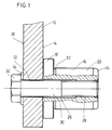
- FIG. 1 shows the partial area of a housing 10, flange or the like serving as a supporting part with a through bore 12, on one side 14 of which an end face of a rotationally symmetrical bolt 16 which is aligned with the through bore 12 bears.
- the bolt 16 consists essentially of a collar 18 and a pin 20. Between the collar 18 and pin 20 there is an undercut 22.
- the free end of the pin 20 is provided with a frustoconical phase 24, which the insertion of the pin 20 into the bore a component, not shown, which can be rotatably supported on the pin 20 of the pin 16, facilitated.
- the bolt 16 has an axial bore which is divided into a cylindrical section 26 and a threaded section 28.
- the threaded section 28 is located in the region of the free end of the pin 20.
- a screw 30 extends through the through bore 12 of the housing 10 and the bore of the bolt 16 and is screwed into the threaded section 28.
- the screw head 32 is supported by a washer 34 on the surface 36 of the housing 10 facing away from the bolt 16.
- the screw 30 is a high-strength screw that absorbs high tensile forces. Through them, the end face of the collar 18 facing away from the pin 20 is pressed against the side 14 of the housing 10. The area of this side 14 of the housing 10 which serves as the contact surface can be machined in order to ensure that the pin 16 fits precisely.
- a high tension of the screw 30 leads to a high contact pressure between the collar 18 and the housing 10.
- This contact pressure brings about a good frictional connection between the collar 18 and the housing 10, which absorbs high transverse forces which are transmitted from the component (not shown) to the bolt 16. allowed.
- the moments that occur are supported via the collar 18 as normal forces on the side 14 of the support plate 10. The larger the diameter of the collar 18, the greater the moments that can be transmitted.
- FIG. 2 shows a pendulum mounting for the steerable front axle of a tractor, which is shown in a section running longitudinally to the direction of travel.
- the front axle center piece 40 which is connected to the front wheels 42 of the agricultural tractor, not shown, is supported by two links 44 and 46 according to the invention on two brackets 48, 50, which are part of a front axle carrier, not shown, and thus the vehicle chassis.
- the connections 44, 46 each contain a concentrically formed bolt 52, 54, which are essentially composed of three sections, namely a pin 56, 58, a collar 60, 62 and a stub 64, 66, pins 56, 58 and stub 64, 66 each on opposite Pages of the Confederation 60, 62 lie.
- the stubs 64, 66 are each inserted into a through hole in the associated tab 48, 50.
- the end face of the collar 60, 62 facing the stub 64, 66 bears against the side face 68, 70 of the tab 48, 50.
- a continuous, axial, cylindrical bore (not shown) extends through the front bolt 52 and receives the shaft of a screw 72.
- the rear bolt 54 is designed in terms of its through hole similar to that described with reference to FIG. 1.
- a screw 74 is screwed into its threaded section. The screws 72, 74 serve to fasten the bolts 52, 54 to the tabs 48, 50.
- the screw head 76 is supported on a washer 78 which bears on the free end face of the pin 56 and whose outer diameter is larger than the diameter of the pin 56.
- the threaded end 80 of the screw 72 projects beyond that facing away from the bolt 52
- Side 81 of the tab 48 and carries a thrust washer 82 and a nut 84.
- the screw connection between the tab 50 and the bolt 54 is configured similarly to the embodiment according to FIG. 1.
- the washer 34 instead of the washer 34 there is a thrust washer 86 so that the tab 50 is clamped between the thrust washer 86 and the collar 62 of the bolt 54.
- the front axle center piece 40 carries a front upward bearing eye 88 and a rear upward bearing eye 90.
- the cylindrical through holes Both bearing eyes 88, 90, into which the bearing bushings 92 are fitted, are aligned with one another and are aligned in the direction of travel of the agricultural tractor.
- the pins 56, 58 of the associated bolt 52, 54 are rotatably mounted in the bearing bushes 92.
- the front bearing eye 88 is located between the collar 60 of the front bolt 52 and the washer 78. A slight axial play enables the bearing eye 88 to be rotated above the bolt 52.
- the spacing ratios of the tabs 48, 50 and bearing eyes 88, 90 are selected such that There is a sufficient distance between the rear bearing eye 90 and the collar 62 of the associated bolt 54, by means of which bearing bearing 90 against the collar 62 is avoided.
- the stubs 64, 66 are fitted with a sliding or press fit into the through holes of the tabs 48, 50, so that after loosening the screws 72, 74, the bolts 52, 54 are pulled out of the tabs 48, 50 or driven by means of a mandrel can be. They serve to center the bolts 52, 54. In addition, they are able to transmit transverse forces transmitted from the bearing eyes 88, 90 to the bolts 52, 54, which go beyond the amount to be absorbed by friction, to the straps 48, 50.
- the diameter of the thrust washers 82, 86 is larger than that of the stub 64, 66 and almost as large as the diameter of the collars 60, 62.
- the thrust washers 82, 86 serve to introduce the force of the tensile force exerted by the screws 72, 74 into the tabs 48, 50.
- the rear bolt 54 is first attached to the bracket 50 by inserting its stub 66 into the through hole of the bracket 50 inserted and then screw 74 is screwed into bolt 54. Then the front pin 52 is inserted with its stub 64 into the through hole of the front plate 48, but without screwing it. The front axle is brought into its installed position, and the bearing eyes 88, 90, into which the bearing bushes 92 are inserted, are pushed over the pins 56, 58. Now the screw 72 is inserted with the washer 78 and the thrust washer 82, and by tightening the nut 84, the bolt 52 is attached to the tab 48.
- the disassembly is carried out in the reverse order, however as a rule the rear bolt 54 does not need to be removed from the tab 50. No spacers such as washers are required for assembly. All that is required as an assembly tool is an ordinary wrench.
Landscapes
- Engineering & Computer Science (AREA)
- Mechanical Engineering (AREA)
- General Engineering & Computer Science (AREA)
- Pivots And Pivotal Connections (AREA)
Applications Claiming Priority (2)
| Application Number | Priority Date | Filing Date | Title |
|---|---|---|---|
| DE4123624A DE4123624C2 (de) | 1991-07-17 | 1991-07-17 | Verbindung zwischen Bolzen und Tragteil sowie Pendellagerung |
| DE4123624 | 1991-07-17 |
Publications (2)
| Publication Number | Publication Date |
|---|---|
| EP0523577A2 true EP0523577A2 (fr) | 1993-01-20 |
| EP0523577A3 EP0523577A3 (en) | 1994-06-15 |
Family
ID=6436321
Family Applications (1)
| Application Number | Title | Priority Date | Filing Date |
|---|---|---|---|
| EP19920111844 Withdrawn EP0523577A3 (en) | 1991-07-17 | 1992-07-11 | Connection between a bolt and a supporting member and oscillating bearing |
Country Status (2)
| Country | Link |
|---|---|
| EP (1) | EP0523577A3 (fr) |
| DE (1) | DE4123624C2 (fr) |
Cited By (2)
| Publication number | Priority date | Publication date | Assignee | Title |
|---|---|---|---|---|
| EP1426204A3 (fr) * | 2002-12-06 | 2005-01-12 | Fiat Kobelco Construction Machinery S.p.A. | Véhicule avec essieu oscillant |
| CN117022334A (zh) * | 2023-06-27 | 2023-11-10 | 北京起重运输机械设计研究院有限公司 | 索道吊具连接装置和缆车 |
Family Cites Families (3)
| Publication number | Priority date | Publication date | Assignee | Title |
|---|---|---|---|---|
| DE1872222U (de) * | 1963-03-19 | 1963-05-16 | Albert Nestler A G | Lagerbuechse fuer drehzapfen zum auskleiden einer bohrung. |
| DE3205716C2 (de) * | 1982-02-18 | 1985-03-28 | Daimler-Benz Ag, 7000 Stuttgart | Elastisch nachgiebiges Schwenklager zur gegenseitigen schwenkbaren Verbindung eines tragenden und eines schwenkbaren Teiles eines Kraftfahrzeuges, beispielsweise eines Radträgers mit einem Radführungsglied |
| DE3722243A1 (de) * | 1987-07-06 | 1989-01-19 | Skf Gmbh | Anordnung zur axialen abstuetzung |
-
1991
- 1991-07-17 DE DE4123624A patent/DE4123624C2/de not_active Expired - Fee Related
-
1992
- 1992-07-11 EP EP19920111844 patent/EP0523577A3/de not_active Withdrawn
Cited By (2)
| Publication number | Priority date | Publication date | Assignee | Title |
|---|---|---|---|---|
| EP1426204A3 (fr) * | 2002-12-06 | 2005-01-12 | Fiat Kobelco Construction Machinery S.p.A. | Véhicule avec essieu oscillant |
| CN117022334A (zh) * | 2023-06-27 | 2023-11-10 | 北京起重运输机械设计研究院有限公司 | 索道吊具连接装置和缆车 |
Also Published As
| Publication number | Publication date |
|---|---|
| DE4123624A1 (de) | 1993-01-21 |
| DE4123624C2 (de) | 1994-11-03 |
| EP0523577A3 (en) | 1994-06-15 |
Similar Documents
| Publication | Publication Date | Title |
|---|---|---|
| DE3831948C2 (fr) | ||
| DE102006011823A1 (de) | Positioniereinrichtung | |
| DD286977A5 (de) | Walzvorrichtung mit einem auf einer welle angeordneten walzring | |
| EP3924645A1 (fr) | Vis d'entraînement à roulement planétaire et actionneur pour une direction d'essieu arrière d'un véhicule à moteur équipé d'une telle vis d'entraînement à roulement planétaire | |
| DE3740401C2 (fr) | ||
| EP0475216A1 (fr) | Dispositif d'assemblage entre des poutres et des noeuds d'une structure tridimensionelle | |
| DE2003028B2 (de) | Teilbelagscheibenbremse | |
| DE10315534B4 (de) | Spannhülse mit Mutter | |
| DE102007009779C5 (de) | Drehverbindung zwischen Welle und Ritzel und Verfahren zu deren Herstellung | |
| DE102010024619B4 (de) | Vorgespanntes Differentialgetriebe ohne Zahnflankenwechsel | |
| DE102018200323A1 (de) | Blattfederanordnung für Kraftfahrzeuge | |
| DE2932248A1 (de) | Anordnung zum axialen fixieren und/oder anstellen von maschinenteilen | |
| EP0523577A2 (fr) | Connexion entre un boulon et un élément porteur et palier articulé | |
| DE19713678A1 (de) | Klemmbeschlag für die Befestigung von Glasscheiben | |
| EP4291794B1 (fr) | Accouplement souple à cardan permettant de transmettre des forces axiales élevées pour des transmissions dans des éoliennes | |
| WO1990008272A1 (fr) | Raccord a bride resistant a la torsion | |
| DE19939729C2 (de) | Antriebsanordnung | |
| DE19735753A1 (de) | Drehstabanordnung | |
| EP1019642A1 (fr) | Articulation pour joints articules appropries a la transmission de couple | |
| DE2158779B2 (de) | Nachstellbare Maschinenreibahle | |
| DE2932879C2 (de) | Vorrichtung zur kraftschlüssigen, drehmomentübertragenden Verbindung einer Welle mit einem Nabenteil | |
| DE102017214320B4 (de) | Aktuator einer Hinterachslenkung für ein Kraftfahrzeug | |
| EP3825202B1 (fr) | Barre de traction, en particulier pour un accouplement de pare-chocs central d'un véhicule ferroviaire, et écrou destinée au raccordement d'un tirant ancrage d'une barre de traction à un tube de traction de la barre de traction | |
| DE202006020729U1 (de) | Einstellvorrichtung für die Montage von Zahnstangen | |
| EP4590985A1 (fr) | Porte-satellites |
Legal Events
| Date | Code | Title | Description |
|---|---|---|---|
| PUAI | Public reference made under article 153(3) epc to a published international application that has entered the european phase |
Free format text: ORIGINAL CODE: 0009012 |
|
| AK | Designated contracting states |
Kind code of ref document: A2 Designated state(s): AT BE CH DE ES FR GB IT LI |
|
| PUAL | Search report despatched |
Free format text: ORIGINAL CODE: 0009013 |
|
| AK | Designated contracting states |
Kind code of ref document: A3 Designated state(s): AT BE CH DE ES FR GB IT LI |
|
| STAA | Information on the status of an ep patent application or granted ep patent |
Free format text: STATUS: THE APPLICATION IS DEEMED TO BE WITHDRAWN |
|
| 18D | Application deemed to be withdrawn |
Effective date: 19941216 |