EP0523663B2 - Accouplement hydraulique à accélération rapide - Google Patents
Accouplement hydraulique à accélération rapide Download PDFInfo
- Publication number
- EP0523663B2 EP0523663B2 EP92112085A EP92112085A EP0523663B2 EP 0523663 B2 EP0523663 B2 EP 0523663B2 EP 92112085 A EP92112085 A EP 92112085A EP 92112085 A EP92112085 A EP 92112085A EP 0523663 B2 EP0523663 B2 EP 0523663B2
- Authority
- EP
- European Patent Office
- Prior art keywords
- rotational speed
- fluid coupling
- oil
- lowest
- working chamber
- Prior art date
- Legal status (The legal status is an assumption and is not a legal conclusion. Google has not performed a legal analysis and makes no representation as to the accuracy of the status listed.)
- Expired - Lifetime
Links
- 230000008878 coupling Effects 0.000 title claims description 45
- 238000010168 coupling process Methods 0.000 title claims description 45
- 238000005859 coupling reaction Methods 0.000 title claims description 45
- 239000012530 fluid Substances 0.000 title claims description 41
- 230000001133 acceleration Effects 0.000 title claims description 27
- 239000003921 oil Substances 0.000 claims description 41
- 239000010720 hydraulic oil Substances 0.000 claims description 29
- 230000008859 change Effects 0.000 claims description 6
- 238000007599 discharging Methods 0.000 claims 1
- 230000004044 response Effects 0.000 description 17
- XEEYBQQBJWHFJM-UHFFFAOYSA-N Iron Chemical compound [Fe] XEEYBQQBJWHFJM-UHFFFAOYSA-N 0.000 description 2
- 229910000831 Steel Inorganic materials 0.000 description 1
- 230000009471 action Effects 0.000 description 1
- 230000003247 decreasing effect Effects 0.000 description 1
- 230000000694 effects Effects 0.000 description 1
- 229910052742 iron Inorganic materials 0.000 description 1
- 239000000463 material Substances 0.000 description 1
- 230000007246 mechanism Effects 0.000 description 1
- 230000002093 peripheral effect Effects 0.000 description 1
- 239000010959 steel Substances 0.000 description 1
Images


Classifications
-
- F—MECHANICAL ENGINEERING; LIGHTING; HEATING; WEAPONS; BLASTING
- F16—ENGINEERING ELEMENTS AND UNITS; GENERAL MEASURES FOR PRODUCING AND MAINTAINING EFFECTIVE FUNCTIONING OF MACHINES OR INSTALLATIONS; THERMAL INSULATION IN GENERAL
- F16D—COUPLINGS FOR TRANSMITTING ROTATION; CLUTCHES; BRAKES
- F16D33/00—Rotary fluid couplings or clutches of the hydrokinetic type
- F16D33/06—Rotary fluid couplings or clutches of the hydrokinetic type controlled by changing the amount of liquid in the working circuit
- F16D33/16—Rotary fluid couplings or clutches of the hydrokinetic type controlled by changing the amount of liquid in the working circuit by means arranged externally of the coupling or clutch
Definitions
- This type of fluid coupling functions for the purpose of controlling the number of revolutions (i.e., rotational speed) of the driven side and of no-load starting of an electric motor on the driving side and enables a lowering in the running cost and also a lowering in the driving machine cost.
- This type of fluid coupling functions to cut off power (clutch action), absorb torsional vibration, effect no load starting of a prime mover and reduce starting resistance, and enables individual operation of an engine, on-off operation of a driven machine, easy starting and acceleration of a prime mover, etc.
- Fig. 10(c) shows schematically the above-described fixed speed (fixed charge type) fluid coupling, which is designed to operate with the circuit filled with a fluid at all times.
- This type of fluid coupling functions for the purpose of reducing the starting resistance, lessening and absorbing vibration and impact and absorbing torsional vibration and also functions as a torque limiter, and it functions to protect an electric motor and machine connected thereto.
- the conventional variable speed type fluid coupling (shown in Fig. 10(a)) enables a desired rotational speed to be set over a wide controllable range by varying the position of the scoop tube 109 and is therefore suitable for a multi-point operation.
- the acceleration response speed that is, the time needed to increase the rotational speed from its lowest to highest, of this type of fluid coupling is relatively slow, e.g. about 10 seconds at its fastest.
- the oil charge-discharge type fluid coupling (shown in Fig. 10(b)) allows the rotational speed to be changed over between two points, i.e., the highest rotational speed and the lowest rotational speed, by opening and closing the oil charge-discharge switching valve 111 and is therefore suitable for sole operation of a driving machine and an on-off operation of a driven machine.
- the hydraulic oil is discharged from the nozzle 114, provided at the outer periphery of the hydraulic oil chamber, at all times during the operation of the driven machine, it leads to a lowering in the efficiency in the case of a small-sized fluid coupling.
- the acceleration-deceleration response speed is slow. Therefore, this type of fluid coupling cannot be applied to uses where a fast acceleration-deceleration response speed is required.
- the fixed speed fluid coupling (shown in Fig. 10(c)) is suitable mainly for absorbing and reducing impact force but is unable to control the rotational speed.
- An object of the present invention is, therefore, to solve the above-described problems of the prior art and markedly improve on the response time in rotational speed in a change from its lowest to highest speed and vice versa by using a quick acceleration mechanism of a fluid coupling.
- the fluid coupling includes the characterizing portion of claim 1.
- a dam is provided on an inner surface of the impeller casing inwardly of an oil discharge nozzle provided in the impeller casing so that a lowest rotational speed can be set as desired. It is also possible for a plurality of small notches to be provided in the innermost periphery of the lowest speed setting dam so that the lowest rotational speed can be subject to minute variations.
- the height of said dam may set so that a driving machine of said coupling will not exceed its load carrying capacity limit due to acceleration torque generated when the rotational speed is changed from its lowest to its highest speed.
- the control valve may be arranged to make it possible to set a rate of supply of oil into said working chamber so that a driving machine will not exceed its load carrying capacity limit due to acceleration torque generated when the rotational speed is changed rapidly from its lowest to its highest speed.
- the driving side which comprises the driving shaft, the impeller and the impeller casing
- the driving side which comprises the driving shaft, the impeller and the impeller casing
- the driving machine will not exceed its load carrying capacity limit as a result of the acceleration torque.
- the open-close speed of the control valve or the size of the oil control orifice may be changed according to the circumstances to set a rate of supply of hydraulic oil into the working chamber so that the driving machine will not exceed its load carrying capacity limit due to the acceleration torque.
- Fig. 1 shows a hydraulic oil supply circuit of a fluid coupling according to one embodiment of the present invention
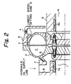
- Fig. 2 is a vertical sectional view showing the structure of the fluid coupling.
- an impeller 2 is attached to a driving shaft 1, and a runner 3 is attached to a driven shaft 4 in opposing relation to the impeller 2 to constitute a fluid circuit.
- An impeller casing 5 that surrounds the outer periphery of the runner 3 is attached to the impeller 2 and has a nozzle k provided in the outer peripheral wall portion thereof to discharge hydraulic oil to the outside.
- a dam D for setting the lowest speed is formed on the inner wall surface of the casing 5 at the inner side of the position where the nozzle K is provided.
- the impeller 2 has a hydraulic oil supply hole 6 provided in the radially inward portion thereof, the oil supply hole 6 being communicated with a passage 8 that is formed in a driving-side bearing casing 7 to connect with a hydraulic oil supply line.
- reference numeral 9 denotes a driven-side bearing casing, and 7a and 9a bearing sliding members.
- the lowest rotational speed N 1 is increased by increasing the dimension y of the dam D shown in Fig. 3 to thereby reduce (N 2 -N 1 ), and thus lowering the acceleration torque Ta.
- the acceleration time t may be increased to thereby lower the acceleration torque Ta.
- the acceleration time t may be increased by changing the bore diameters of the oil control orifices j and h shown in Fig. 1, or by changing the open-close speed of the control valve f.
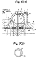
- Fig. 5(a) is a vertical sectional view of a fluid coupling having a lowest speed setting dam Da which is arranged to enable the lowest speed to be changed minutely
- Fig. 5(b) is a side view of the dam Da (the whole circumference).
- the dam Da has an even number of small semicircular notches 10 provided in the innermost periphery thereof at respective positions of central symmetry.
- the dam Da has an even number of small semicircular notches 10 provided in the innermost periphery thereof at centrally symmetrical positions as described above.
- the flow rate of oil passing through the notches 10 is varied, and it is possible to minutely control the oil film thickness of the overflowing oil and hence possible to change the lowest speed minutely.
- the lowest speed can be set as designed.
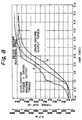
- Figs. 7 and 8 are graphs showing the results of calculation wherein response characteristics of the driven machine rotational speed, the driven machine output torque and the sum of the driven machine output torque and the acceleration torque (ordinate axis) were obtained for different periods of time to supply hydraulic oil into the impeller working chamber, i.e., 3 seconds and 5 seconds (abscissa axis).
- the acceleration torque increases in inverse proportion to the acceleration time.
- the sum of the acceleration torque and the driven machine output torque shown in each graph is the load applied to the driving machine, and the acceleration time (hydraulic oil supply time) t and the lowest rotational speed N 1 must be set so that the load will not exceed the load carrying capacity limit of the driving machine.
- the dimension y of the dam D is determined so that the lowest rotational speed is 1,775 r.p.m., and the highest rotational speed is set at 6,597 r.p.m.
- the acceleration torque is almost halved, and the acceleration response time is about 3.1 seconds and 5.1 seconds.
- the response speed is improved by a large margin in comparison with the conventional scoop tube system (shown in Fig. 10(a)).
- Fig. 9 shows the response characteristics of the prior art, i.e., scoop tube system.
- the lowest and highest rotational speeds are set at 1,775 r.p.m. and 6,597 r.p.m., respectively, in the same way as in the examples shown in Figs. 7 and 8, since the scoop tube moving time is 10 seconds, the acceleration response time also needs about 10 seconds. If the dead time and the response lag of first order are taken into consideration in the above examples, the actual acceleration response time may be about 1 second longer than the above-described acceleration response time in each example.
- a passage for supplying hydraulic oil into a fluid coupling working chamber defined by an impeller, a runner and an impeller casing is provided with a control valve that is operable to be fully opened and closed rapidly and further provided with a bypass passage having an oil control orifice, which bypasses the control valve, the response time in rotational speed change from the lowest to the highest and vice versa can be greatly shortened.
- the lowest rotational speed can be changed minutely by providing small notches in the innermost periphery of the lowest speed setting dam.
- overload of a driving machine can be prevented by setting the height of the lowest speed setting dam or the open-close speed of the control valve or the size of the oil control orifice so that the driving machine will not exceed its load carrying capacity limit due to the acceleration torque generated when the rotational speed is increased rapidly from its lowest to highest speed.
Landscapes
- Engineering & Computer Science (AREA)
- General Engineering & Computer Science (AREA)
- Mechanical Engineering (AREA)
- Supercharger (AREA)
- Control Of Positive-Displacement Air Blowers (AREA)
Claims (5)
- Accouplement fluidique comprenant une chambre de travail (C) de l'accouplement fluidique comportantcaractérisé en ce queun rotor (2) fixé à un arbre d'entraínement (1),une coque tournante (3) fixée à un arbre mené (4),un carter (5) de rotor, fixé audit rotor (2) et entourant ladite coque tournante (3), ledit carter (5) du rotor comprenant une buse de refoulement (k) servant à refouler librement de l'huile hydraulique à partir de ladite chambre de travail (C) de l'accouplement fluidique, à l'extérieur de cette chambre, etun passage (l1) pour envoyer de l'huile hydraulique dans ladite chambre de travail (C) de l'accouplement fluidique, et des moyens de commande disposés dans ledit passage (l1) et comprenant une soupape (f) pouvant agir d'une manière pouvant être sélectionnée pour être ouverte et fermée complètement pour modifier la vitesse de rotation dudit arbre mené entre des vitesses de rotation maximale et minimale,
lesdits moyens de commande comprennent en outre :la commande étant agencée de manière à modifier sélectivement et rapidement la vitesse de rotation dudit arbre mené (4) depuis une vitesse de rotation minimale de l'arbre mené rotatif, à laquelle la soupape de commande (f) est totalement fermée et la quantité d'huile envoyée à la chambre de travail (C) est déterminée par ledit orifice (h) de commande de l'huile, à une vitesse de rotation maximale, à laquelle la quantité de l'huile envoyée à la chambre de travail (C) est déterminée par la soupape de commande (f) totalement ouverte et par ledit orifice (h) de commande de l'huile ou vice-versa suivant le fonctionnement de ladite soupape de commande (f), et en ce qu'un organe de retenue (D) est prévu sur une surface intérieure dudit carter (5) du rotor, sur le côté intérieur par rapport à ladite buse (k) de refoulement de l'huile, pour le réglage de la vitesse de rotation minimale dudit arbre mené (4).un passage de dérivation (l2) qui comporte un orifice (h) de commande de l'huile qui contourne ladite soupape de commande (f), - Accouplement fluidique selon la revendication 1, dans lequel une pluralité de petites encoches (10) sont prévues dans la périphérie la plus intérieure dudit organe de retenue (D).
- Accouplement fluidique selon la revendication 2, dans lequel lesdites encoches (10) ont chacune une forme semi-circulaire et sont disposées symétriquement par rapport au centre dudit organe de retenue (D).
- Accouplement fluidique selon la revendication 1, dans lequel la hauteur (y) dudit organe de retenue (D) est réglée de telle sorte qu'une machine d'entraínement dudit accouplement ne dépasse pas sa capacité limite de support de charge compte tenu du couple d'accélération produit lorsque la vitesse de rotation dudit arbre mené (4) est commutée de sa valeur minimale à sa valeur maximale.
- Accouplement fluidique selon la revendication 1, dans lequel un débit d'alimentation maximum en huile pénétrant dans ladite chambre de travail (C) desdits moyens (f) formant soupape de commutation est réglé de telle sorte qu'une machine d'entraínement ne dépasse pas sa capacité limite de support de charge compte tenu du couple d'accélération produit lorsque la vitesse de rotation dudit arbre mené (4) est commutée rapidement de sa valeur minimale à sa valeur maximale conformément à l'actionnement desdits moyens (f) formant soupape de commutation.
Applications Claiming Priority (3)
| Application Number | Priority Date | Filing Date | Title |
|---|---|---|---|
| JP3175510A JPH0830506B2 (ja) | 1991-07-16 | 1991-07-16 | 急加速流体継手 |
| JP17551091 | 1991-07-16 | ||
| JP175510/91 | 1991-07-16 |
Publications (5)
| Publication Number | Publication Date |
|---|---|
| EP0523663A2 EP0523663A2 (fr) | 1993-01-20 |
| EP0523663A3 EP0523663A3 (fr) | 1994-01-05 |
| EP0523663B1 EP0523663B1 (fr) | 2000-01-26 |
| EP0523663B2 true EP0523663B2 (fr) | 2004-09-15 |
| EP0523663B9 EP0523663B9 (fr) | 2005-01-26 |
Family
ID=15997315
Family Applications (1)
| Application Number | Title | Priority Date | Filing Date |
|---|---|---|---|
| EP92112085A Expired - Lifetime EP0523663B9 (fr) | 1991-07-16 | 1992-07-15 | Accouplement hydraulique à accélération rapide |
Country Status (4)
| Country | Link |
|---|---|
| US (1) | US5406792A (fr) |
| EP (1) | EP0523663B9 (fr) |
| JP (1) | JPH0830506B2 (fr) |
| DE (1) | DE69230604T3 (fr) |
Families Citing this family (7)
| Publication number | Priority date | Publication date | Assignee | Title |
|---|---|---|---|---|
| US6104948A (en) * | 1996-04-03 | 2000-08-15 | The United States Of America As Represented By The Administrator Of The National Aeronautics And Space Administration | Method for visually integrating multiple data acquisition technologies for real time and retrospective analysis |
| EP1364139B1 (fr) | 2000-12-04 | 2005-03-02 | Ebara Corporation | Coupleur hydraulique |
| DE10327133B4 (de) * | 2003-06-13 | 2006-01-12 | Voith Turbo Gmbh & Co. Kg | Hydrodynamische Kupplung und Antriebseinheit mit einer hydrodynamischen Kupplung |
| DE102004015706B4 (de) * | 2004-03-29 | 2012-12-06 | Voith Turbo Gmbh & Co. Kg | Hydrodynamische Baueinheit und Verfahren zur Beschleunigung des Befüllvorganges einer hydrodynamischen Baueinheit |
| US7818965B2 (en) * | 2006-07-20 | 2010-10-26 | Chrysler Group Llc | Torque converter output augmentation method and apparatus |
| CN101825166A (zh) * | 2010-04-30 | 2010-09-08 | 中国北车集团大连机车研究所有限公司 | 调速型液力偶合器垂直反车传动装置 |
| KR101685376B1 (ko) * | 2016-06-28 | 2016-12-21 | (주) 상용이엔지 | 구동속도 조절이 가능한 유체커플링 |
Citations (2)
| Publication number | Priority date | Publication date | Assignee | Title |
|---|---|---|---|---|
| DE3441510A1 (de) † | 1984-11-14 | 1986-05-15 | Voith-Turbo Gmbh & Co Kg, 7180 Crailsheim | Fluessigkeitskreislauf fuer eine hydrodynamische kupplung |
| JPH03140633A (ja) † | 1989-10-25 | 1991-06-14 | Hitachi Ltd | 流体継手の運転方法 |
Family Cites Families (17)
| Publication number | Priority date | Publication date | Assignee | Title |
|---|---|---|---|---|
| US2432191A (en) * | 1944-01-19 | 1947-12-09 | Wright Aeronautical Corp | Fluid coupling automatic control valve |
| US2689458A (en) * | 1950-05-25 | 1954-09-21 | Weymann Charles Terres | Rotary hydraulic coupling |
| US2878642A (en) * | 1955-10-22 | 1959-03-24 | Ferodo Sa | Hydraulic coupling and means for controlling the quantity of fluid therein |
| US3146595A (en) * | 1959-10-28 | 1964-09-01 | Armco Steel Corp | Control system for fluid coupling |
| US3324650A (en) * | 1964-09-26 | 1967-06-13 | Voith Getriebe Kg | Apparatus for controlling an installation with drive motor and a hydrodynamic transmission, especially for rail vehicles with diesel engine |
| JPS521460B2 (fr) * | 1971-10-18 | 1977-01-14 | ||
| JPS4933312A (fr) * | 1972-07-31 | 1974-03-27 | ||
| JPS5061569A (fr) * | 1973-10-03 | 1975-05-27 | ||
| JPS521460A (en) * | 1975-06-24 | 1977-01-07 | Casio Computer Co Ltd | Interconnector |
| GB1497960A (en) * | 1975-06-27 | 1978-01-12 | Voith Turbo Kg | Hydrodynamic couplings |
| JPS53140467A (en) * | 1977-05-14 | 1978-12-07 | Kawasaki Heavy Ind Ltd | Variable speed fluid joint provided with clutch function |
| JPS5569351A (en) * | 1978-11-17 | 1980-05-24 | Nissan Motor Co Ltd | Transmission hydraulic control device for industrial vehicle |
| JPS57129932A (en) * | 1981-02-04 | 1982-08-12 | Hitachi Ltd | Method of rapidly starting variable-speed fluid coupling |
| DE3240179A1 (de) * | 1981-10-30 | 1983-06-16 | Ebara Corp., Tokyo | Stroemungsmittelkupplung |
| DE3531987A1 (de) * | 1985-09-07 | 1987-04-16 | Bergwerksverband Gmbh | Stroemungskupplung mit schnellentleerung und -befuellung |
| JPH0245536Y2 (fr) * | 1986-12-17 | 1990-12-03 | ||
| JP2951994B2 (ja) * | 1990-03-08 | 1999-09-20 | 株式会社荏原製作所 | 流体継手の変速装置 |
-
1991
- 1991-07-16 JP JP3175510A patent/JPH0830506B2/ja not_active Expired - Lifetime
-
1992
- 1992-07-15 DE DE69230604T patent/DE69230604T3/de not_active Expired - Lifetime
- 1992-07-15 EP EP92112085A patent/EP0523663B9/fr not_active Expired - Lifetime
-
1993
- 1993-08-30 US US08/113,361 patent/US5406792A/en not_active Expired - Lifetime
Patent Citations (2)
| Publication number | Priority date | Publication date | Assignee | Title |
|---|---|---|---|---|
| DE3441510A1 (de) † | 1984-11-14 | 1986-05-15 | Voith-Turbo Gmbh & Co Kg, 7180 Crailsheim | Fluessigkeitskreislauf fuer eine hydrodynamische kupplung |
| JPH03140633A (ja) † | 1989-10-25 | 1991-06-14 | Hitachi Ltd | 流体継手の運転方法 |
Non-Patent Citations (1)
| Title |
|---|
| Einbau-und Betriebsanweisung zur Voith-Turbokupplung Typ DTP † |
Also Published As
| Publication number | Publication date |
|---|---|
| JPH0830506B2 (ja) | 1996-03-27 |
| JPH05118352A (ja) | 1993-05-14 |
| EP0523663B1 (fr) | 2000-01-26 |
| EP0523663A2 (fr) | 1993-01-20 |
| US5406792A (en) | 1995-04-18 |
| EP0523663A3 (fr) | 1994-01-05 |
| DE69230604T2 (de) | 2000-08-10 |
| DE69230604T3 (de) | 2005-11-17 |
| EP0523663B9 (fr) | 2005-01-26 |
| DE69230604D1 (de) | 2000-03-02 |
Similar Documents
| Publication | Publication Date | Title |
|---|---|---|
| US4324387A (en) | Power delivery system having a pressure modulated hydrodynamic retarder for controlling a load | |
| EP0129041B1 (fr) | Accouplement de fluide à cisaillement commandé selon la température et la vitesse | |
| US3444748A (en) | Drive mechanism | |
| US4073139A (en) | Hydrodynamic coupling | |
| EP0523663B2 (fr) | Accouplement hydraulique à accélération rapide | |
| DE4420841A1 (de) | Heizvorrichtung für Kraftfahrzeuge | |
| US4671061A (en) | Scoop-controlled fluid couplings | |
| US4741421A (en) | Viscous clutch for engine cooling fan with improved fluid flow path control and feed to shear zone | |
| JP2951994B2 (ja) | 流体継手の変速装置 | |
| US3716995A (en) | Hydrodynamic transmission | |
| US2873831A (en) | Power transmission systems embodying hydraulic turbo-transmitters | |
| US4062187A (en) | Apparatus and method for controlling kinetics of torque converter for hoist drum drive of crane | |
| DE19512367A1 (de) | Antriebseinheit für Förderanlagen, insbesondere Bandantriebsanlage | |
| US20010035010A1 (en) | Variable stall control | |
| DE3440428A1 (de) | Temperaturgesteuerter luefterantrieb fuer maschinen grosser leistung | |
| US3237409A (en) | Hydraulic turbo-couplings | |
| JP4085670B2 (ja) | ウィンチ | |
| JP2698952B2 (ja) | 車両用自動変速機の直結クラッチ制御装置 | |
| JP3868550B2 (ja) | 無段変速機の制御装置 | |
| DE1628386A1 (de) | Luefter mit einer Fluessigkeitskupplung | |
| SU765552A1 (ru) | Гидравлическа пуско-тормозна муфта | |
| SU1626029A2 (ru) | Инерционный трансформатор вращающего момента | |
| RU2028656C1 (ru) | Устройство для гидрорегулирования моментных характеристик ротативной машины | |
| JPS61149645A (ja) | 可変容量フライホイ−ル | |
| JP2992358B2 (ja) | 無段変速機 |
Legal Events
| Date | Code | Title | Description |
|---|---|---|---|
| PUAI | Public reference made under article 153(3) epc to a published international application that has entered the european phase |
Free format text: ORIGINAL CODE: 0009012 |
|
| AK | Designated contracting states |
Kind code of ref document: A2 Designated state(s): DE GB IT |
|
| PUAL | Search report despatched |
Free format text: ORIGINAL CODE: 0009013 |
|
| AK | Designated contracting states |
Kind code of ref document: A3 Designated state(s): DE GB IT |
|
| 17P | Request for examination filed |
Effective date: 19940415 |
|
| 17Q | First examination report despatched |
Effective date: 19950425 |
|
| APAB | Appeal dossier modified |
Free format text: ORIGINAL CODE: EPIDOS NOAPE |
|
| APAB | Appeal dossier modified |
Free format text: ORIGINAL CODE: EPIDOS NOAPE |
|
| APAD | Appeal reference recorded |
Free format text: ORIGINAL CODE: EPIDOS REFNE |
|
| APCB | Communication from the board of appeal sent |
Free format text: ORIGINAL CODE: EPIDOS OBAPE |
|
| APCB | Communication from the board of appeal sent |
Free format text: ORIGINAL CODE: EPIDOS OBAPE |
|
| APAB | Appeal dossier modified |
Free format text: ORIGINAL CODE: EPIDOS NOAPE |
|
| GRAG | Despatch of communication of intention to grant |
Free format text: ORIGINAL CODE: EPIDOS AGRA |
|
| GRAH | Despatch of communication of intention to grant a patent |
Free format text: ORIGINAL CODE: EPIDOS IGRA |
|
| GRAH | Despatch of communication of intention to grant a patent |
Free format text: ORIGINAL CODE: EPIDOS IGRA |
|
| GRAA | (expected) grant |
Free format text: ORIGINAL CODE: 0009210 |
|
| AK | Designated contracting states |
Kind code of ref document: B1 Designated state(s): DE GB IT |
|
| REF | Corresponds to: |
Ref document number: 69230604 Country of ref document: DE Date of ref document: 20000302 |
|
| ITF | It: translation for a ep patent filed | ||
| PLBQ | Unpublished change to opponent data |
Free format text: ORIGINAL CODE: EPIDOS OPPO |
|
| PLBI | Opposition filed |
Free format text: ORIGINAL CODE: 0009260 |
|
| PLBF | Reply of patent proprietor to notice(s) of opposition |
Free format text: ORIGINAL CODE: EPIDOS OBSO |
|
| 26 | Opposition filed |
Opponent name: VOITH TURBO GMBH Effective date: 20001026 |
|
| PLBF | Reply of patent proprietor to notice(s) of opposition |
Free format text: ORIGINAL CODE: EPIDOS OBSO |
|
| RDAH | Patent revoked |
Free format text: ORIGINAL CODE: EPIDOS REVO |
|
| APAC | Appeal dossier modified |
Free format text: ORIGINAL CODE: EPIDOS NOAPO |
|
| APAE | Appeal reference modified |
Free format text: ORIGINAL CODE: EPIDOS REFNO |
|
| APAC | Appeal dossier modified |
Free format text: ORIGINAL CODE: EPIDOS NOAPO |
|
| REG | Reference to a national code |
Ref country code: GB Ref legal event code: IF02 |
|
| APAC | Appeal dossier modified |
Free format text: ORIGINAL CODE: EPIDOS NOAPO |
|
| APBU | Appeal procedure closed |
Free format text: ORIGINAL CODE: EPIDOSNNOA9O |
|
| PUAH | Patent maintained in amended form |
Free format text: ORIGINAL CODE: 0009272 |
|
| STAA | Information on the status of an ep patent application or granted ep patent |
Free format text: STATUS: PATENT MAINTAINED AS AMENDED |
|
| 27A | Patent maintained in amended form |
Effective date: 20040915 |
|
| AK | Designated contracting states |
Kind code of ref document: B2 Designated state(s): DE GB IT |
|
| EN | Fr: translation not filed | ||
| APAH | Appeal reference modified |
Free format text: ORIGINAL CODE: EPIDOSCREFNO |
|
| PGFP | Annual fee paid to national office [announced via postgrant information from national office to epo] |
Ref country code: IT Payment date: 20080731 Year of fee payment: 17 |
|
| PGFP | Annual fee paid to national office [announced via postgrant information from national office to epo] |
Ref country code: GB Payment date: 20080716 Year of fee payment: 17 |
|
| GBPC | Gb: european patent ceased through non-payment of renewal fee |
Effective date: 20090715 |
|
| PG25 | Lapsed in a contracting state [announced via postgrant information from national office to epo] |
Ref country code: GB Free format text: LAPSE BECAUSE OF NON-PAYMENT OF DUE FEES Effective date: 20090715 |
|
| PG25 | Lapsed in a contracting state [announced via postgrant information from national office to epo] |
Ref country code: IT Free format text: LAPSE BECAUSE OF NON-PAYMENT OF DUE FEES Effective date: 20090715 |
|
| PGFP | Annual fee paid to national office [announced via postgrant information from national office to epo] |
Ref country code: DE Payment date: 20110713 Year of fee payment: 20 |
|
| REG | Reference to a national code |
Ref country code: DE Ref legal event code: R071 Ref document number: 69230604 Country of ref document: DE |
|
| REG | Reference to a national code |
Ref country code: DE Ref legal event code: R071 Ref document number: 69230604 Country of ref document: DE |
|
| PG25 | Lapsed in a contracting state [announced via postgrant information from national office to epo] |
Ref country code: DE Free format text: LAPSE BECAUSE OF EXPIRATION OF PROTECTION Effective date: 20120717 |