EP0523954A2 - Soupape antibélier - Google Patents
Soupape antibélier Download PDFInfo
- Publication number
- EP0523954A2 EP0523954A2 EP92306425A EP92306425A EP0523954A2 EP 0523954 A2 EP0523954 A2 EP 0523954A2 EP 92306425 A EP92306425 A EP 92306425A EP 92306425 A EP92306425 A EP 92306425A EP 0523954 A2 EP0523954 A2 EP 0523954A2
- Authority
- EP
- European Patent Office
- Prior art keywords
- valve
- stem
- fluid
- plug
- pressure
- Prior art date
- Legal status (The legal status is an assumption and is not a legal conclusion. Google has not performed a legal analysis and makes no representation as to the accuracy of the status listed.)
- Granted
Links
Images

Classifications
-
- G—PHYSICS
- G05—CONTROLLING; REGULATING
- G05D—SYSTEMS FOR CONTROLLING OR REGULATING NON-ELECTRIC VARIABLES
- G05D16/00—Control of fluid pressure
- G05D16/14—Control of fluid pressure with auxiliary non-electric power
- G05D16/16—Control of fluid pressure with auxiliary non-electric power derived from the controlled fluid
- G05D16/166—Control of fluid pressure with auxiliary non-electric power derived from the controlled fluid using pistons within the main valve
-
- E—FIXED CONSTRUCTIONS
- E21—EARTH OR ROCK DRILLING; MINING
- E21B—EARTH OR ROCK DRILLING; OBTAINING OIL, GAS, WATER, SOLUBLE OR MELTABLE MATERIALS OR A SLURRY OF MINERALS FROM WELLS
- E21B43/00—Methods or apparatus for obtaining oil, gas, water, soluble or meltable materials or a slurry of minerals from wells
-
- F—MECHANICAL ENGINEERING; LIGHTING; HEATING; WEAPONS; BLASTING
- F16—ENGINEERING ELEMENTS AND UNITS; GENERAL MEASURES FOR PRODUCING AND MAINTAINING EFFECTIVE FUNCTIONING OF MACHINES OR INSTALLATIONS; THERMAL INSULATION IN GENERAL
- F16K—VALVES; TAPS; COCKS; ACTUATING-FLOATS; DEVICES FOR VENTING OR AERATING
- F16K47/00—Means in valves for absorbing fluid energy
- F16K47/02—Means in valves for absorbing fluid energy for preventing water-hammer or noise
Definitions
- This invention relates to a novel form of surge relief valve.
- Such valves are required in pipelines containing various fluids to control surging, but perhaps the most extreme requirements lie in the control of surging in high pressure crude oil pumped pipelines. Unless the surging is controlled in such lines the damage to the pipeline and its associated equipment can be environmentally catastrophic.
- Available anti-surge devices using line pressure to actuate them have characteristics which may under certain circumstances give rise on actuation to violent vibration and cavitation. Repeated actuation of such devices may result in damage to the devices themselves or to joints in the associated pipeline close to the device.
- a valve for a pipeline said valve comprising a valve body housing a valve trim cage assembly adapted to provide for energy losses in fluid passing through the valve, a plug carried on a stem, said stem extending externally of the housing, control means acting on said stem to provide movement of said plug from a valve closed position in which said plug is held by resilient means against a seat carried by said valve body, through valve open positions in which the plug exposes different areas of said cage assembly to fluid flow, said control means incorporating a control device and fluid connection means adapted to connect said control device to said pipeline upstream of the valve, said control device being responsive to changes in fluid pressure upstream of said valve to actuate the control means and hence control the position the stem and plug relative to said seat, substantially in proportion to changes in said fluid pressure, said fluid control means being adapted to require only the energy associated with the fluid pressure in the pipeline in order to actuate the valve.
- the valve is preferably balanced such that the pressure on either side of the plug is equalised. This may be achieved by providing diametrically spaced passageways passing axially through the plug.
- the cage assembly may incorporate a disc stack as in severe service valves sold under the Registered Trade Mark "DRAG” by Control Components Inc of Rancho Santa Margarita of California. Alternatively, different cage devices capable of providing controlled energy loss may be used.
- valve materials may be designed to be used with various fluids for example liquids such as crude oil or water. Additionally the valve may have connections which enable it to be connected to various types of end fitting in a pipeline. Particular details concerning allowable pressures, temperatures and connections will obviously influence the materials and exact design of any particular valve.
- the valve plug may have diametrically spaced passageways passing through it, said passageways being parallel to the stem and sufficient to provide balancing of the plug by ensuring equal fluid force applied to either side of the plug.
- stem balancing means is provided to ensure that any force due to fluid pressure acting on the stem is equalised to minimise the effect of changes in fluid pressure in the valve from affecting the position of the stem.
- the stem may be hollow so as to permit fluid pressure to be transmitted to its end distant from the plug to act on an equal area of stem as is exposed to fluid pressure as the stem leaves the valve housing.
- An alternative means of providing stem balancing is to incorporate a projection extending from the plug in a direction away from the stem and passing through the valve housing. The cross-sectional area of such an extension at the position where it leaves the housing would typically be identical to that of the stem where the stem leaves the housing.
- the control means preferably includes a piston attached to the stem, said piston being movable within a cylinder, and also a pressure reducing regulator incorporating a spool, with the spool being movable in proportion to changes in fluid pressure so as to provide proportional venting of the cylinder associated with the piston and permit the piston, and hence the attached stem and plug, to move to a valve open position.
- the pressure reducing regulator may be connected to the upstream fluid supply by means of a 3-way valve actuated by changes in fluid pressure.
- the valve is typically located in a branch line from a main fluid pipeline with the fluid connection means being adapted to receive a connection from the main fluid pipeline.
- a normally redundant connection may be provided to the upstream side of the valve housing, typically into said 3-way valve, this normally redundant connection providing a passageway enabling the valve to respond to upstream pressure in the by-pass line in the event that the connection to the main pipeline is obstructed.
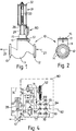
- FIGS 1 and 2 show a valve 10 generally similar to a severe service valve sold under the Registered Trade Mark “DRAG” whose principal features have been disclosed in US patents 3 513 684, 3 514 074 and 4 267 045.
- DRAG Registered Trade Mark
- Such valves have a valve trim cage assembly including a stack of discs adapted to provide energy losses in the fluid passing through the valve.
- “trim” is given its usual meaning in the field of automatic process control valves, and applies to those internal parts which contact the fluid flow and are responsible for controlling said flow. Such parts include the plug, seating, washers, cages, stems and the like.
- DRAG valves in various forms have been effectively used in the past for high pressure reduction in liquid or gas flow streams with minimal cavitation and associated vibrations and damage resulting from the special cage trim and associated design of the valve.
- a typical stack of discs for such valves is as illustrated in US Patent 4 267 045.
- valve 10 has a body 11, typically cast in special steel and made in accordance with Pressure Class 600 ANSI.
- Body 11 and all the other equipment associated with the valve has a maximum allowable fluid temperature of 225 °F (107 °C) and is subject to a hydro test pressure of 2225 PSIG.
- Valve 10 is typically located in a by-pass line of a high pressure pumped crude oil main pipeline. There could be several such valves 10 in parallel by-pass lines and their outlets would be designed to be dumped into associated tanks, pipelines or other containment devices.
- Body 11 carries an associated fluid inlet flange 12 and fluid outlet flange 13. These flanges 12 and 13 are adapted by means of bolt holes 14 to be attached to elements of the oil pipeline or by-pass line which is not illustrated.
- a bonnet 15 is adapted to be held to body 11 by means of bonnet studs 16 and bonnet securing nuts 17.
- body 11 carries an annular seal seat 18 together with an associated annular seal 19.
- An annular disc stack 20 together with annular disc stack spacer 21 are located directly above seal 19 and are held in place by bonnet 15.
- a cylindrical plug 22 with a hollow interior 23 is movable vertically upwards and downwards inside disc stack 20 from a closed position in contact with seal seat 18, thereby making available more or less of the disc stack 20 to fluid flow.
- Plug 22 is carried by stem 24 which extends vertically upwards on the central axis of plug 22.
- Stem 24 has a circular cross-section passageway 25 along its axis which is open at both ends.
- Plug 22 also has a number of axially directed passageways 26 spaced radially outwardly of stem 24.
- passageways 26 connect the space under bonnet 15 with the plug interior 23 and are designed to provide equal pressure on each side of plug 22. This pressure balancing significantly reduces the force required for actuation.
- An annular balance seal 46 is located around plug 22 to prevent leakage along the exterior of plug 22. For service up to 450 °F (232 °C) a self-energising fluorocarbon balance seal is used.
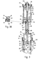
- Arrows 27 show the direction of crude oil flow through the valve (although in Figure 3 the valve is actually shown in a closed position) and it can be seen that the space inside bonnet 15 is connected with the downstream side of valve 10.
- Stem 24 carries a co-axial hollow stem extension 36 at its upper end.
- Stem extension 36 is of generally cylindrical shape and has affixed to its exterior a piston 37 moveable within a cylinder 28.
- Piston 37 carries piston seals 38 at its upper and lower edges which seal with the inside wall of cylinder 28.
- Piston seals 38 typically Teflon (Registered Trade Mark) self-energising rings so as to minimize friction.
- Cylinder 28 is sealed and located at its lower most portion in the upper most part of bonnet 15. At its uppermost portion it locates in and is sealed to a bottom end plate 30 of a spring housing 31 which extends further vertically above the stem extension 36.
- Cylinder 28 is held rigidly in place by means of cylinder studs 29 which extend parallel to and externally of cylinder 28 and which are threadedly secured in the uppermost surface of bonnet 15. Cylinder studs 29 pass through the bottom end plate 30 and are held in place by cylinder stud nuts 32.
- the spring housing 31 is a cylindrical enclosure for a helical compression spring 43.
- Spring housing 31 terminates at its upper end in top end plate 35, through which pass spring housing retaining bolts 33 which surround the cylindrical spring housing 31.
- Spring housing retaining bolts 33 pass respectively through the bottom end plate 30 and the top end plate 35 and are secured by spring housing retaining nuts 34.
- a hollow spring stem 39 extends vertically within the lower part of helical spring 43 and forms a co-axial continuation of hollow stem extension 36.
- the external diameters of spring stem 39, stem extension 36 and stem 24 are identical.
- Helical spring 43 surrounding spring stem 39 is carried at its lower end by bottom spring seat 41 and at its upper end by top spring seat 42.
- Spring stem 39 is open at its upper end into the hollow interior of spring adjusting screw 40 which extends through the top end plate 35 and is associated with a spring compression setting assembly 44 which is located above and outside top end plate 35.
- a proximity switch 45 is provided on bottom end plate 30 for sensing remotely eg via an electrical signal whether valve 10 is closed or not.
- valve body 11 As seen in Figure 3 a number of fluid entry and exit ports are provided in valve body 11, its associated bonnet 15 and the principal actuator gear located above valve 10.
- an upstream fluid tapping 50 In the upper part of body 11 on the upstream side of the valve is an upstream fluid tapping 50. As seen in Figure 1 this connects with a control fluid line 51 which in turn connects to a fluid control circuit 80 which is bolted onto bonnet 15 and also secured to the bottom end plate 30 of spring housing 31.
- fluid control tappings in the uppermost part of bonnet 15. These are shown as passageway 53 which communicates with the lower interior of cylinder 28 and passageway 55 which communicates with the interior of bonnet 15.
- a further passageway 54 is provided in bottom end plate 30 and communicates with the upper interior of cylinder 28.
- valve 10 The control equipment associated with valve 10 and its principal actuation equipment is shown within dashed line 80 in Figure 4.
- the control circuit 80 has no external power supply and is actuated solely by changes in pressure from the crude oil within the pipeline connected to valve 10.
- Line 60 is connected to the main pipeline at its closest point to valve 10 by means of a two inch line so as to provide as small a pressure drop as is practical between the main pipeline tapping and valve 10.
- Fluid in line 60 may pass through valve 61 which is a media filter and isolation valve and through a further isolation valve 62 before entering a pilot operated three-way valve 63.
- Valve 63 is set for actuation at 50 PSI decreasing, and the actuation is by way of pilot line 68 responding to changes in line pressure in line 60.
- a by-pass line 64 (to provide a dual or redundant filter system for on-line maintenance purposes) which also has an isolation/media filter valve 65 and isolation valve 66 before being connected via line 67 back into line 60.
- the outlet port of valve 63 is connected via line 69 to passageway 53 in the bonnet 15 of valve 10.
- line 70 which continues to a pressure reducing regulator 52.
- Valve 52 is a Series 9000 valve manufactured by Keane Controls of Anaheim, California, the salient features of which will be described later in this specification.
- spur 71 from line 70 which serves to actuate valve 52.
- valve 63 When or if supply line 60 to 3-way valve 63 breaks, the supply line is then line 51. If the pressure in line 60 drops below 50 psi, valve 63 will select line 51. A check valve, or non-return valve, 99 will block any leakage through line 60.
- Valve 52 has fluid outlet lines 72 and 75.
- Line 72 passes via a back pressure regulator 73 and line 74 to passageway 55 in bonnet 15 in valve 10.
- An outlet of valve 52 is thus connected to the downstream side of valve 10 since the space inside bonnet 15 is at downstream condition.
- Back pressure regulator 73 is pilot operated by change in pressure in line 72 and is typically set for actuation at 520 PSI. Regulator 73 must be set at a pressure above the maximum outlet pressure of valve 10 and below the maximum pipeline surge pressure.
- the other exit line 75 from valve 52 passes via a one way flow regulator 76 to passage 54 in the bottom end plate 30 of spring housing 31 of valve 10.
- Flow regulator 76 incorporates a speed control valve set as variable over a range of 4 to 30 seconds.
- Line 75 is thus connected to the space within cylinder 28 and acts on the uppermost side of piston 37.
- FIG. 5 shows valve 52, a pressure reducing regulator, in more detail.
- Regulator 52 is a Series 9000 Keane valve in which the compression spring 88 has been selected for a specific range of pipeline upset pressures, in this instance, 824 to 854 psi.
- the spring has a range of 800 to 850 psi and its final setting is to be determined by test. It is estimated that the setting will be 810 PSI increasing for this application.
- the valve is otherwise a standard valve.
- regulator spring 88 By force transmitted through spring seat 89, ball 90, regulator piston 91 and end member 92, regulator spring 88 holds stem 93 and associated spool 85 with spool 85 in its furthermost position towards the right as seen in Figure 5.
- Associated with spool 85 are seats 86 and 87. With spool 85 in its furthest right position, spool 85 engages against seat 86.
- Regulator 52 has three ports connecting with the space associated with spool 85. As seen in Figure 4, port 82 connects with line 70, port 83 connects with line 75 and port 84 connects with line 72. Line 71 connects with port 81 which provides for pilot actuation of regulator 52.
- Valve 10 thus starts to open at 824 psi and is fully open at 854 psi. Regulator 52 proportions the fluid flow over this range, reducing the pressure from above piston 37 proportional to the upset.
- downstream pressure is present throughout hollow stem 24, stem extension 26, spring stem 39 and within the hollow interior of spring adjusting screw 40 which forms a cylinder within which spring stem 39 can move. No matter what the position of the plug 22 in its axial movement, the presence of downstream pressure acting on surfaces in these items results in a balancing effect upon the stem.
- a further alternative arrangement to providing valve stem balancing means would be to run an external line out of bonnet 15 into the spring adjusting screw and cylinder 40, such line transmitting fluid pressure from one region to the other. Downstream pressures may vary from 5 to over 400 PSI depending upon downstream conditions.
- regulator 52 with spool 85 capable of movement between the position shown in Figure 5 and the position shown in Figure 5A against 810 PSI spring loading of this valve, permits smooth and effective operation of the piston 37 and cylinder 28 device which in turn enables plug 22 to be withdrawn from valve 10 with minimum risk of violent vibration and cavitation.
- the invention also permits effective modulated control of surging without any external power source.
Landscapes
- Engineering & Computer Science (AREA)
- Physics & Mathematics (AREA)
- General Engineering & Computer Science (AREA)
- Geology (AREA)
- Fluid Mechanics (AREA)
- Mining & Mineral Resources (AREA)
- Life Sciences & Earth Sciences (AREA)
- Geochemistry & Mineralogy (AREA)
- Environmental & Geological Engineering (AREA)
- Automation & Control Theory (AREA)
- General Life Sciences & Earth Sciences (AREA)
- General Physics & Mathematics (AREA)
- Power Engineering (AREA)
- Mechanical Engineering (AREA)
- Safety Valves (AREA)
- Control Of Fluid Pressure (AREA)
- Fluid-Pressure Circuits (AREA)
- Details Of Valves (AREA)
- Valve Device For Special Equipments (AREA)
Applications Claiming Priority (2)
| Application Number | Priority Date | Filing Date | Title |
|---|---|---|---|
| US73161791A | 1991-07-17 | 1991-07-17 | |
| US731617 | 1991-07-17 |
Publications (3)
| Publication Number | Publication Date |
|---|---|
| EP0523954A2 true EP0523954A2 (fr) | 1993-01-20 |
| EP0523954A3 EP0523954A3 (fr) | 1993-03-03 |
| EP0523954B1 EP0523954B1 (fr) | 1995-02-08 |
Family
ID=24940264
Family Applications (1)
| Application Number | Title | Priority Date | Filing Date |
|---|---|---|---|
| EP92306425A Expired - Lifetime EP0523954B1 (fr) | 1991-07-17 | 1992-07-14 | Soupape antibélier |
Country Status (7)
| Country | Link |
|---|---|
| EP (1) | EP0523954B1 (fr) |
| JP (1) | JP2588341B2 (fr) |
| AT (1) | ATE118262T1 (fr) |
| AU (1) | AU647942B2 (fr) |
| CA (1) | CA2074010C (fr) |
| DE (1) | DE69201364T2 (fr) |
| ES (1) | ES2068006T3 (fr) |
Family Cites Families (11)
| Publication number | Priority date | Publication date | Assignee | Title |
|---|---|---|---|---|
| DE7135776U (de) * | 1971-12-09 | Sasserath H & Co Kg | Druckmindererventil | |
| US3331586A (en) * | 1965-10-20 | 1967-07-18 | Eugene H Primoff | Device for loosening a window sash from the frame |
| US3331583A (en) | 1966-06-23 | 1967-07-18 | Elizabeth N Willis | Balanced shut-off valve |
| US3514074A (en) * | 1968-05-06 | 1970-05-26 | Richard E Self | High energy loss fluid control |
| BG22146A1 (fr) * | 1975-06-09 | 1977-05-20 | ||
| US4068683A (en) * | 1975-09-09 | 1978-01-17 | Control Components, Inc. | High energy loss device |
| US4167262A (en) * | 1976-10-12 | 1979-09-11 | Hunt Valve Co., Inc. | Pilot actuated valve |
| US4172466A (en) * | 1977-07-01 | 1979-10-30 | Target Rock Corporation | Self-actuated pilot-controlled safety valve |
| US4397331A (en) * | 1978-09-29 | 1983-08-09 | Honeywell Inc. | Fluid flow control valve with maximized noise reduction |
| US4267045A (en) * | 1978-10-26 | 1981-05-12 | The Babcock & Wilcox Company | Labyrinth disk stack having disks with integral filter screens |
| JPS6121484A (ja) * | 1984-05-21 | 1986-01-30 | Nippon Kousou Kk | スクリ−ンバルブおよび抵抗附与装置 |
-
1992
- 1992-07-14 ES ES92306425T patent/ES2068006T3/es not_active Expired - Lifetime
- 1992-07-14 DE DE69201364T patent/DE69201364T2/de not_active Expired - Fee Related
- 1992-07-14 EP EP92306425A patent/EP0523954B1/fr not_active Expired - Lifetime
- 1992-07-14 AT AT92306425T patent/ATE118262T1/de not_active IP Right Cessation
- 1992-07-15 AU AU19698/92A patent/AU647942B2/en not_active Ceased
- 1992-07-16 CA CA002074010A patent/CA2074010C/fr not_active Expired - Fee Related
- 1992-07-17 JP JP4191039A patent/JP2588341B2/ja not_active Expired - Fee Related
Also Published As
| Publication number | Publication date |
|---|---|
| ATE118262T1 (de) | 1995-02-15 |
| EP0523954B1 (fr) | 1995-02-08 |
| CA2074010C (fr) | 1997-12-23 |
| AU647942B2 (en) | 1994-03-31 |
| EP0523954A3 (fr) | 1993-03-03 |
| ES2068006T3 (es) | 1995-04-01 |
| JP2588341B2 (ja) | 1997-03-05 |
| CA2074010A1 (fr) | 1993-01-18 |
| DE69201364D1 (de) | 1995-03-23 |
| AU1969892A (en) | 1993-01-21 |
| DE69201364T2 (de) | 1995-06-22 |
| JPH05187568A (ja) | 1993-07-27 |
Similar Documents
| Publication | Publication Date | Title |
|---|---|---|
| US5348036A (en) | Automatic control valve | |
| US4485843A (en) | Variable pressure relief and control valve | |
| EP0247716B1 (fr) | Système de sûreté de détente pour des soupapes de contrôle ou de purge | |
| JPH08109974A (ja) | 過流防止弁 | |
| US6161570A (en) | Pilot-operated relief valve | |
| US5269347A (en) | Fluid pressure isolator apparatus | |
| US3298389A (en) | Pressure balanced valve | |
| US20040129321A1 (en) | Double valve | |
| EP3147594B1 (fr) | Vanne pour un système de réfrigération | |
| US4453561A (en) | Check valve assembly for use in backflow preventers or the like | |
| US3477456A (en) | Valve | |
| US3930518A (en) | Valves | |
| USRE29322E (en) | Valve and actuator assembly | |
| US4490836A (en) | Shut-off valve | |
| EP1592906B1 (fr) | Soupape de commande guidee par une tige et sans douille | |
| EP0189526B1 (fr) | Robinet/vanne unidirectionnel/bidirectionnel | |
| US5226444A (en) | Surge relief valve | |
| EP0523954B1 (fr) | Soupape antibélier | |
| GB1593890A (en) | Fluid pressure responsive valve | |
| WO2017019215A1 (fr) | Vanne d'arrêt automatique pour une conduite | |
| US4672995A (en) | Redundant pilot valve control system | |
| US4519416A (en) | Safety connection connecting a vessel containing a gas under pressure to a discharge system | |
| US3021866A (en) | Safety control system for fluid distribution and apparatus | |
| US3443582A (en) | Pressure control valve | |
| EP0414418B1 (fr) | Soupape de commande d'écoulement |
Legal Events
| Date | Code | Title | Description |
|---|---|---|---|
| PUAI | Public reference made under article 153(3) epc to a published international application that has entered the european phase |
Free format text: ORIGINAL CODE: 0009012 |
|
| PUAL | Search report despatched |
Free format text: ORIGINAL CODE: 0009013 |
|
| 17P | Request for examination filed |
Effective date: 19921029 |
|
| AK | Designated contracting states |
Kind code of ref document: A2 Designated state(s): AT BE CH DE ES FR GB IT LI NL SE |
|
| AK | Designated contracting states |
Kind code of ref document: A3 Designated state(s): AT BE CH DE ES FR GB IT LI NL SE |
|
| 17Q | First examination report despatched |
Effective date: 19940725 |
|
| GRAA | (expected) grant |
Free format text: ORIGINAL CODE: 0009210 |
|
| AK | Designated contracting states |
Kind code of ref document: B1 Designated state(s): AT BE CH DE ES FR GB IT LI NL SE |
|
| PG25 | Lapsed in a contracting state [announced via postgrant information from national office to epo] |
Ref country code: LI Effective date: 19950208 Ref country code: CH Effective date: 19950208 Ref country code: BE Effective date: 19950208 Ref country code: AT Effective date: 19950208 |
|
| REF | Corresponds to: |
Ref document number: 118262 Country of ref document: AT Date of ref document: 19950215 Kind code of ref document: T |
|
| REF | Corresponds to: |
Ref document number: 69201364 Country of ref document: DE Date of ref document: 19950323 |
|
| REG | Reference to a national code |
Ref country code: ES Ref legal event code: FG2A Ref document number: 2068006 Country of ref document: ES Kind code of ref document: T3 |
|
| ET | Fr: translation filed | ||
| ITF | It: translation for a ep patent filed | ||
| PG25 | Lapsed in a contracting state [announced via postgrant information from national office to epo] |
Ref country code: SE Effective date: 19950508 |
|
| REG | Reference to a national code |
Ref country code: CH Ref legal event code: PL |
|
| PLBE | No opposition filed within time limit |
Free format text: ORIGINAL CODE: 0009261 |
|
| STAA | Information on the status of an ep patent application or granted ep patent |
Free format text: STATUS: NO OPPOSITION FILED WITHIN TIME LIMIT |
|
| 26N | No opposition filed | ||
| REG | Reference to a national code |
Ref country code: GB Ref legal event code: IF02 |
|
| PGFP | Annual fee paid to national office [announced via postgrant information from national office to epo] |
Ref country code: FR Payment date: 20020621 Year of fee payment: 11 |
|
| PGFP | Annual fee paid to national office [announced via postgrant information from national office to epo] |
Ref country code: GB Payment date: 20020712 Year of fee payment: 11 |
|
| PGFP | Annual fee paid to national office [announced via postgrant information from national office to epo] |
Ref country code: NL Payment date: 20020715 Year of fee payment: 11 |
|
| PGFP | Annual fee paid to national office [announced via postgrant information from national office to epo] |
Ref country code: DE Payment date: 20020724 Year of fee payment: 11 |
|
| PGFP | Annual fee paid to national office [announced via postgrant information from national office to epo] |
Ref country code: ES Payment date: 20020809 Year of fee payment: 11 |
|
| PG25 | Lapsed in a contracting state [announced via postgrant information from national office to epo] |
Ref country code: GB Free format text: LAPSE BECAUSE OF NON-PAYMENT OF DUE FEES Effective date: 20030714 |
|
| PG25 | Lapsed in a contracting state [announced via postgrant information from national office to epo] |
Ref country code: ES Free format text: LAPSE BECAUSE OF NON-PAYMENT OF DUE FEES Effective date: 20030715 |
|
| PG25 | Lapsed in a contracting state [announced via postgrant information from national office to epo] |
Ref country code: NL Free format text: LAPSE BECAUSE OF NON-PAYMENT OF DUE FEES Effective date: 20040201 |
|
| PG25 | Lapsed in a contracting state [announced via postgrant information from national office to epo] |
Ref country code: DE Free format text: LAPSE BECAUSE OF NON-PAYMENT OF DUE FEES Effective date: 20040203 |
|
| GBPC | Gb: european patent ceased through non-payment of renewal fee |
Effective date: 20030714 |
|
| PG25 | Lapsed in a contracting state [announced via postgrant information from national office to epo] |
Ref country code: FR Free format text: LAPSE BECAUSE OF NON-PAYMENT OF DUE FEES Effective date: 20040331 |
|
| NLV4 | Nl: lapsed or anulled due to non-payment of the annual fee |
Effective date: 20040201 |
|
| REG | Reference to a national code |
Ref country code: FR Ref legal event code: ST |
|
| REG | Reference to a national code |
Ref country code: ES Ref legal event code: FD2A Effective date: 20030715 |
|
| PG25 | Lapsed in a contracting state [announced via postgrant information from national office to epo] |
Ref country code: IT Free format text: LAPSE BECAUSE OF NON-PAYMENT OF DUE FEES Effective date: 20050714 |