EP0524302B1 - Verfahren und Vorrichtungen zum Entkernen von Gussstücken - Google Patents
Verfahren und Vorrichtungen zum Entkernen von Gussstücken Download PDFInfo
- Publication number
- EP0524302B1 EP0524302B1 EP92906406A EP92906406A EP0524302B1 EP 0524302 B1 EP0524302 B1 EP 0524302B1 EP 92906406 A EP92906406 A EP 92906406A EP 92906406 A EP92906406 A EP 92906406A EP 0524302 B1 EP0524302 B1 EP 0524302B1
- Authority
- EP
- European Patent Office
- Prior art keywords
- alternative
- balancing
- plate
- movement
- clamping plate
- Prior art date
- Legal status (The legal status is an assumption and is not a legal conclusion. Google has not performed a legal analysis and makes no representation as to the accuracy of the status listed.)
- Expired - Lifetime
Links
- 238000000034 method Methods 0.000 title claims description 31
- 238000005266 casting Methods 0.000 title abstract description 9
- 239000002775 capsule Substances 0.000 claims description 17
- 230000000694 effects Effects 0.000 claims description 9
- 230000001788 irregular Effects 0.000 claims description 9
- 239000004576 sand Substances 0.000 claims description 8
- 230000008030 elimination Effects 0.000 claims description 6
- 238000003379 elimination reaction Methods 0.000 claims description 6
- 230000005484 gravity Effects 0.000 claims description 5
- 238000005488 sandblasting Methods 0.000 claims description 2
- 238000003723 Smelting Methods 0.000 claims 2
- 238000002485 combustion reaction Methods 0.000 abstract description 4
- 230000010355 oscillation Effects 0.000 abstract 1
- 238000004140 cleaning Methods 0.000 description 8
- 230000035939 shock Effects 0.000 description 4
- 238000005194 fractionation Methods 0.000 description 3
- 230000000903 blocking effect Effects 0.000 description 2
- 230000003628 erosive effect Effects 0.000 description 2
- 239000002245 particle Substances 0.000 description 2
- 241001508691 Martes zibellina Species 0.000 description 1
- 230000006978 adaptation Effects 0.000 description 1
- 230000001464 adherent effect Effects 0.000 description 1
- 239000003638 chemical reducing agent Substances 0.000 description 1
- 238000007599 discharging Methods 0.000 description 1
- 239000000428 dust Substances 0.000 description 1
- 239000012530 fluid Substances 0.000 description 1
- 239000012634 fragment Substances 0.000 description 1
- 238000013467 fragmentation Methods 0.000 description 1
- 238000006062 fragmentation reaction Methods 0.000 description 1
- 210000003127 knee Anatomy 0.000 description 1
- 239000007788 liquid Substances 0.000 description 1
- 238000004519 manufacturing process Methods 0.000 description 1
- 238000000465 moulding Methods 0.000 description 1
- 230000035515 penetration Effects 0.000 description 1
- 230000000750 progressive effect Effects 0.000 description 1
- 230000001737 promoting effect Effects 0.000 description 1
Images


Classifications
-
- B—PERFORMING OPERATIONS; TRANSPORTING
- B22—CASTING; POWDER METALLURGY
- B22D—CASTING OF METALS; CASTING OF OTHER SUBSTANCES BY THE SAME PROCESSES OR DEVICES
- B22D29/00—Removing castings from moulds, not restricted to casting processes covered by a single main group; Removing cores; Handling ingots
- B22D29/001—Removing cores
- B22D29/005—Removing cores by vibrating or hammering
Definitions
- the invention relates to a method and a device for cleaning casting cores for foundry parts.
- the object of the present invention is to remedy these drawbacks.
- This invention solves the problem consisting of defining a process and creating devices with which kernels can be not only fragmented, but also totally disaggregated, while causing an eroding effect takeoff of all sand particles, before complete evacuation by gravity in a single phase, preferably without repositioning of the part on its support.
- the first two operations of the method according to the invention allow to obtain the total disintegration of the nucleus, the second operation, namely alternative balancing of the workpiece, further enabling a certain sandblasting effect of the workpiece molded.
- alternative balancing results from the combination of a reciprocating longitudinal movement an alternative transverse movement.
- the reciprocating transverse motion is applied in a parallel plane to the one in which the longitudinal movement is applied.
- the alternative transverse movement is applied in a perpendicular plane to the one in which the longitudinal movement is applied.
- the balancing of the work is performed with an amplitude and an adjustable frequency respectively from 0 to 10 cm and from 0 to 85 Hz.
- the rocking of the piece is performed in combination with the take-up of a clearance J, introducing an additional inertial effect on the sandy mass.
- the amplitude and frequency of the swinging of the piece varies, swing course, according to rules determined according to the internal architecture of the room and the size of the cavities.
- the frequency of rocking is irregular and random.
- a device for applying the basic method according to the invention is characterized in that the high frequency shocks are applied directly on the workpiece using a pneumatic hammer, fixed on a support integral with a frame, arranged so as to strike directly the workpiece by passing the hammer through an orifice formed for this purpose in a fixed support plate, against which the workpiece is held in place by a clamping plate and a chamber cylinder, supplied with low pressure, which constitutes the air cushion, in that the swinging of the part, which takes place according to a horizontal reciprocating movement is obtained through a receiver, comprising the support plate, the clamping plate and the clamping cylinder, connected to the frame vertically by four connecting rods and horizontally by a connecting rod and a double eccentric, rotated by means of a gear motor, and in this that the elimination of sand by gravity is obtained by maintaining in position vertical of the part, by abutting it against a mechanical stop secured to the support plate.
- the receiver preferably consists of two side plates, swan neck shaped, connected together by the support plate and by a connecting plate, supporting the pneumatic cylinder with chamber bearing, on the one hand, against the connection plate and against the clamping plate mounted by means of slides on four slides connecting the support plate to the connection plate, perpendicular to them.
- the vertical connecting rods are connected to the side plates via elastic joints.
- the horizontal connecting rod is connected to the connection plate via of a screed.
- the receiver is fitted with a workpiece box, mounted with a certain clearance between the connection plate and the support plate, supported by four vertical rods fixed against the internal wall side plates by means of elastic articulation, or directly on the chassis by the same means.
- two receivers are mounted on the same frame, both on the other a unique double eccentric, thus ensuring the balancing simultaneous two pieces in line with two hammers tires arranged at each end of the frame.
- the transverse reciprocating movement is obtained through a crankshaft connected to a workpiece holder by at least a connecting rod in that said work-holding capsule is supported by a built by means of four links articulated in planes perpendicular to the crankshaft and in that the frequency of swaying alternative is made irregular and random by variation corresponding to the speed of rotation of the drive motor crankshaft.
- the transverse reciprocating movement is obtained in a perpendicular plane longitudinal movement via a crankshaft connected to the workpiece holder by at least one bearing fixed under the latter, and springs, interposed vertically between the capsule workpiece and the frame, and in that the frequency of the alternating swing is made irregular and random by corresponding variation the rotational speed of the crankshaft drive engine.
- crankshaft is arranged in the longitudinal median plane of the capsule workpiece carrier while the springs are divided into two rows arranged symmetrically with respect to the crankshaft.
- the reciprocating longitudinal movement and the reciprocating transverse movement are combined in a same movement ensuring the overall alternative swing by through two crankshafts arranged vertically between a frame and a workpiece holder support, and in that the frequency of alternative swing is made irregular and random by variation corresponding to the speed of rotation of the drive motor crankshafts.
- the speed variation of the drive motor of the eccentric or the crankshaft is obtained through a electronic dimmer controlled.
- the advantages obtained with this invention consist essentially of in that hollow rooms, of complex architecture, such as internal combustion engine cylinder heads, can be made by molding, without risk of difficulty in removing all of the core, while improving the surface condition of the walls by sanding effect, thus promoting the subsequent flow of liquid fluids or gaseous, intended to circulate in the cavities formed inside of the room, according to a very complex architecture.
- Figures 1 and 2 show a part 1, mounted on a device for fractioning and discharging the casting core of foundry parts according to the invention, comprising a pneumatic hammer 20 with hammer 21, fixed on a support 3 integral with a frame 4 arranged so as to strike the part 1 directly by passing the hammer 21 through an orifice 401, formed, for this purpose, in a fixed support plate 40 with vertical stop 402, against which the part 1 is held by means of a clamping plate 41 subjected to the action of a chamber cylinder 50, supplied with low pressure, constituting an air cushion; said support plate 40 and said clamping plate 41 are part of a receiver 60, connected to the frame 4 vertically by four connecting rods 70 with elastic articulation 71 and horizontally by a connecting rod 72 connected, on the one hand, to a double eccentric 80 driven by a variable speed motor reducer 81 and, on the other hand, via a yoke 431 to a connection plate 43 supporting the chamber cylinder 50 , connecting transversely, in combination with
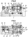
- FIGS. 3 and 4 represent a part mounted with a clearance J on a device for fractioning and evacuating the casting core, which differs from that shown in FIGS. 1 and 2 only by the presence of sleeve 413, forming a stop, on the slides 412, between the support plate 40 and the clamping plate 41.
- the parts 1 can be directly introduced from above, or, optionally, laterally, into the space thus formed between the two plates 40, 41, it being understood that the stop 402 existing on the support plate 40 limits the penetration of the part 1 in this space, without the need to use any blocking system. Note that on certain flat parts, the parts can be clamped directly, without interposing the clamping plate 41.
- the receiver 60 then being brought at the end of the stroke to the pneumatic hammer 20, by controlled action on the double eccentric 80 via the gear motor 81, the operation can then begin, since the hammer 21 of the pneumatic hammer 20 can - strike directly on the part, passing through the orifice 401 provided for this purpose.
- These hammering actions at high frequency, on the resonant assembly, consisting of the part 1 with its clamping plate 41 and of the chamber cylinder 50 at low pressure, cause, in the vicinity of the natural frequency of resonance of the system, a fractionation and takeoff of the nucleus. This resonance phenomenon can be controlled by acting on the inflation pressure of the chamber cylinder 50 and on the frequency of hammering.
- the sand resulting from the disintegration of the core flows by gravity between the side plates 61, 62 of said receiver and the side members of the frame 4.
- This sand can be discharged at the gradually by a conveyor belt.
- the swing frequency and its amplitude can, respectively, be adjusted, by action on a speed regulator and by action on the double eccentric.
- the disintegration action of the core fragments may be further increased, by providing a clearance J between the so-called clamping plate 41 and the part 1, by adding a sleeve 413 of appropriate length on the slides 412 ( Figures 3 and 4), or, as shown in Figures 5 and 6, by means of two jacks 55 and 56, mounted in opposition and passing through the connecting plate 43, the rod 551 of one of which is connected to the yoke 431 and whose rod 561 on the other comes to bear against the clamping plate 41, or directly against the part 1, to ensure, therein, a clearance J controlled in the horizontal plane; the clamping plate 41 then being secured to its slides by means of locking devices, incorporated in the slides 411.
- the jack 55 ensures the approach of the clamping plate as a function of the thickness of the part and the jack 56 only provides clearance J.
- this arrangement which corresponds to FIGS. 3 to 6, makes it possible to further increase the effect of inertia and, consequently, the collision between the pieces of core; it also facilitates the evacuation of sand, when dealing with parts with fairly complex internal architecture.
- the part 1 is fixed in the receiver 60 by means of a housing 90, mounted with clearance between the connecting plate 43 and the plate support 40, made integral with the side plates 61 and 62 of the receiver, or of the chassis (as shown in the figures), by means of four vertical links 73 fixed by means of elastic articulation 71.
- the part is locked against one of the short sides 91 of the housing, located towards the pneumatic hammer 20, by means of a chamber cylinder 50 bearing against the small opposite side 92 of said housing 90, with or without interposition, d 'a clamping plate 41 . It is thus possible to obtain a combined rocking of the part 1 by means of the receiver 60 and of the housing 90, by accompanying the latter with shocks due to the clearance provided between the housing and the connection plates 43 and d 'support 40.
- Figures 12 to 14 show a frame 1000,190 supporting a workpiece capsule 200 or a capsule support 1000 by means of links 500, springs 700 or crankshafts 180, actuated respectively by a crankshaft 300, one or more connecting rods 400 and a drive motor 600.
- the workpiece capsule 200 is connected to the frame 1000 by means of links 500, which can be common with those allowing the longitudinal swing, provided that their articulations are designed accordingly. (knee pads or double axis of articulation); the lateral swinging being ensured by the connecting rod 400 , driven by a reciprocating movement by means of the crankshaft 300. It is obvious, for the skilled person, that the frequency of the alternating swinging thus created and maintained by the engine 600, could be made random by simple random variation of the speed of rotation of said motor 600 ; which can be easily obtained by means of an electronic variator, the control of which is ensured accordingly.
- the workpiece capsule 200 is connected to the frame 1000 by means of the crankshaft 300, in direct engagement, on the underside of said capsule 200, and two rows of springs 700, arranged on each side of the crankshaft and ensuring the return to the vertical position of the capsule 200, while creating, with this, a vibrating system, which, combined with a random variation of the rotation speed of the crankshaft, obtained as indicated in the example above, will generate and maintain a random alternating swing of said workpiece carrier capsule 200.
- the longitudinal swing can be obtained by alternating sliding of the bearing 201, connecting the workpiece capsule 200 to the crankshaft 300, on the crankpin of said crankshaft, provided that the length thereof is predetermined accordingly to provide sufficient sliding freedom.
- the longitudinal swing and the transverse swing of the support 100 are combined in the circular movement of the crank pin 181 of the crankshafts 180 relative to the drive shaft 182 of these latter.
- the swing thus obtained can be made irregular and random, in this case too, by varying the speed of rotation of the crankshaft drive motor, using the means already mentioned in the other examples.
- the frequency of the longitudinal swing can be made, it also, random by random variation of the rotation speed of the motor assigned to this function.
- the method and the device according to the invention mainly concern the cleaning of the internal combustion engine cylinder heads, but nothing prevents their use for the elimination of the nucleus other foundry pieces with the same internal complexity, subject to minor adaptations.
Landscapes
- Engineering & Computer Science (AREA)
- Mechanical Engineering (AREA)
- Percussive Tools And Related Accessories (AREA)
- Control Of Motors That Do Not Use Commutators (AREA)
- Cylinder Crankcases Of Internal Combustion Engines (AREA)
- Dental Preparations (AREA)
- Organic Low-Molecular-Weight Compounds And Preparation Thereof (AREA)
- Molds, Cores, And Manufacturing Methods Thereof (AREA)
Claims (22)
- Verfahren zur Fraktionierung und Austragung des Gießkerns von Gußstücken, umfassend die nachfolgenden, nacheinander ablaufenden Operationen:Einwirkung von Stößen mit hoher Frequenz direkt auf das Stück (1), während dieses zur Erreichung der Fraktionierung des Kerns stützend gegen ein pneumatisches Polster gehalten wird,horizontales Hin- und Herpendeln des Stücks (1), um den vollständigen Zerfall des Kerns und einen Sandstrahleffekt der Innenwände des besagten Stücks (1) zu erreichen,Austragen des Sandes durch Schwerkraft, in dem Maße, wie der Kern zerfällt.
- Verfahren gemäß Anspruch 1, dadurch gekennzeichnet, daß das Hin- und Herpendeln aus der Verbindung einer Pendelbewegung in Längsrichtung zu einer Pendelbewegung in Querrichtung resultiert.
- Verfahren gemäß Anspruch 2, dadurch gekennzeichnet, daß die Pendelbewegung in Querrichtung in einer parallelen Ebene zu der Ebene angewendet wird, in der die Bewegung in Längsrichtung angewendet wird.
- Verfahren gemäß Anspruch 2, dadurch gekennzeichnet, daß die Pendelbewegung in Querrichtung in einer senkrechten Ebene zu der Ebene angewendet wird, in der die Bewegung in Längsrichtung angewendet wird.
- Verfahren gemäß Anspruch 1 oder 2, dadurch gekennzeichnet, daß das Hin- und Herpendeln des Stücks (1) vom Nachstellen eines eine zusätzliche Trägheitswirkung auf die sandhaltige Masse einführenden Spielraums (J) begleitet wird.
- Verfahren gemäß Anspruch 1 oder 2, dadurch gekennzeichnet, daß das Pendeln des Stücks mit einer von 0 bis 10 cm einstellbaren Ausschlagweite geschieht.
- Verfahren gemäß Anspruch 1 oder 2, dadurch gekennzeichnet, daß die Ausschlagweite und die Frequenz des Pendelns in seinem Verlauf gemäß den im Hinblick auf die interne Architektur des Stücks (1) und die Abmessung der Hohlräume bestimmten Regeln variieren.
- Verfahren gemäß Anspruch 7, dadurch gekennzeichnet, daß die Frequenz des Pendelns zwischen 0 und 85 Hz liegt.
- Verfahren gemäß Anspruch 1 oder 2, dadurch gekennzeichnet, daß die Frequenz des Pendelns unregelmäßig und zufällig ist.
- Vorrichtung zur Fraktionierung und Austragung des Gießkerns des Gusses von Gußstücken für die Durchführung des Verfahrens gemäß den vorigen Ansprüchen, dadurch gekennzeichnet, daß sie einen auf einer mit einem Gehäuse (4) fest verbundene Stütze (3) befestigten Druckluftbohrhammer (20) umfaßt, der derart angebracht ist, daß er das Stück direkt durch den Durchgang des Hammers (21) durch eine Öffnung (401) anschlägt, die zu diesem Zweck in einer festen Stützplatte (40) angebracht ist, gegen die das Stück (1) durch eine Spannplatte (41) und einen mit Niederdruck versorgten und ein Luftkissen bildenden Kammerzylinder (50) festgehalten wird; wobei die besagte Stützplatte (40) und die besagte Spannplatte (41) Teil einer Aufnahme (60) sind, die vertikal mit dem Gehäuse (4) durch vier Pleuel (70) und durch einen Pleuel (70) verbunden sind, der durch eine doppelte Exzenterscheibe (80) angetrieben wird, die mittels eines Getriebemotors (81) in Rotation gebracht wird; wobei das Stück (1) durch das in Anschlagbringen gegen einen mit der Stützplatte (40) fest verbundenen mechanischen Anschlag (402) in vertikaler Position gehalten wird.
- Vorrichtung gemäß Anspruch 10, dadurch gekennzeichnet, daß die Aufnahme (60) aus zwei lateralen Platten in Form von Schwanenhälsen (61, 62) besteht, die untereinander durch die Stützplatte (40) und die Verbindungsplatte (43) verbunden sind, die den pneumatischen Kammerzylinder (50) stützt, der sich einerseits an der Verbindungsplatte (43) abstützt und andererseits gegen die Spannplatte (41), die mittels Schieber (411) auf vier Laufschienen (412) aufgebaut ist, die die Stützplatte (40) senkrecht zu dieser mit der Verbindungsplatte (43) verbinden.
- Vorrichtung gemäß Anspruch 10, dadurch gekennzeichnet, daß die vertikalen Pleuel (70) mit den lateralen Platten (61, 62) durch elastische Gelenke verbunden sind.
- Vorrichtung gemäß Anspruch 10, dadurch gekennzeichnet, daß der horizontale Pleuel (72) mit der Verbindungsplatte (43) durch eine Abdeckung (431) verbunden ist.
- Vorrichtung gemäß Anspruch 10, dadurch gekennzeichnet, daß zwei Aufnahmen (60) auf einem und demselben Gehäuse auf jeder Seite einer einzigen doppelten Exzenterscheibe (80) angebracht sind und somit das gleichzeitige Pendeln von zwei Stücken (1) in der Anordnung von zwei pneumatischen Druckluftbohrhammern (20) gewährleisten, die jeder an einem Ende des Gehäuses angebracht sind.
- Vorrichtung gemäß Anspruch 10, dadurch gekennzeichnet, daß wenn ein Spielraum (J) zwischen der Spannplatte (43) und dem Stück (1) ausgespart werden soll, dieser durch die Anbringung auf den Laufschienen (412) von Stutzen (413), deren Länge im Hinblick auf die Dicke des Stücks (1) bestimmt wird, zwischen der Stützplatte (40) und der Spannplatte (41) erhalten wird.
- Vorrichtung gemäß Anspruch 10, dadurch gekennzeichnet, daß, wenn ein Spielraum (J) zwischen der Spannplatte (41) und dem Stück (1) ausgespart werden soll, dieser durch zwei einander gegenüber angebrachte und die Verbindungsplatte (43) durchdringende Zylinder (55 und 56) erhalten wird, deren einer Stift (551) mit der Abdeckung (431) verbunden ist und deren anderer Stift (561) die Einführung des Spielraums (J) zwischen dem Stück (1) und der Spannplatte (41) kontrolliert; wobei diese letztere (41) anschließend mit ihren Laufschienen (412) durch auf der Höhe der Schieber (411) durchgeführte Blockierung fest verbunden wird.
- Vorrichtung gemäß Anspruch 10, dadurch gekennzeichnet, daß das Stück (1) durch eine mit Zwischenraum zwischen der Verbindungsplatte (43) und der Stützplatte (40) angebrachte, im Verhältnis zu den lateralen (61 und 62) Platten der Aufnahme (60) mittels der vertikalen (73) mit elastischen Gelenken (71) versehenen Pleuel beweglich verbundenen Box (90) in der Aufnahme (60) angebracht wird; wobei das besagte Stück (1) gegen eine der kleinen Seiten (91) der sich in Richtung des Drucklufthammers (20) befindenden Box (90) mittels wenigstens eines sich gegen die entgegengesetzte Seite (92) der Box stützenden Kammerzylinders (50) bewegungsunfähig festgehalten wird.
- Vorrichtung gemäß Anspruch 10, dadurch gekennzeichnet, daß sie zur Gewährleistung der Pendelbewegung in Querrichtung eine Kurbelwelle (300) umfaßt, die durch mindestens ein Zwischenglied (400) mit einer teiletragenden Kapsel (200) verbunden ist, wobei die besagte teiletragende Kapsel (200) durch ein Tragelement (1000) mittels vier kleinen Zwischengliedern (500) gehalten wird, die in senkrechter Ebene zur Kurbelwelle (300) beweglich verbunden sind, die durch einen Motor (600) angetrieben wird, dessen Schwankung der Rotationsgeschwindigkeit es erlaubt, die Frequenz der Pendelbewegung unregelmäßig und zufällig zu machen.
- Vorrichtung gemäß Anspruch 10, dadurch gekennzeichnet, daß sie zur Gewährleistung der Pendelbewegung in Querrichtung eine Kurbelwelle (300) umfaßt, die durch mindestens ein Lager (201), das unter dieser letzteren befestigt ist, mit einer teiletragenden Kapsel (200) und mit vertikal zwischen der besagten teiletragenden Kapsel (220) und dem Tragelement (1000) eingeschalteten Federn (700) verbunden ist, wobei die Kurbelwelle (300) durch einen Motor (600) angetrieben wird, dessen Schwankung der Rotationsgeschwindigkeit es erlaubt, die Frequenz der Pendelbewegung in Querrichtung unregelmäßig und zufällig zu machen.
- Vorrichtung gemäß Anspruch 19, dadurch gekennzeichnet, daß die Kurbelwelle (300) in zentraler Ebene in Längsrichtung der teiletragenden Kapsel (200) angebracht ist, während die Federn (700) in zwei zur Kurbelwelle (300) symmetrisch angeordneten Reihen aufgeteilt sind.
- Vorrichtung gemäß Anspruch 10, dadurch gekennzeichnet, daß sie zur Gewährleistung einer in ein und derselben Bewegung kombinierten Pendelbewegung in Längsrichtung und einer Pendelbewegung in Querrichtung zwei vertikal zwischen einem Unterteil (190) und einer Auflage (100) der teiletragenden Kapsel Kurbeln (180) angebracht sind, wobei die Frequenz der Pendelbewegung durch entsprechende Schwankung der Rotationsgeschwindigkeit des Antriebsmotors der Kurbeln (180) unregelmäßig und zufällig gemacht wird.
- Vorrichtung gemaß einem der Ansprüche 10 bis 21, dadurch gekennzeichnet, daß die Schwankung der Geschwindigkeit des Antriebsmotors (81, 600) mittels eines gesteuerten elektronischen Variators erreicht wird.
Applications Claiming Priority (5)
| Application Number | Priority Date | Filing Date | Title |
|---|---|---|---|
| FR9101385 | 1991-02-07 | ||
| FR9101385A FR2672525B1 (fr) | 1991-02-07 | 1991-02-07 | Procede et dispositif de debourrage de noyaux de coulee de pieces de fonderie. |
| FR9110389A FR2680327B1 (fr) | 1991-08-14 | 1991-08-14 | Perfectionnements aux procedes et aux dispositifs de debourrage de noyaux de coulee de pieces de fonderie. |
| FR9110389 | 1991-08-14 | ||
| PCT/FR1992/000095 WO1992013663A1 (fr) | 1991-02-07 | 1992-02-04 | Procede et dispositifs de debourrage de noyaux de coulee de pieces de fonderie |
Publications (2)
| Publication Number | Publication Date |
|---|---|
| EP0524302A1 EP0524302A1 (de) | 1993-01-27 |
| EP0524302B1 true EP0524302B1 (de) | 1999-10-20 |
Family
ID=26228498
Family Applications (1)
| Application Number | Title | Priority Date | Filing Date |
|---|---|---|---|
| EP92906406A Expired - Lifetime EP0524302B1 (de) | 1991-02-07 | 1992-02-04 | Verfahren und Vorrichtungen zum Entkernen von Gussstücken |
Country Status (10)
| Country | Link |
|---|---|
| US (1) | US5460219A (de) |
| EP (1) | EP0524302B1 (de) |
| JP (1) | JP3056526B2 (de) |
| KR (1) | KR100227743B1 (de) |
| AT (1) | ATE185725T1 (de) |
| AU (1) | AU1344692A (de) |
| CA (1) | CA2079996C (de) |
| DE (1) | DE69230160T2 (de) |
| ES (1) | ES2142316T3 (de) |
| WO (1) | WO1992013663A1 (de) |
Cited By (1)
| Publication number | Priority date | Publication date | Assignee | Title |
|---|---|---|---|---|
| DE102007022043A1 (de) | 2007-05-08 | 2008-11-13 | August Mössner GmbH & Co. KG | Rüttelvorrichtung und Verfahren zum Entfernen des Kernsandes aus hohlen Gussstücken |
Families Citing this family (18)
| Publication number | Priority date | Publication date | Assignee | Title |
|---|---|---|---|---|
| FR2699840B1 (fr) * | 1992-12-28 | 1995-02-10 | Peugeot | Machine à dessabler les pièces de fonderie. |
| FR2711931B1 (fr) * | 1993-11-05 | 1996-02-09 | Dimafond | Dispositif perfectionné de débourrage de noyaux de coulée de pièces de fonderie. |
| FR2730436B1 (fr) * | 1995-02-13 | 1997-05-09 | Peugeot | Procede et dispositif pour le dessablage d'une piece de fonderie |
| IT1308141B1 (it) * | 1999-03-17 | 2001-11-29 | Fi Me S R L Societa Unipersona | Sterratore per getti di fonderia. |
| US7094476B2 (en) * | 2002-06-27 | 2006-08-22 | Asahi Tec Corporation | Surface-treated product, surface-treatment method, and surface-treatment apparatus |
| FR2850305B1 (fr) * | 2003-01-23 | 2005-03-18 | Marcel Massin | Systeme automatise de debourrage et dispositif de debourrage |
| FR2850890B1 (fr) * | 2003-02-10 | 2006-09-15 | Remi Dupuis | Dispositif de dessablage de pieces de fonderie creuses |
| CN100346906C (zh) * | 2005-03-24 | 2007-11-07 | 北京铝镁泰和铸机设备科技有限公司 | 一种分段式凸轮脱型装置及其应用方法 |
| KR101038721B1 (ko) * | 2006-03-30 | 2011-06-02 | 아사히 테크 가부시키가이샤 | 상하요동식 가공장치 |
| US7712513B1 (en) * | 2006-04-04 | 2010-05-11 | Carrier Vibrating Equipment Co. | System and method for controlling casting shakeout retention |
| JP5772488B2 (ja) * | 2011-10-19 | 2015-09-02 | 日産自動車株式会社 | 中子砂落とし方法 |
| US9109531B2 (en) | 2012-01-09 | 2015-08-18 | Honda Motor Co., Ltd. | Method for testing casting quality and apparatus therefor |
| SI24307A (sl) | 2013-03-29 | 2014-09-30 | Rc Simit D.O.O. | Vrtanje peščenih jeder iz ulitkov |
| CN103231042A (zh) * | 2013-04-25 | 2013-08-07 | 吴江市董鑫塑料包装厂 | 一种起模装置 |
| CN106001519B (zh) * | 2016-07-08 | 2018-10-02 | 芜湖永达科技有限公司 | 一种缸体震芯机 |
| JP2020102939A (ja) * | 2018-12-21 | 2020-07-02 | 日本電産株式会社 | アクチュエータ |
| KR102147091B1 (ko) * | 2019-01-11 | 2020-08-24 | 이정수 | 진동분리기 및 이를 이용한 주물 분리 시스템 |
| JP7323927B2 (ja) * | 2019-11-08 | 2023-08-09 | アピュアン株式会社 | 鋳砂除去装置、及び鋳砂除去方法 |
Family Cites Families (11)
| Publication number | Priority date | Publication date | Assignee | Title |
|---|---|---|---|---|
| US3162910A (en) * | 1961-06-26 | 1964-12-29 | Simplicity Eng Co | Apparatus for shaking out foundry flasks |
| US4185681A (en) * | 1978-06-22 | 1980-01-29 | Conveyersmith, Inc. | Ceramic knock-off apparatus for removing ceramic from investment casting molds |
| CH654230A5 (de) * | 1981-05-27 | 1986-02-14 | Werner Lueber | Vorrichtung zum entfernen des kernsandes aus guss-stuecken. |
| DE3236709A1 (de) * | 1982-10-04 | 1984-04-05 | R.S. Rösler Gleitschlifftechnik und technische Keramik GmbH, 8623 Staffelstein | Vorrichtung zur entkernung von gussteilen |
| DE3239262A1 (de) * | 1982-10-23 | 1984-04-26 | Alb. Klein Gmbh & Co Kg, 5241 Niederfischbach | Verfahren und vorrichtung zum entkernen von gussstuecken |
| IT1157143B (it) * | 1982-12-14 | 1987-02-11 | Fataluminium Spa | Dispositivo di sterratura per getti metallici cavi |
| DE3341894C1 (de) * | 1983-11-19 | 1985-03-14 | Bayerische Motoren Werke AG, 8000 München | Vorrichtung zum Entkernen von Gussstuecken durch Vibrationsschwingungen |
| US4718473A (en) * | 1985-01-25 | 1988-01-12 | General Kinematics Corporation | Vibratory stress relief apparatus |
| DE3728687A1 (de) * | 1987-08-27 | 1989-03-09 | Froelich & Kluepfel Druckluft | Verfahren und vorrichtung zum entkernen von gussstuecken |
| DE8900887U1 (de) * | 1988-01-27 | 1989-05-03 | "F. u. K." Frölich & Klüpfel Drucklufttechnik GmbH & Co KG, 5600 Wuppertal | Vorrichtung zum Entkernen von Gußstücken |
| ATE97040T1 (de) * | 1988-01-27 | 1993-11-15 | Froelich & Kluepfel Druckluft | Vorrichtung zum entkernen von gussstuecken. |
-
1992
- 1992-02-04 EP EP92906406A patent/EP0524302B1/de not_active Expired - Lifetime
- 1992-02-04 JP JP4505537A patent/JP3056526B2/ja not_active Expired - Lifetime
- 1992-02-04 AT AT92906406T patent/ATE185725T1/de not_active IP Right Cessation
- 1992-02-04 DE DE69230160T patent/DE69230160T2/de not_active Expired - Fee Related
- 1992-02-04 WO PCT/FR1992/000095 patent/WO1992013663A1/fr not_active Ceased
- 1992-02-04 US US07/934,540 patent/US5460219A/en not_active Expired - Fee Related
- 1992-02-04 AU AU13446/92A patent/AU1344692A/en not_active Abandoned
- 1992-02-04 ES ES92906406T patent/ES2142316T3/es not_active Expired - Lifetime
- 1992-02-04 KR KR1019920702456A patent/KR100227743B1/ko not_active Expired - Fee Related
- 1992-02-04 CA CA002079996A patent/CA2079996C/fr not_active Expired - Fee Related
Cited By (3)
| Publication number | Priority date | Publication date | Assignee | Title |
|---|---|---|---|---|
| DE102007022043A1 (de) | 2007-05-08 | 2008-11-13 | August Mössner GmbH & Co. KG | Rüttelvorrichtung und Verfahren zum Entfernen des Kernsandes aus hohlen Gussstücken |
| DE202007018558U1 (de) | 2007-05-08 | 2008-11-13 | August Mössner GmbH & Co. KG | Rüttelvorrichtung zum Entfernen des Kernsandes aus hohlen Gussstücken |
| EP1995002A2 (de) | 2007-05-08 | 2008-11-26 | August Moessner GmbH & Co. KG. | Rüttelvorrichtung und Verfahren zum Entfernen des Kernsandes aus hohlen Gußstücken |
Also Published As
| Publication number | Publication date |
|---|---|
| KR100227743B1 (ko) | 1999-11-01 |
| JP3056526B2 (ja) | 2000-06-26 |
| DE69230160T2 (de) | 2000-08-17 |
| WO1992013663A1 (fr) | 1992-08-20 |
| CA2079996A1 (fr) | 1992-08-08 |
| DE69230160D1 (de) | 1999-11-25 |
| ATE185725T1 (de) | 1999-11-15 |
| CA2079996C (fr) | 2000-04-25 |
| JPH05506407A (ja) | 1993-09-22 |
| US5460219A (en) | 1995-10-24 |
| ES2142316T3 (es) | 2000-04-16 |
| AU1344692A (en) | 1992-09-07 |
| EP0524302A1 (de) | 1993-01-27 |
Similar Documents
| Publication | Publication Date | Title |
|---|---|---|
| EP0524302B1 (de) | Verfahren und Vorrichtungen zum Entkernen von Gussstücken | |
| EP0652063B1 (de) | Vorrichtung zum Entkernen von Gussstücken | |
| EP0099791B1 (de) | Maschine für die Gewinnung und das Behauen von Steinblöcken,Marmor und Granit,insbesondere in Steinbrüchen | |
| FR2801236A1 (fr) | Procede et machine de grenaillage par ultrasons de pieces sur une roue | |
| EP1203637A1 (de) | Ultraschallquerstrahlhämmern der Schaufeln eines Rotors | |
| CA1041254A (en) | Method and apparatus for vibration cleaning of workpieces such as engine blocks | |
| FR2462943A1 (fr) | Machine vibrante destinee a etre montee sur un support fixe | |
| EP1594642B1 (de) | Automatische entkernungsvorrichtung und system | |
| EP4000837B1 (de) | Baumaschine mit versetzter vibrationsquelle | |
| CA2105219C (fr) | Appareil servant a deplacer des billes de sciage ou tiges d'arbre entre deux stations | |
| FR2703928A1 (fr) | Appareil pour fragmenter des objets solides. | |
| WO2007132101A1 (fr) | Procede de martelage, dispositif marteleur actionnable par un systeme vibrateur et utilisation du dispositif dans une machine de debourrage | |
| FR2672525A1 (fr) | Procede et dispositif de debourrage de noyaux de coulee de pieces de fonderie. | |
| FR2850890A1 (fr) | Dispositif de dessablage de pieces de fonderie creuses | |
| FR2970662A1 (fr) | Vilebrequin et procede de fabrication de ce vilebrequin | |
| FR2730436A1 (fr) | Procede et dispositif pour le dessablage d'une piece de fonderie | |
| FR2994396A1 (fr) | Dispositif de debourrage d'une piece de fonderie | |
| FR2680327A1 (fr) | Perfectionnements aux procedes et aux dispositifs de debourrage de noyaux de coulee de pieces de fonderie. | |
| EP0069106B1 (de) | Maschine zum Sägen von Steinblöcken | |
| FR2655281A1 (fr) | Appareil et procede pour comprimer du sable. | |
| FR3006612A1 (fr) | Dispositif vibrant du type crible a forte acceleration. | |
| BE1001531A4 (fr) | Machine de sciage a cadre vertical. | |
| FR2532580A1 (fr) | Ensemble vibrant pour le moulage d'elements notamment en beton | |
| EP2613918A1 (de) | Kette für eine gesteinsfräse und gesteinsfräse | |
| WO1995002550A1 (fr) | Dispositif vibreur pour le transport ou le tri de pieces ou de materiaux pulverulents |
Legal Events
| Date | Code | Title | Description |
|---|---|---|---|
| PUAI | Public reference made under article 153(3) epc to a published international application that has entered the european phase |
Free format text: ORIGINAL CODE: 0009012 |
|
| 17P | Request for examination filed |
Effective date: 19921002 |
|
| AK | Designated contracting states |
Kind code of ref document: A1 Designated state(s): AT DE ES FR GB IT |
|
| 17Q | First examination report despatched |
Effective date: 19970327 |
|
| GRAG | Despatch of communication of intention to grant |
Free format text: ORIGINAL CODE: EPIDOS AGRA |
|
| GRAG | Despatch of communication of intention to grant |
Free format text: ORIGINAL CODE: EPIDOS AGRA |
|
| GRAG | Despatch of communication of intention to grant |
Free format text: ORIGINAL CODE: EPIDOS AGRA |
|
| GRAH | Despatch of communication of intention to grant a patent |
Free format text: ORIGINAL CODE: EPIDOS IGRA |
|
| GRAH | Despatch of communication of intention to grant a patent |
Free format text: ORIGINAL CODE: EPIDOS IGRA |
|
| GRAA | (expected) grant |
Free format text: ORIGINAL CODE: 0009210 |
|
| AK | Designated contracting states |
Kind code of ref document: B1 Designated state(s): AT DE ES FR GB IT |
|
| PG25 | Lapsed in a contracting state [announced via postgrant information from national office to epo] |
Ref country code: GB Free format text: LAPSE BECAUSE OF FAILURE TO SUBMIT A TRANSLATION OF THE DESCRIPTION OR TO PAY THE FEE WITHIN THE PRESCRIBED TIME-LIMIT Effective date: 19991020 |
|
| REF | Corresponds to: |
Ref document number: 185725 Country of ref document: AT Date of ref document: 19991115 Kind code of ref document: T |
|
| REF | Corresponds to: |
Ref document number: 69230160 Country of ref document: DE Date of ref document: 19991125 |
|
| ITF | It: translation for a ep patent filed | ||
| PG25 | Lapsed in a contracting state [announced via postgrant information from national office to epo] |
Ref country code: ES Free format text: LAPSE BECAUSE OF NON-PAYMENT OF DUE FEES Effective date: 20000205 |
|
| PGFP | Annual fee paid to national office [announced via postgrant information from national office to epo] |
Ref country code: AT Payment date: 20000229 Year of fee payment: 9 |
|
| PGFP | Annual fee paid to national office [announced via postgrant information from national office to epo] |
Ref country code: GB Payment date: 20000306 Year of fee payment: 9 |
|
| PGFP | Annual fee paid to national office [announced via postgrant information from national office to epo] |
Ref country code: DE Payment date: 20000414 Year of fee payment: 9 |
|
| REG | Reference to a national code |
Ref country code: ES Ref legal event code: FG2A Ref document number: 2142316 Country of ref document: ES Kind code of ref document: T3 |
|
| GBT | Gb: translation of ep patent filed (gb section 77(6)(a)/1977) |
Effective date: 20000605 |
|
| PLBE | No opposition filed within time limit |
Free format text: ORIGINAL CODE: 0009261 |
|
| STAA | Information on the status of an ep patent application or granted ep patent |
Free format text: STATUS: NO OPPOSITION FILED WITHIN TIME LIMIT |
|
| PGFP | Annual fee paid to national office [announced via postgrant information from national office to epo] |
Ref country code: FR Payment date: 20000828 Year of fee payment: 8 |
|
| 26N | No opposition filed | ||
| PG25 | Lapsed in a contracting state [announced via postgrant information from national office to epo] |
Ref country code: AT Free format text: LAPSE BECAUSE OF NON-PAYMENT OF DUE FEES Effective date: 20010204 |
|
| GBPC | Gb: european patent ceased through non-payment of renewal fee |
Effective date: 20010204 |
|
| PG25 | Lapsed in a contracting state [announced via postgrant information from national office to epo] |
Ref country code: FR Free format text: LAPSE BECAUSE OF NON-PAYMENT OF DUE FEES Effective date: 20011031 |
|
| REG | Reference to a national code |
Ref country code: FR Ref legal event code: ST |
|
| PG25 | Lapsed in a contracting state [announced via postgrant information from national office to epo] |
Ref country code: DE Free format text: LAPSE BECAUSE OF NON-PAYMENT OF DUE FEES Effective date: 20011201 |
|
| REG | Reference to a national code |
Ref country code: ES Ref legal event code: FD2A Effective date: 20020603 |
|
| PG25 | Lapsed in a contracting state [announced via postgrant information from national office to epo] |
Ref country code: IT Free format text: LAPSE BECAUSE OF NON-PAYMENT OF DUE FEES;WARNING: LAPSES OF ITALIAN PATENTS WITH EFFECTIVE DATE BEFORE 2007 MAY HAVE OCCURRED AT ANY TIME BEFORE 2007. THE CORRECT EFFECTIVE DATE MAY BE DIFFERENT FROM THE ONE RECORDED. Effective date: 20050204 |
|
| PG25 | Lapsed in a contracting state [announced via postgrant information from national office to epo] |
Ref country code: FR Free format text: LAPSE BECAUSE OF NON-PAYMENT OF DUE FEES Effective date: 20000229 |