EP0524342A1 - Transducteur basé à la technologie de courant de Foucault - Google Patents
Transducteur basé à la technologie de courant de Foucault Download PDFInfo
- Publication number
- EP0524342A1 EP0524342A1 EP91112571A EP91112571A EP0524342A1 EP 0524342 A1 EP0524342 A1 EP 0524342A1 EP 91112571 A EP91112571 A EP 91112571A EP 91112571 A EP91112571 A EP 91112571A EP 0524342 A1 EP0524342 A1 EP 0524342A1
- Authority
- EP
- European Patent Office
- Prior art keywords
- flux
- transducer according
- transducer
- plate
- test object
- Prior art date
- Legal status (The legal status is an assumption and is not a legal conclusion. Google has not performed a legal analysis and makes no representation as to the accuracy of the status listed.)
- Withdrawn
Links
- 238000005516 engineering process Methods 0.000 title claims abstract description 10
- 238000012360 testing method Methods 0.000 claims abstract description 32
- 230000004907 flux Effects 0.000 claims abstract description 17
- 239000004020 conductor Substances 0.000 claims abstract description 9
- 230000015572 biosynthetic process Effects 0.000 claims abstract description 8
- 229910000859 α-Fe Inorganic materials 0.000 claims description 25
- 239000000463 material Substances 0.000 claims description 7
- 230000001681 protective effect Effects 0.000 claims description 7
- XLYOFNOQVPJJNP-UHFFFAOYSA-N water Substances O XLYOFNOQVPJJNP-UHFFFAOYSA-N 0.000 claims description 5
- 238000006073 displacement reaction Methods 0.000 claims description 2
- 230000035699 permeability Effects 0.000 claims description 2
- 229910000831 Steel Inorganic materials 0.000 abstract description 13
- 239000010959 steel Substances 0.000 abstract description 13
- 239000000919 ceramic Substances 0.000 description 8
- 230000007547 defect Effects 0.000 description 7
- 229910001220 stainless steel Inorganic materials 0.000 description 6
- 239000010935 stainless steel Substances 0.000 description 6
- 230000002500 effect on skin Effects 0.000 description 4
- 239000002184 metal Substances 0.000 description 4
- 229910052751 metal Inorganic materials 0.000 description 4
- RYGMFSIKBFXOCR-UHFFFAOYSA-N Copper Chemical compound [Cu] RYGMFSIKBFXOCR-UHFFFAOYSA-N 0.000 description 3
- 230000000694 effects Effects 0.000 description 3
- 229910010293 ceramic material Inorganic materials 0.000 description 2
- 238000001816 cooling Methods 0.000 description 2
- 229910052802 copper Inorganic materials 0.000 description 2
- 239000010949 copper Substances 0.000 description 2
- XUIMIQQOPSSXEZ-UHFFFAOYSA-N Silicon Chemical compound [Si] XUIMIQQOPSSXEZ-UHFFFAOYSA-N 0.000 description 1
- 230000008901 benefit Effects 0.000 description 1
- 239000002826 coolant Substances 0.000 description 1
- 239000000498 cooling water Substances 0.000 description 1
- 239000011889 copper foil Substances 0.000 description 1
- 230000007423 decrease Effects 0.000 description 1
- 230000001419 dependent effect Effects 0.000 description 1
- 238000013461 design Methods 0.000 description 1
- 238000001514 detection method Methods 0.000 description 1
- 238000011161 development Methods 0.000 description 1
- 230000018109 developmental process Effects 0.000 description 1
- 230000003467 diminishing effect Effects 0.000 description 1
- 239000012777 electrically insulating material Substances 0.000 description 1
- 238000004880 explosion Methods 0.000 description 1
- 239000000284 extract Substances 0.000 description 1
- 239000000945 filler Substances 0.000 description 1
- 239000012530 fluid Substances 0.000 description 1
- 238000009413 insulation Methods 0.000 description 1
- 238000004519 manufacturing process Methods 0.000 description 1
- 238000005259 measurement Methods 0.000 description 1
- 239000012528 membrane Substances 0.000 description 1
- 238000000034 method Methods 0.000 description 1
- 230000000149 penetrating effect Effects 0.000 description 1
- 239000002985 plastic film Substances 0.000 description 1
- 229920006255 plastic film Polymers 0.000 description 1
- 230000009467 reduction Effects 0.000 description 1
- 230000003014 reinforcing effect Effects 0.000 description 1
- 230000035945 sensitivity Effects 0.000 description 1
- 229910052710 silicon Inorganic materials 0.000 description 1
- 239000010703 silicon Substances 0.000 description 1
- 230000001629 suppression Effects 0.000 description 1
- 230000008646 thermal stress Effects 0.000 description 1
- 230000009466 transformation Effects 0.000 description 1
Images

Classifications
-
- G—PHYSICS
- G01—MEASURING; TESTING
- G01N—INVESTIGATING OR ANALYSING MATERIALS BY DETERMINING THEIR CHEMICAL OR PHYSICAL PROPERTIES
- G01N27/00—Investigating or analysing materials by the use of electric, electrochemical, or magnetic means
- G01N27/72—Investigating or analysing materials by the use of electric, electrochemical, or magnetic means by investigating magnetic variables
- G01N27/82—Investigating or analysing materials by the use of electric, electrochemical, or magnetic means by investigating magnetic variables for investigating the presence of flaws
- G01N27/90—Investigating or analysing materials by the use of electric, electrochemical, or magnetic means by investigating magnetic variables for investigating the presence of flaws using eddy currents
- G01N27/904—Investigating or analysing materials by the use of electric, electrochemical, or magnetic means by investigating magnetic variables for investigating the presence of flaws using eddy currents with two or more sensors
-
- G—PHYSICS
- G01—MEASURING; TESTING
- G01N—INVESTIGATING OR ANALYSING MATERIALS BY DETERMINING THEIR CHEMICAL OR PHYSICAL PROPERTIES
- G01N27/00—Investigating or analysing materials by the use of electric, electrochemical, or magnetic means
- G01N27/72—Investigating or analysing materials by the use of electric, electrochemical, or magnetic means by investigating magnetic variables
- G01N27/82—Investigating or analysing materials by the use of electric, electrochemical, or magnetic means by investigating magnetic variables for investigating the presence of flaws
- G01N27/90—Investigating or analysing materials by the use of electric, electrochemical, or magnetic means by investigating magnetic variables for investigating the presence of flaws using eddy currents
- G01N27/9006—Details, e.g. in the structure or functioning of sensors
Definitions
- the invention relates to a transducer based on eddy current technology according to the precharacterising part of claim 1.
- the transducer is used in the area of testing and/or measuring of test objects, for example for detecting cracks in a test object.
- the relevant frequency range of the magnetic fields involved is from a few Hz up to several tens of MHz.
- the invention may be considered as supplementary to devices described in SE-B-7507857-6, 8302738-e, 8400861-4, 850384-1 and other, an SU-B-153 787.
- DE-B-31 39 941 could advantageously be supplemented by the invention.
- test object relates, for instance, to steel blanks, rods, pipes, wire, plates, sections, fluid media, etc.
- Quantity relates, for instance, to defects, surface cracks, shape, dimension, location, flux, velocity, etc.
- the invention aims at developing a transducer based on eddy current technology of the above-mentioned kind the sensitive parts of which are well protected against mechanical and/or thermal stress while simultaneously avoiding heavy dampening at relatively high frequencies.
- the invention suggests a transducer based on eddy current technology according to the introductory part of claim 1, which is characterized by the features of the characterizing part of claim 1.
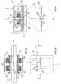
- Figure 1 shows a test object 1, for example a blank, having on its surface a defect 8, for example a crack.
- a surface transducer coil 2 is placed inside a transducer casing 6,7.
- a part-device 4 is fitted as protection between the coil 2 and the surface of the test object 1.
- This part-device consists wholly or partially of electrically conducting material, for example stainless steel, and has the shape of a plate. If this plate were entirely homogeneous it would constitute an effective obstacle to the magnetic field which is supposed to penetrate the plate on its way from the coil to the test object and vice-versa. Thus optimal detection of the crack 8 would be prevented.
- the plate will constitute a short-circuited turn around the ferrite pole 3 conducting the magnetic flux. This causes, like a short-circuited turn on a transformer leg, a strong current flowing around the pin in the steel plate thereby strongly reinforcing the dampening effect of the eddy currents.
- Figure 2 shows the plate 4 seen from above. It consists of non-magnetic stainless steel such as SIS 2333 and is 1 mm thick, for instance. It has the same mechanical strength and resistance to the environment as steel. An effective obstacle to the circular current paths 11 is obtained by providing a groove or slit 10 in the plate. The plate or part-device then no longer constitutes a short-circuited turn, and the arrangement of the groove 10 causes considerable reduction of the dampening currents in the plate 4. The magnetic flux can thus pass via the ferrite pole through the channel 9 in the plate 4, without being dampened to any great extent.
- the groove 10 in Figure 2 has a width SB which may be only a fraction of a millimeter.
- the width is not critical and is chosen so that it can be filled with a suitable electrically insulating material 5.
- This material 5 may also be used to cover the plate 4 entirely if advisable.
- the part-device 4 for example the plate in Figures 1 and 2, from forming an integral part of the surrounding walls or casing 6.
- the casing 6 is made of electrically conducting material, for example metal
- the groove 10 in the plate will be bridged at its radially outer edge enabling the current 11 in the plate to flow around the groove 10 thus causing a certain amount of dampening.
- the current would be greatest nearest the ferrite pole 3 if there were no groove or if there were a bridging of the groove, but dampening will also be manifest with a groove and its remote outer bridging.
- the plate 4 may be galvanically separated from the casing by means of an insulating layer 18, for instance, between the plate 4 and the casing 6. It is of course also important to protect the groove 10 so that no electrically conducting bridging occurs due to metal flakes or the like. Silicon film, for instance, provides suitable protection and can easily be applied on the plate. The higher the frequency, the better will be the effect of the groove.
- the ratio for the flux 14 between pole and test object with and without the groove 10, respectively is about 5.
- the groove increases the flux by a factor of 5 and this improves the measuring potential by a corresponding factor.
- carrier frequencies of the alternating current setting up the magnetic field are used to an increasing extent in modern eddy current technology.
- the magnetic fields of these different frequencies are dampened to a frequency-dependent varying degree by a homogeneous plate (without a groove). But if the plate is provided with a groove or the like which prevents or renders more difficult the formation of current paths, the magnetic fields of the various frequencies will be dampened to a much less varying extent. This means that the present invention facilitates the use of so-called multi-frequency principles.
- the invention can here open the door to rolled wire testing using more than one frequency.
- Figure 1 also shows how coolant, for example water (H2O), is allowed to pass between the coil 2 and plate 4.
- the plate also acts as a guide for the water flow.
- the protective device/plate may thus fulfill several functions and the number of grooves or other arrangements impeding the formation of eddy currents paths in the plate may be varied in many ways.
- the plate may of course consist of several parts.
- the plate may be manufactured of stainless steel which has relatively poor electrical conductivity, but even ordinary steel may be used since its magnetic permeability increases the skin effect and thus renders more difficult the flow of eddy currents.
- the plate may also be laminated but the simplicity of the device is then lost to a certain extent, as is also its heat-resistance.
- Figure 3 shows an example of how the ferrite pole 3 can be supplemented by additional ferrite poles 12, so that the flux is directed, bundled and strengthened as well as being able to pass easily through the plate 4.
- the sensitive coil 2 can be distanced from the test object and located in a more protected position, while the plate 4 also acts as a robust and strong mechanical protection.
- the coil 2 is suitably wound of copper foil, for example 3 mm wide and 0.1 mm thick, and provided with plastic film as insulation between the layers. The effective copper area will then be large while the skin effect will less affect the copper of the coil.
- Figures 1 to 4 show surface transducers.
- Figures 5A and 5B show how the present invention may be used, for example, in so called through-transducers 2, 22.
- the test object 1 is in this case a circular rod moving at a speed V V through the differential-connected coils 2 and 22. These coils are partially surrounded by the ferrite yoke 3 which protrudes into cavities/channels in the tube-shaped protective part-device 4.
- the coils 2, 22 are fixed to the stand/casing 7 via attachment means 16. However, the bearings 15 allows the ferrite yoke 3 and tube 4 to rotate.
- the circular speed of rotation of the tube is V R .
- a long axial surface crack 8 will be passed by respective ferrite yokes and their field picture once per revolution as long as the crack remains within the coils. If, thus, the ferrite poles are somewhat displaced, as indicated by S, in relation to each other, the flux passage across the crack will occur with a slight time displacement in relation to each coil 2 and 22. Due to the differential coil connection, therefore, a signal will be generated which can be utilized to detect the crack 8.
- Figure 5 may also be looked upon as an example of how a conventional differential transducer, comprising the two opposing through-coils 2 and 22, can be supplemented by rotating ferrite yokes 3.
- This enables the differential coil arrangement to detect "long defects” such as long axial cracks or the like, as well as “short defects". This could not be done efficiently without the slits 10, especially not at higher carrier frequencies. Shallower cracks require higher frequencies and consequently a more accentuated skin effect.
- the coil arrangement in Figure 5 can also function as a conventional differential transducer for short defects, but be supplemented by the present invention so that long defects can also be detected via the differential coil arrangement.
- U-shaped ferrite yokes for instance, can be varied depending on the quantity to be detected.
- SE-B-8503894-1 describes a method of rotating an eddy-current transducer rapidly by means of a "top". If a ceramic plate is used as protection here, the cooling water will explode the plate due to the great centrifugal force occurring as a result of the high revolution rate, often several thousand rpm. If a steel plate according to the invention, for instance, is used instead of the ceramic plate the risk of explosion is eliminated.
- FIG. 6 shows another embodiment with a surface transducer 2 including a ferrite yoke, fitted in a casing 6.
- the protective plate 4 is glued to a ceramic plate 40 which is not electrically conducting.
- the plate 4 consists of two parts which are thus held together by the ceramic plate 40.
- the ceramic plate seals the groove 10 and protects the lower end of the ferrite pole 3.
- a recess is provided in the ceramic plate 40, permitting water flowing via the hollow 19 in the ferrite pole 3 to pass and cool the ferrite pole 3 and coil 2.
- the ceramic plate 40 in combination with the stainless plate 4 provides excellent protection in several respects, both mechanically and electrically.
- a device for example a measuring head, based on the use of eddy current technology, comprising a part-device 4 of electrically conducting material, for example steel, including a channel, for example a hole or the like, this channel in turn containing material with good magnetic-flux conducting properties, for example ferrite (u rel >1).
- a part of the part-device, subjected to or surrounding the magnetic flux, is provided with arrangements, for example grooves/slits 10 which impede or completely prevent the formation of dampening currents in the part-device connected to the transducer/sensor 2.
Landscapes
- Chemical & Material Sciences (AREA)
- Chemical Kinetics & Catalysis (AREA)
- Electrochemistry (AREA)
- Physics & Mathematics (AREA)
- Health & Medical Sciences (AREA)
- Life Sciences & Earth Sciences (AREA)
- Analytical Chemistry (AREA)
- Biochemistry (AREA)
- General Health & Medical Sciences (AREA)
- General Physics & Mathematics (AREA)
- Immunology (AREA)
- Pathology (AREA)
- Investigating Or Analyzing Materials By The Use Of Magnetic Means (AREA)
Applications Claiming Priority (1)
| Application Number | Priority Date | Filing Date | Title |
|---|---|---|---|
| SE9002492A SE467176B (sv) | 1990-07-24 | 1990-07-24 | Anordning foer att reducera daempning vid/av virvelstroemsgivare |
Publications (1)
| Publication Number | Publication Date |
|---|---|
| EP0524342A1 true EP0524342A1 (fr) | 1993-01-27 |
Family
ID=20380040
Family Applications (1)
| Application Number | Title | Priority Date | Filing Date |
|---|---|---|---|
| EP91112571A Withdrawn EP0524342A1 (fr) | 1990-07-24 | 1991-07-25 | Transducteur basé à la technologie de courant de Foucault |
Country Status (4)
| Country | Link |
|---|---|
| EP (1) | EP0524342A1 (fr) |
| JP (1) | JPH04282452A (fr) |
| CA (1) | CA2047661A1 (fr) |
| SE (1) | SE467176B (fr) |
Cited By (1)
| Publication number | Priority date | Publication date | Assignee | Title |
|---|---|---|---|---|
| US12436131B2 (en) * | 2021-04-22 | 2025-10-07 | Evident Canada, Inc. | High temperature ECA probe |
Citations (4)
| Publication number | Priority date | Publication date | Assignee | Title |
|---|---|---|---|---|
| EP0027525A1 (fr) * | 1979-09-18 | 1981-04-29 | Institut Dr. Friedrich Förster Prüfgerätebau GmbH & Co. KG | Sonde de contrôle pour l'exploration de la surface d'une pièce métallique d'essai |
| EP0152904A2 (fr) * | 1984-02-17 | 1985-08-28 | Törnbloms Kvalitetskontroll Ab | Méthode et dispositif pour le test, et/ou la mesure d'objets électriquement conducteurs devant être testés |
| WO1986000412A1 (fr) * | 1984-06-27 | 1986-01-16 | Ltv Steel Company, Inc. | Detecteur de defauts a courants parasites possedant un manchon rotatif definissant un champ magnetique |
| WO2015002904A2 (fr) * | 2013-06-30 | 2015-01-08 | Fereidoun Abbassian | Système et console permettant de surveiller et de gérer des opérations sur un emplacement de puits |
-
1990
- 1990-07-24 SE SE9002492A patent/SE467176B/sv not_active IP Right Cessation
-
1991
- 1991-07-23 JP JP3182335A patent/JPH04282452A/ja active Pending
- 1991-07-23 CA CA002047661A patent/CA2047661A1/fr not_active Abandoned
- 1991-07-25 EP EP91112571A patent/EP0524342A1/fr not_active Withdrawn
Patent Citations (4)
| Publication number | Priority date | Publication date | Assignee | Title |
|---|---|---|---|---|
| EP0027525A1 (fr) * | 1979-09-18 | 1981-04-29 | Institut Dr. Friedrich Förster Prüfgerätebau GmbH & Co. KG | Sonde de contrôle pour l'exploration de la surface d'une pièce métallique d'essai |
| EP0152904A2 (fr) * | 1984-02-17 | 1985-08-28 | Törnbloms Kvalitetskontroll Ab | Méthode et dispositif pour le test, et/ou la mesure d'objets électriquement conducteurs devant être testés |
| WO1986000412A1 (fr) * | 1984-06-27 | 1986-01-16 | Ltv Steel Company, Inc. | Detecteur de defauts a courants parasites possedant un manchon rotatif definissant un champ magnetique |
| WO2015002904A2 (fr) * | 2013-06-30 | 2015-01-08 | Fereidoun Abbassian | Système et console permettant de surveiller et de gérer des opérations sur un emplacement de puits |
Non-Patent Citations (1)
| Title |
|---|
| PATENT ABSTRACTS OF JAPAN, vol. 8, no. 121 (P-278)[1558], 7th June 1984; & JP-A-59 26 054 (MITSUBISHI) 10-02-1984 * |
Cited By (1)
| Publication number | Priority date | Publication date | Assignee | Title |
|---|---|---|---|---|
| US12436131B2 (en) * | 2021-04-22 | 2025-10-07 | Evident Canada, Inc. | High temperature ECA probe |
Also Published As
| Publication number | Publication date |
|---|---|
| CA2047661A1 (fr) | 1992-01-25 |
| JPH04282452A (ja) | 1992-10-07 |
| SE467176B (sv) | 1992-06-01 |
| SE9002492L (sv) | 1992-01-25 |
| SE9002492D0 (sv) | 1990-07-24 |
Similar Documents
| Publication | Publication Date | Title |
|---|---|---|
| US5689070A (en) | High temperature electromagnetic acoustic transducer (EMAT) probe and coil assemblies | |
| US7023205B1 (en) | Eddy current sensor capable of sensing through a conductive barrier | |
| US20030080728A1 (en) | Motion measuring device | |
| JPS6330223Y2 (fr) | ||
| Guo et al. | A model of magnetic field and braking torque in liquid-cooled permanent-magnet retarder accounting for the skin effect on permeability | |
| KR900010371A (ko) | 왜곡 검출장치 | |
| Gyftakis et al. | Detection of simultaneous mechanical faults in 6‐kV pumping induction motors using combined MCSA and stray flux methods | |
| KR20080064964A (ko) | 동기 장치 | |
| US6489781B1 (en) | Method and system for detecting core faults | |
| CA2214773A1 (fr) | Detecteur de courants de foucault et outil d'essai de tube comprenant au moins un detecteur | |
| EP0524342A1 (fr) | Transducteur basé à la technologie de courant de Foucault | |
| US3428838A (en) | Wear detector for fluid-cooled electric machine | |
| CA2593553C (fr) | Sonde de deplacement pour moteur d'avion | |
| US5187435A (en) | Non-destructive test apparatus with eddy current transducer rotary head and field homogenizing conductive ring for scanning metal test materials | |
| Ferraris et al. | A novel thermographic method and its improvement to evaluate defects in laminated and Soft Magnetic Composites devices | |
| Tu et al. | Electromagnetic diagnostic system for the Keda Torus eXperiment | |
| KR100442642B1 (ko) | 선재 표면흠 검사용 와전류 센서 | |
| Särkimäki | Radio frequency measurement method for detecting bearing currents in induction motors | |
| EP0388821A2 (fr) | Méthode pour contrôler et/ou mesurer à l'aide d'un générateur de flux | |
| Tavner et al. | Influence of winding design on the axial flux in laminated-stator cores | |
| US20070052413A1 (en) | Device for testing a test specimen for surface faults by magnetization means and by means of induction process as measurement sensors | |
| US1974422A (en) | Vibration detector | |
| EP3517977B1 (fr) | Capteur magnétique de turbine à gaz | |
| US3506912A (en) | Large generator shaft voltage reducing arrangement and indicator | |
| SE445616B (sv) | Forfarande att introducera elektromagnetiskt ultraljud i elektriskt ledande material vid oforstorande provning samt anordning for utforande av forfarandet |
Legal Events
| Date | Code | Title | Description |
|---|---|---|---|
| PUAI | Public reference made under article 153(3) epc to a published international application that has entered the european phase |
Free format text: ORIGINAL CODE: 0009012 |
|
| AK | Designated contracting states |
Kind code of ref document: A1 Designated state(s): AT DE FR GB IT |
|
| 17P | Request for examination filed |
Effective date: 19930612 |
|
| STAA | Information on the status of an ep patent application or granted ep patent |
Free format text: STATUS: THE APPLICATION IS DEEMED TO BE WITHDRAWN |
|
| 18D | Application deemed to be withdrawn |
Effective date: 19950201 |