EP0524483A2 - Machine d'étiquetage - Google Patents
Machine d'étiquetage Download PDFInfo
- Publication number
- EP0524483A2 EP0524483A2 EP92111517A EP92111517A EP0524483A2 EP 0524483 A2 EP0524483 A2 EP 0524483A2 EP 92111517 A EP92111517 A EP 92111517A EP 92111517 A EP92111517 A EP 92111517A EP 0524483 A2 EP0524483 A2 EP 0524483A2
- Authority
- EP
- European Patent Office
- Prior art keywords
- container
- wall
- labeling machine
- stripper
- machine according
- Prior art date
- Legal status (The legal status is an assumption and is not a legal conclusion. Google has not performed a legal analysis and makes no representation as to the accuracy of the status listed.)
- Granted
Links
- 238000002372 labelling Methods 0.000 title claims abstract description 33
- 239000000853 adhesive Substances 0.000 claims description 9
- 238000000034 method Methods 0.000 claims description 6
- 238000007664 blowing Methods 0.000 description 16
- 238000009833 condensation Methods 0.000 description 8
- 230000005494 condensation Effects 0.000 description 8
- 238000001035 drying Methods 0.000 description 8
- 239000003292 glue Substances 0.000 description 4
- 230000032258 transport Effects 0.000 description 4
- XLYOFNOQVPJJNP-UHFFFAOYSA-N water Substances O XLYOFNOQVPJJNP-UHFFFAOYSA-N 0.000 description 4
- 239000007788 liquid Substances 0.000 description 3
- 230000004888 barrier function Effects 0.000 description 2
- 239000011248 coating agent Substances 0.000 description 1
- 238000000576 coating method Methods 0.000 description 1
- 238000011049 filling Methods 0.000 description 1
- 238000005429 filling process Methods 0.000 description 1
- 238000004806 packaging method and process Methods 0.000 description 1
- 230000000246 remedial effect Effects 0.000 description 1
- 238000000926 separation method Methods 0.000 description 1
Images


Classifications
-
- B—PERFORMING OPERATIONS; TRANSPORTING
- B65—CONVEYING; PACKING; STORING; HANDLING THIN OR FILAMENTARY MATERIAL
- B65C—LABELLING OR TAGGING MACHINES, APPARATUS, OR PROCESSES
- B65C9/00—Details of labelling machines or apparatus
- B65C9/0015—Preparing the labels or articles, e.g. smoothing, removing air bubbles
Definitions
- the invention relates to a labeling machine for containers, in particular bottles, by means of which each container is provided with at least one label, in particular a self-adhesive label, and with a device for removing any moisture present on the outer wall of the container before labeling.
- a large number of devices are known for applying self-adhesive labels to containers, in particular bottles. It is always of particular importance that the applied labels adhere perfectly and in particular are also glued over the entire surface.
- the problem often arises that the self-adhesive labels to be applied to the outside of the bottle after the filling process do not adhere properly, which not only looks unattractive and reduces the incentive to buy, but also — if the label falls off — also means that the bottle contents no longer can be identified.
- the invention is therefore based on the object of providing a labeling machine of the type mentioned at the outset which ensures that the labels are held securely and reliably on containers, in particular bottles, preferably filled.
- the device is designed as a moisture wiping device, the wiper of which strikes the outer wall of the container and that a relative movement between the container and the wiper is carried out for the wiping process.
- the moisture wiping device By means of the moisture wiping device according to the invention, documents such as condensation or condensation water can be removed from the outer wall of the container so that subsequently applied self-adhesive labels find a perfect base for a secure hold. Condensation and condensation water occur in particular when a liquid (eg a drink) is poured into the container.
- the invention is characterized by a particularly simple design and reliably ensures that moisture is removed to a sufficient extent before the labeling process.
- the moisture is removed by means of a wiping process, that is to say a wiper strikes the outer wall of the container and there is a relative movement between the outer wall of the container and the wiper, whereby the moisture is "pushed aside". This will drain the outer wall of the container.
- the self-adhesive label is then applied to this dry or almost dry surface. If wet glue labels are used, the invention ensures that the outer wall of the container is first drained before wet glue or the wet glue label is applied. This prevents over-humidification.
- a container rotating device which rotates the container about its vertical axis at least when the scraper is in contact with the outer wall of the container.
- the container therefore performs a relative movement to the fixed scraper.
- the scraper glides along the outer wall of the container during the rotation of the container and thereby removes the coating there, especially the moisture.
- the scraper In principle, however, it is also possible for the scraper to be guided peripherally along the outer wall of the container while the container is stationary.
- the scraper can be moved approximately in the radial direction of the container for bearing against the outer wall of the container.
- the scraper is between two guide rollers or in the region of two guide rollers which, together with the scraper, are moved towards the container and thereby press the container against a drive roller.
- the drive roller gives the container a rotational movement about its vertical axis.
- the guide rollers and / or the drive roller has a resilient, elastic covering, which on the one hand provides a safe bottle rotation due to a sufficient frictional moment and on the other hand the scraper comes into safe contact with the outer wall of the container.
- at least one of the guide rollers is provided with a drive and that the roller previously provided as the drive roller only acts as a counter pressure roller.
- the wiper is designed in the manner of a wiper blade of a windshield wiper.
- the longitudinal direction of the wiper extends approximately parallel or slightly inclined to the vertical axis of the container.
- the contour / setting of the wiper blade is adapted to the shape of the outer periphery of the container, so that the wiper blade is always in contact with the outer wall of the container over its entire length.
- the above-mentioned inclination of the wiper blade with respect to the vertical axis of the container is preferably selected such that - viewed in the direction of rotation of the container - a higher point (considered) of a certain angular coordinate of the container earlier on the scraper during the rotational movement hits as a lower lying point of the same angular coordinate.
- This inclination of the wiper blade supports the removal of the liquid stripped from the surface of the container.
- blowing air nozzle directed towards the outer wall of the container.
- a plurality of blowing air nozzles are preferably provided in order to be able to carry out a large-area drying in accordance with the longitudinal extent of the wiper blade. This large number of blowing nozzles saves blowing air compared to a single strong blowing blowing nozzle.
- the blowing air is clocked, which also reduces the blowing air consumption. "Clocked" means that there is only blowing while a container is in the device.
- the labeling device 1 (labeling machine), of which only a region is shown in FIG. 1, has a container transport device 2 with a link chain belt 3, which is constructed in the manner of a conveyor belt. It has an upper run and a lower run, the upper run serving as a standing surface for containers 6 which are designed as bottles 7. The upper run therefore transports the bottles 7 in the direction of the arrow 9.
- the transport width of the container transport device 2 can be adjusted to the diameter of the bottles 7 by means of adjusting devices 10.
- a separating device 13 In the inlet area 12 of the labeling device 1, a separating device 13 is provided which projects into the area of the link chain belt 3 with a swivel lever 15.
- the swivel lever 15 has at its free end a retaining lug against which the foremost bottle 7 of a queue bears in the locked state of the separating device 13. Since the link chain belt 3 rotates continuously during operation of the labeling device 1, it slips over the standing surfaces of the bottles 7, provided that the separation device 13 does not release them.
- a piston / cylinder unit 17, which actuates the pivoting lever 15, is provided for releasing the separating device 13.
- the separating device 13 is followed by a device 18 for removing moisture or the like which may be present on the outer wall of the container / outer wall of the bottle.
- a device 18 for removing moisture or the like which may be present on the outer wall of the container / outer wall of the bottle. The structure and mode of operation of this device 18 will be discussed in more detail below.
- the device 18 is followed by a labeling station 19 which pastes the bottles 7 with self-adhesive labels.
- the labeling station 19 has a drive rubber roller 22 which projects with part of its outer surface into the area of the link chain belt 3.
- two counter pressure rollers 24 are provided, which are mounted on fork arms of a fork 26.
- the fork 26 can be moved in the direction of the double arrow 27 towards the drive rubber roller 22 in such a way that a container 6 is caught between the drive rubber roller 22 and the counterpressure rollers 24 and, due to the drive rubber roller 22, is rotated about its vertical axis.
- the movement control of the fork 26 is preferably carried out with a sensor, in particular with a light barrier.
- the self-adhesive labels are arranged on a label tape carrier 31. They are detached from this label tape carrier 31 by means of a dispensing device 32 and then transferred to the bottle in each case.
- a dispensing device 32 For this purpose, the bottle 7 captured by the drive rubber roller 22 and the counter-pressure rollers 24 is rotated and the label tape carrier 31 is moved further and thereby a dispensing edge 36 is guided around, whereby the foremost label is pushed off and fed tangentially to the outer wall of the bottle and glued there.
- the fork 26 moves back into the starting position and thereby releases the labeled bottle 7, which is then transported by means of the link chain belt 3 to a further labeling station (for example for applying a neck label) or to a packaging station.
- the device 18 for removing moisture or the like present on the outer wall of the bottle will now be discussed in more detail.
- the device 18 has a drive roller 38 which projects with part of its outer surface into the area of the link chain belt 3.
- the outer surface of the drive roller 37 is provided with a resilient covering, for example rubber or the like.
- two guide rollers 39 are provided which are rotatably mounted on fork arms 40 of a fork 41 which are spaced apart from one another in parallel.
- the fork 41 can be moved towards and away from the drive roller 38 along the double arrow 42.
- the device 18 has a moisture wiping device 43 and a drying device 44 for removing residual moisture on.
- the drying device 44 is connected to a compressed air line 45 for supplying blown air.
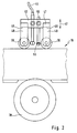
- FIGS. 2 and 3 show the device 18 in detail.
- Each guide roller 39 is held by two fork arms 40, the rear end region 46 of which is fastened to a U-shaped frame 47.
- An actuating rod 49 is fastened to the crosspiece 48 of the frame 47, with which the fork 41 can be moved in the direction of the double arrow 42.
- the two legs 51 of the U-shaped frame 47 are connected via a web 52, which is located approximately in the central section of the guide rollers 39.
- the moisture wiping device 43 and the drying device 44 are fastened to the web 52.
- the moisture wiper device 43 has a wiper 53 which is designed as a wiper blade 54 in the manner of a windshield wiper.
- the wiper blade 54 is held by a back web 55.
- the back web 55 is fastened at a right angle to a holding rod 56 in the middle.
- the holding rod passes through a through bore 57 in the web 52.
- a threaded bore 59 extends from the top 58 of the web 52 and meets the through bore 57.
- a locking screw 60 is screwed into the threaded bore 59. With the locking screw 60 loosened, the wiper blade 54 can be adjusted to the correct distance and inclined with respect to the vertical axis of the bottles 7.
- the distance is adjusted such that when the bottle 7 is trapped between the guide rollers 39 and the drive roller 38, the front wiping edge of the wiper blade 54 comes into contact with the bottle.
- the wiper blade 54 is preferably made of rubber or the like.
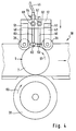
- the above-mentioned inclination is preferably chosen such that, viewed in the direction of rotation of the container (arrow 61 in FIG. 4), a higher point of a certain angular coordinate of the bottle 7 occurs earlier on the scraper 53 during the rotational movement than a lower point of the same angular coordinate.
- the drying device 44 consists of a tube 62, a cross tube 63 and a compressed air connection 64 to which the already mentioned compressed air line 45 is connected.
- the tube 62 is closed at both ends and has openings / blowing nozzles 65 which are spaced apart from one another on its lateral surface facing a captured bottle 7.
- the transverse tube 63 which is fastened vertically and approximately centrally to the tube 62, passes through a through bore 66 of the web 52.
- a threaded bore 67 opens into the through bore 66, into which a locking screw 68 is screwed, from the top 58 of the web 52.
- the locking screw 68 is loosened, the drying device 44 is adjusted in such a way that the blowing nozzles 65 lie at a short distance from a captured bottle 7, the Tube 62 preferably runs parallel to wiper blade 54.
- the device 18 operates as follows: If a bottle 7 is released by the separating device 13, the fork 41 moves - controlled by a sensor or a light barrier - in the direction of the drive roller 38 such that the bottle 7 is clamped between the guide rollers 39 and the drive roller 38. By rotating the drive roller 38 in the direction of arrow 69, the bottle 7 rotates about its vertical axis in the direction of arrow 61, as shown in FIG. 4-. In this position, the wiper blade 54 comes against the outside of the bottle and brushes moisture present there (condensation and condensation water). and the like. At the same time, the outer wall of the bottle is blown with blowing air by means of the blowing nozzles 65 in order to dry off any residual moisture.
- the drying device 44 is - seen in the direction of rotation of the bottle 7 - downstream of the moisture wiping device 43. If the outer wall of the container or a desired area of the outer wall of the container to which the self-adhesive label is later applied is dry, the fork 41 moves back into the starting position, whereby the bottle 7 is released and fed to the labeling station 19 by means of the link chain belt 3. The labeling then takes place there.
- the wiping time of the stripper 50 and / or the blowing time the drying device 44 adjustable. Suitable control devices are provided for this.
- the wiping time and / or the blowing time are set as a function of the container speed and the container diameter. Furthermore, it is not absolutely necessary for the entire circumference of the container to be wiped and / or blown, since it may be sufficient to treat only the circumferential section which receives the label.
Landscapes
- Labeling Devices (AREA)
- Cleaning In General (AREA)
- Apparatuses For Bulk Treatment Of Fruits And Vegetables And Apparatuses For Preparing Feeds (AREA)
- Soil Working Implements (AREA)
Applications Claiming Priority (2)
| Application Number | Priority Date | Filing Date | Title |
|---|---|---|---|
| DE4124242 | 1991-07-22 | ||
| DE4124242A DE4124242A1 (de) | 1991-07-22 | 1991-07-22 | Etikettiermaschine |
Publications (3)
| Publication Number | Publication Date |
|---|---|
| EP0524483A2 true EP0524483A2 (fr) | 1993-01-27 |
| EP0524483A3 EP0524483A3 (en) | 1993-05-26 |
| EP0524483B1 EP0524483B1 (fr) | 1995-10-11 |
Family
ID=6436728
Family Applications (1)
| Application Number | Title | Priority Date | Filing Date |
|---|---|---|---|
| EP92111517A Expired - Lifetime EP0524483B1 (fr) | 1991-07-22 | 1992-07-07 | Machine d'étiquetage |
Country Status (4)
| Country | Link |
|---|---|
| EP (1) | EP0524483B1 (fr) |
| AT (1) | ATE128928T1 (fr) |
| DE (1) | DE4124242A1 (fr) |
| HU (1) | HUT66479A (fr) |
Cited By (1)
| Publication number | Priority date | Publication date | Assignee | Title |
|---|---|---|---|---|
| EP2319770A1 (fr) * | 2009-11-09 | 2011-05-11 | Krones AG | Dispositif et procédé destinés à l'étiquetage de récipients remplis |
Families Citing this family (1)
| Publication number | Priority date | Publication date | Assignee | Title |
|---|---|---|---|---|
| DE4419578B4 (de) * | 1994-06-03 | 2006-08-31 | Khs Eti-Tec Maschinenbau Gmbh | Etikettierstation |
Family Cites Families (5)
| Publication number | Priority date | Publication date | Assignee | Title |
|---|---|---|---|---|
| US2683315A (en) * | 1950-03-03 | 1954-07-13 | Gerber Prod | Method of drying wet containers |
| DE913747C (de) * | 1952-01-23 | 1954-06-18 | Jagenberg Werke Ag | Maschinenanlage zum Fuellen und Etikettieren von Flaschen |
| DE3217526C2 (de) * | 1982-05-10 | 1985-08-14 | Langguth GmbH & Co, 4400 Münster | Trocknungsvorrichtung für zu etikettierende Behälter |
| US4683009A (en) * | 1985-04-01 | 1987-07-28 | Adolph Coors Company | Bottle drying apparatus |
| GB8911336D0 (en) * | 1989-05-17 | 1989-07-05 | Heinz Co H J | Removing surface liquid from articles |
-
1991
- 1991-07-22 DE DE4124242A patent/DE4124242A1/de not_active Withdrawn
-
1992
- 1992-07-07 AT AT92111517T patent/ATE128928T1/de not_active IP Right Cessation
- 1992-07-07 EP EP92111517A patent/EP0524483B1/fr not_active Expired - Lifetime
- 1992-07-21 HU HU9202381A patent/HUT66479A/hu unknown
Cited By (2)
| Publication number | Priority date | Publication date | Assignee | Title |
|---|---|---|---|---|
| EP2319770A1 (fr) * | 2009-11-09 | 2011-05-11 | Krones AG | Dispositif et procédé destinés à l'étiquetage de récipients remplis |
| EP2361835A1 (fr) * | 2009-11-09 | 2011-08-31 | Krones AG | Dispositif et procédé destinés à l'étiquetage de récipients remplis |
Also Published As
| Publication number | Publication date |
|---|---|
| HUT66479A (en) | 1994-11-28 |
| EP0524483A3 (en) | 1993-05-26 |
| EP0524483B1 (fr) | 1995-10-11 |
| ATE128928T1 (de) | 1995-10-15 |
| DE4124242A1 (de) | 1993-01-28 |
Similar Documents
| Publication | Publication Date | Title |
|---|---|---|
| DE4219051C2 (de) | Vorrichtung zum Entfernen von Etiketten von Behältern | |
| DE9016591U1 (de) | Vorrichtung zum Ausstatten von Gefäßen mit Etiketten | |
| DE1923587C3 (de) | Vorrichtung zum axialen Abziehen von über dornartige Träger einer schrittweise bewegten Zuführungsvorrichtung gestülpten Behälterteilen | |
| DE2936989A1 (de) | Verfahren und vorrichtung zum oeffnen eines zylindrischen folienschlauches sowie zu dessen ueberstuelpen ueber einen gegenstand | |
| EP0364837B1 (fr) | Dispositif d'étiquetage pour opposer une étiquette sur un support, en particulier une étiquette de grand format sur un rouleau de papier ainsi que méthode d'application | |
| DE3152881C2 (de) | Verfahren und Vorrichtung zur Codierung von Gegenständen | |
| EP0524483B1 (fr) | Machine d'étiquetage | |
| EP0441365B1 (fr) | Procédé et dispositif pour appliquer des étiquettes sur des récipients ou supports similaires | |
| EP0584542B1 (fr) | Méthode et dispositif pour imprimer des objets | |
| DE69709777T2 (de) | Umfangsgetriebener etikettierer | |
| EP2322293B1 (fr) | Dispositif et procédé d'enlèvement d'étiquettes d'objets | |
| DE19821253A1 (de) | Beleimungsstation für eine Etikettiermaschine sowie Etikettiermaschine | |
| EP0123097A1 (fr) | Procédé pour l'étiquetage semi-automatique ou automatique d'articles ainsi que le dispositif d'étiquetage pour la réalisation de ce procédé | |
| EP0566918B1 (fr) | Dispositif d'étiquetage de récipients | |
| DE3504303A1 (de) | Vorrichtung zum entfernen von etiketten | |
| DE68903813T2 (de) | Verfahren und vorrichtung zum auftragen von klebstoff zur dichten montage von deckeln auf verpackungen und containern. | |
| DE19701892C2 (de) | Verfahren und Vorrichtung zum Entetikettieren von Getränkebehältern | |
| DE8504768U1 (de) | Vorrichtung zum trockenen Ablösen von Etiketten von Behältnissen | |
| EP0369348B1 (fr) | Dispositif pour appliquer une bande adhésif | |
| DE20109063U1 (de) | Vorrichtung zum Abziehen von Haftetiketten | |
| DE3628425A1 (de) | Etikettiergeraet | |
| DE9218941U1 (de) | Schnellaufetikettiervorrichtung | |
| AT391457B (de) | Vorrichtung zum anbringen von aufklebern ueber den verschluss von flaschen | |
| DE8504435U1 (de) | Vorrichtung zum entfernen von netzfluessigkeit von flaschen in etikettiermaschinen | |
| DE2740575B2 (de) | Etikettierstation |
Legal Events
| Date | Code | Title | Description |
|---|---|---|---|
| PUAI | Public reference made under article 153(3) epc to a published international application that has entered the european phase |
Free format text: ORIGINAL CODE: 0009012 |
|
| AK | Designated contracting states |
Kind code of ref document: A2 Designated state(s): AT CH ES FR GB GR IT LI PT |
|
| PUAL | Search report despatched |
Free format text: ORIGINAL CODE: 0009013 |
|
| AK | Designated contracting states |
Kind code of ref document: A3 Designated state(s): AT CH ES FR GB GR IT LI PT |
|
| 17P | Request for examination filed |
Effective date: 19931111 |
|
| 17Q | First examination report despatched |
Effective date: 19940624 |
|
| GRAA | (expected) grant |
Free format text: ORIGINAL CODE: 0009210 |
|
| AK | Designated contracting states |
Kind code of ref document: B1 Designated state(s): AT CH ES FR GB GR IT LI PT |
|
| PG25 | Lapsed in a contracting state [announced via postgrant information from national office to epo] |
Ref country code: FR Effective date: 19951011 Ref country code: GB Effective date: 19951011 Ref country code: GR Free format text: LAPSE BECAUSE OF FAILURE TO SUBMIT A TRANSLATION OF THE DESCRIPTION OR TO PAY THE FEE WITHIN THE PRESCRIBED TIME-LIMIT Effective date: 19951011 Ref country code: ES Free format text: THE PATENT HAS BEEN ANNULLED BY A DECISION OF A NATIONAL AUTHORITY Effective date: 19951011 Ref country code: IT Free format text: LAPSE BECAUSE OF FAILURE TO SUBMIT A TRANSLATION OF THE DESCRIPTION OR TO PAY THE FEE WITHIN THE PRE;WARNING: LAPSES OF ITALIAN PATENTS WITH EFFECTIVE DATE BEFORE 2007 MAY HAVE OCCURRED AT ANY TIME BEFORE 2007. THE CORRECT EFFECTIVE DATE MAY BE DIFFERENT FROM THE ONE RECORDED.SCRIBED TIME-LIMIT Effective date: 19951011 |
|
| REF | Corresponds to: |
Ref document number: 128928 Country of ref document: AT Date of ref document: 19951015 Kind code of ref document: T |
|
| PG25 | Lapsed in a contracting state [announced via postgrant information from national office to epo] |
Ref country code: PT Effective date: 19960111 |
|
| EN | Fr: translation not filed | ||
| GBV | Gb: ep patent (uk) treated as always having been void in accordance with gb section 77(7)/1977 [no translation filed] |
Effective date: 19951011 |
|
| PG25 | Lapsed in a contracting state [announced via postgrant information from national office to epo] |
Ref country code: AT Effective date: 19960707 |
|
| PG25 | Lapsed in a contracting state [announced via postgrant information from national office to epo] |
Ref country code: LI Effective date: 19960731 Ref country code: CH Effective date: 19960731 |
|
| PLBE | No opposition filed within time limit |
Free format text: ORIGINAL CODE: 0009261 |
|
| STAA | Information on the status of an ep patent application or granted ep patent |
Free format text: STATUS: NO OPPOSITION FILED WITHIN TIME LIMIT |
|
| 26N | No opposition filed | ||
| REG | Reference to a national code |
Ref country code: CH Ref legal event code: PL |