EP0524769A2 - Vorrichtung für ein Fluidabtrennungsverfahren - Google Patents
Vorrichtung für ein Fluidabtrennungsverfahren Download PDFInfo
- Publication number
- EP0524769A2 EP0524769A2 EP92306510A EP92306510A EP0524769A2 EP 0524769 A2 EP0524769 A2 EP 0524769A2 EP 92306510 A EP92306510 A EP 92306510A EP 92306510 A EP92306510 A EP 92306510A EP 0524769 A2 EP0524769 A2 EP 0524769A2
- Authority
- EP
- European Patent Office
- Prior art keywords
- membrane
- vessel
- fluid
- over
- tubular
- Prior art date
- Legal status (The legal status is an assumption and is not a legal conclusion. Google has not performed a legal analysis and makes no representation as to the accuracy of the status listed.)
- Withdrawn
Links
Images

Classifications
-
- B—PERFORMING OPERATIONS; TRANSPORTING
- B01—PHYSICAL OR CHEMICAL PROCESSES OR APPARATUS IN GENERAL
- B01D—SEPARATION
- B01D65/00—Accessories or auxiliary operations, in general, for separation processes or apparatus using semi-permeable membranes
- B01D65/08—Prevention of membrane fouling or of concentration polarisation
-
- B—PERFORMING OPERATIONS; TRANSPORTING
- B01—PHYSICAL OR CHEMICAL PROCESSES OR APPARATUS IN GENERAL
- B01D—SEPARATION
- B01D53/00—Separation of gases or vapours; Recovering vapours of volatile solvents from gases; Chemical or biological purification of waste gases, e.g. engine exhaust gases, smoke, fumes, flue gases, aerosols
- B01D53/22—Separation of gases or vapours; Recovering vapours of volatile solvents from gases; Chemical or biological purification of waste gases, e.g. engine exhaust gases, smoke, fumes, flue gases, aerosols by diffusion
- B01D53/228—Separation of gases or vapours; Recovering vapours of volatile solvents from gases; Chemical or biological purification of waste gases, e.g. engine exhaust gases, smoke, fumes, flue gases, aerosols by diffusion characterised by specific membranes
-
- B—PERFORMING OPERATIONS; TRANSPORTING
- B01—PHYSICAL OR CHEMICAL PROCESSES OR APPARATUS IN GENERAL
- B01D—SEPARATION
- B01D61/00—Processes of separation using semi-permeable membranes, e.g. dialysis, osmosis or ultrafiltration; Apparatus, accessories or auxiliary operations specially adapted therefor
- B01D61/36—Pervaporation; Membrane distillation; Liquid permeation
- B01D61/362—Pervaporation
-
- B—PERFORMING OPERATIONS; TRANSPORTING
- B01—PHYSICAL OR CHEMICAL PROCESSES OR APPARATUS IN GENERAL
- B01D—SEPARATION
- B01D63/00—Apparatus in general for separation processes using semi-permeable membranes
- B01D63/06—Tubular membrane modules
- B01D63/062—Tubular membrane modules with membranes on a surface of a support tube
- B01D63/065—Tubular membrane modules with membranes on a surface of a support tube on the outer surface thereof
-
- B—PERFORMING OPERATIONS; TRANSPORTING
- B01—PHYSICAL OR CHEMICAL PROCESSES OR APPARATUS IN GENERAL
- B01D—SEPARATION
- B01D63/00—Apparatus in general for separation processes using semi-permeable membranes
- B01D63/10—Spiral-wound membrane modules
-
- B—PERFORMING OPERATIONS; TRANSPORTING
- B01—PHYSICAL OR CHEMICAL PROCESSES OR APPARATUS IN GENERAL
- B01D—SEPARATION
- B01D63/00—Apparatus in general for separation processes using semi-permeable membranes
- B01D63/10—Spiral-wound membrane modules
- B01D63/101—Spiral winding
-
- B—PERFORMING OPERATIONS; TRANSPORTING
- B01—PHYSICAL OR CHEMICAL PROCESSES OR APPARATUS IN GENERAL
- B01D—SEPARATION
- B01D2313/00—Details relating to membrane modules or apparatus
- B01D2313/08—Flow guidance means within the module or the apparatus
-
- B—PERFORMING OPERATIONS; TRANSPORTING
- B01—PHYSICAL OR CHEMICAL PROCESSES OR APPARATUS IN GENERAL
- B01D—SEPARATION
- B01D2313/00—Details relating to membrane modules or apparatus
- B01D2313/22—Cooling or heating elements
- B01D2313/221—Heat exchangers
-
- B—PERFORMING OPERATIONS; TRANSPORTING
- B01—PHYSICAL OR CHEMICAL PROCESSES OR APPARATUS IN GENERAL
- B01D—SEPARATION
- B01D2313/00—Details relating to membrane modules or apparatus
- B01D2313/44—Cartridge types
-
- B—PERFORMING OPERATIONS; TRANSPORTING
- B01—PHYSICAL OR CHEMICAL PROCESSES OR APPARATUS IN GENERAL
- B01D—SEPARATION
- B01D2321/00—Details relating to membrane cleaning, regeneration, sterilization or to the prevention of fouling
- B01D2321/20—By influencing the flow
- B01D2321/2008—By influencing the flow statically
-
- B—PERFORMING OPERATIONS; TRANSPORTING
- B01—PHYSICAL OR CHEMICAL PROCESSES OR APPARATUS IN GENERAL
- B01D—SEPARATION
- B01D2321/00—Details relating to membrane cleaning, regeneration, sterilization or to the prevention of fouling
- B01D2321/20—By influencing the flow
- B01D2321/2033—By influencing the flow dynamically
Definitions
- This invention relates to apparatus for and a method of fluid separation, in particular separation via a pervaporation membrane.
- An object of the invention therefore is to provide a method of and apparatus for pervaporation which avoids the disadvantages of the plate and frame principle.
- a method of fluid separation including the step of passing the fluid over a membrane which is mounted in a tubular disposition, the path of the fluid being directed by baffle means so that the fluid passes over the major surface area of the membrane.
- the fluid takes a spiral path over the membrane extending from one end of the membrane to the other.
- apparatus for fluid separation comprising tubular inner and outer surface members, a membrane mounted therebetween in tubular disposition and baffle means to direct fluid from an inlet means over the surface of the membrane to an outlet means.
- said inner and outer surfaces are formed by an inner vessel removably located in an outer vessel.
- each vessel has an end wall at one end thereof to form a passage therebetween when the inner vessel is located with the outer vessel.
- the membrane is carried on the inner vessel and said baffle means is carried on said outer vessel.
- the membrane is supported on a membrane carrier mounted on the inner vessel and it comprises a length of membrane material spirally wound onto the carrier and sealed at the overlapping surfaces.
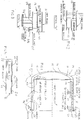
- the apparatus includes an outer tubular vessel 10 an inner tubular vessel 11, a membrane carrier 12 which is mounted on the outer surface of the inner vessel and a spiral baffle 13 which is mounted on the inner surface of the outer vessel.
- the outer and inner tubular vessels are conveniently cylindrical but other cross section forms could be used as desired.
- Each vessel 10, 11 is closed at one end by a dishing (walls 14, 15), the wall of the inner vessel having, in this embodiment a deeper curvature so that the space between the walls forms a passage 16 which narrows towards the crown of the domes.
- the vessels are disposed with their longitudinal axes horizontal, but can be mounted vertically should the process site determine otherwise.
- a pervaporator membrane 20 is laid over the membrane carrier 12 which, as illustrated in Fig 4 comprises a perforated drum 21 to which is attached wire cloth 22.
- the gauge and weave of the cloth are selected to produce the desired result.
- the drum 21 is an assembly which is mounted over blocking rings 23, 24 on the outer surface of the inner vessel, one ring 23 being at one end and the other 24 being mid way of the length of the vessel. At the other end is a flange 25 and the drum assembly includes a portion which is mounted over the central ring 24 and the flange 25.
- the membrane 20 is in the form of a long length of membrane material which is spirally wound around the carrier 12 from one end to the other.
- a pad (not shown) may be attached to a trunnion to facilitate the winding of the membrane around the carrier.
- the membrane material is sealed either by heat or chemically.
- the membrane rests on blocking ring 23 and against the flange 25 and clamping devices (not shown) seal the membrane.
- the inner vessel also has, in its end wall 15 a fluid feed pipe 26 which opens into the passage 16 between the ends 14, 15 of the vessels 10, 11.
- the outer vessel 10 has a flange 28, Fig 3 around its outer end to engage with the flange 25 of the inner vessel for bolting the two vessels together at 29 when the inner vessel 11 is located within the outer vessel 10.
- the annular space between the membrane carrier 12 and the wall of the inner vessel forms a vacuum chamber 30 via a vacuum connection port 31, (Fig 1) in the inner vessel 11.
- a relief valve and vacuum gauge 32, (Fig 3) in the flange 25 is provided to break the vacuum when required.
- the outer vessel 10 also has two ports 33, 34 adjacent to its outer end, these ports being diametrically opposed, in this embodiment.
- One port 33 extends through the upper surface of the vessel and the other 34 through the lower surface, the upper port 33 being for product outlet and the lower port 34 being a drain.
- the inner vessel also carries a port 35, on its upper surface for vapour connections.
- the volume inside the composite vessel is open to atmosphere and can be used to house equipment associated with the pervaporisation process such as pumps, heat exchangers, valves, pipes etc., thus making the complete assembly compact.
- a frame (not shown) may be provided to ensure alignment of the two vessels, thus preventing damage to the surface of the membrane during assembly.
- fluid such as ethyl alcohol and water is fed into passage 16 and is then guided by the baffles 13 to run spirally over the membrane and achieve maximum surface contact.
- the fluid is under pressure, e.g. 30 p.s.i. with a vacuum (equivalent to 15 p.s.i.) drawn on the underside of the membrane to give a total a pressure gradient across the membrane of, e.g. 45 p.s.i.
- FIGS 5 to 8 show an alternative embodiment of the present invention in which the inner vessel 11 is replaced by a plurality of cylindrical vessels 11.
- the outer vessel 10 is replaced by a feed-in chamber which interconnects to the feed-out chamber by a series of tubular feed pipes. This arrangement provides for a constant velocity flow of feed over the membrane surface of smaller annulus area than that so far obtainable on the single tubular unit.
- the membrane carrier is of similar design to that of the above described embodiment but would be engineered as a flanged cartridge unit, open at the flanged end, and closed at the other.
- the cartridge would be inserted at the lower end of the unit so that any entrained liquid would drain into the vacuum chamber, otherwise the cartridge would flood.
- the membrane cartridges may be dismantled from the multitube unit by unbolting the lower chamber, and removing the cartridges for inspection of surface coating or if required replacement of these by membranes of different coatings to suit other separations.
- the cartridges may be produced to closer dimension tolerances, and coatings of various types held in store to suit particular applications.
- the above unit may be serviced by a feed tank and external heat exchanger similar to that in the single tubular unit.
- Another advantage of the multi-tubular unit is that for the same volume of plant, the surface area of 3 M2 for the single unit, would be increased to 6 M2.
- the multi-tubular configuration by have an internal condensing coil and baffle arrangement located in the lower vacuum chamber whereby the condensate would drain into the receiver as per the single pervaporator.
- cylindrical construction allows for variations in length and diameter thus providing a wide range of sizes of exposed membrane area.
- single modules can be stacked up on gantries/steel decks and so interconnect with each other to provide complete processing plants.
- inlet pipes 26, outlet pipes 33 and vapour outlets 35 may be provided.
- the perforated membrane may be provided in multiple banks.
- fluid may be fed into passage 16 at one or more starting positions and means may be mounted on the spiral baffle 13 to alter the flow rate, of fluid through the passage 16.
Landscapes
- Chemical & Material Sciences (AREA)
- Chemical Kinetics & Catalysis (AREA)
- Engineering & Computer Science (AREA)
- Water Supply & Treatment (AREA)
- Analytical Chemistry (AREA)
- General Chemical & Material Sciences (AREA)
- Oil, Petroleum & Natural Gas (AREA)
- Separation Using Semi-Permeable Membranes (AREA)
- Degasification And Air Bubble Elimination (AREA)
Applications Claiming Priority (2)
| Application Number | Priority Date | Filing Date | Title |
|---|---|---|---|
| GB919116017A GB9116017D0 (en) | 1991-07-25 | 1991-07-25 | Apparatus for a method of fluid separation |
| GB9116017 | 1991-07-25 |
Publications (2)
| Publication Number | Publication Date |
|---|---|
| EP0524769A2 true EP0524769A2 (de) | 1993-01-27 |
| EP0524769A3 EP0524769A3 (de) | 1993-03-03 |
Family
ID=10698924
Family Applications (1)
| Application Number | Title | Priority Date | Filing Date |
|---|---|---|---|
| EP19920306510 Withdrawn EP0524769A3 (de) | 1991-07-25 | 1992-07-16 | Vorrichtung für ein Fluidabtrennungsverfahren |
Country Status (5)
| Country | Link |
|---|---|
| EP (1) | EP0524769A3 (de) |
| KR (1) | KR930001962A (de) |
| BR (1) | BR9202791A (de) |
| CA (1) | CA2074311A1 (de) |
| GB (1) | GB9116017D0 (de) |
Cited By (2)
| Publication number | Priority date | Publication date | Assignee | Title |
|---|---|---|---|---|
| EP1819007A1 (de) * | 2006-02-10 | 2007-08-15 | Samsung SDI Co., Ltd. | Gas-Flüssigkeits-Trenner und damit versehenes Brennstoffzellensystem |
| CN111424306A (zh) * | 2020-04-13 | 2020-07-17 | 厦门通富微电子有限公司 | 一种气泡剥离装置及电镀液电镀系统 |
Family Cites Families (6)
| Publication number | Priority date | Publication date | Assignee | Title |
|---|---|---|---|---|
| US3483990A (en) * | 1967-03-06 | 1969-12-16 | Beckman Instruments Inc | Dialyzer apparatus |
| US3578175A (en) * | 1969-04-23 | 1971-05-11 | Universal Water Corp | Helically wound semipermeable membrane |
| US3722694A (en) * | 1970-06-10 | 1973-03-27 | Romicon Inc | Filtration device |
| US3768660A (en) * | 1972-02-14 | 1973-10-30 | Raypak Inc | Reverse osmosis cell with turbulator means |
| SE7812682L (sv) * | 1978-01-05 | 1979-07-06 | Kuesters Eduard | Filteranordning |
| AU528590B2 (en) * | 1979-09-07 | 1983-05-05 | Union Carbide Corporation | Ultrafiltration and reverse osmosis device |
-
1991
- 1991-07-25 GB GB919116017A patent/GB9116017D0/en active Pending
-
1992
- 1992-07-16 EP EP19920306510 patent/EP0524769A3/de not_active Withdrawn
- 1992-07-21 CA CA002074311A patent/CA2074311A1/en not_active Abandoned
- 1992-07-22 BR BR929202791A patent/BR9202791A/pt not_active Application Discontinuation
- 1992-07-24 KR KR1019920013319A patent/KR930001962A/ko not_active Withdrawn
Cited By (2)
| Publication number | Priority date | Publication date | Assignee | Title |
|---|---|---|---|---|
| EP1819007A1 (de) * | 2006-02-10 | 2007-08-15 | Samsung SDI Co., Ltd. | Gas-Flüssigkeits-Trenner und damit versehenes Brennstoffzellensystem |
| CN111424306A (zh) * | 2020-04-13 | 2020-07-17 | 厦门通富微电子有限公司 | 一种气泡剥离装置及电镀液电镀系统 |
Also Published As
| Publication number | Publication date |
|---|---|
| KR930001962A (ko) | 1993-02-22 |
| BR9202791A (pt) | 1993-03-30 |
| GB9116017D0 (en) | 1991-09-11 |
| EP0524769A3 (de) | 1993-03-03 |
| CA2074311A1 (en) | 1993-01-26 |
Similar Documents
| Publication | Publication Date | Title |
|---|---|---|
| AU585177B2 (en) | Hollow fibre filter cartridge and header | |
| EP0238737B1 (de) | Membranstapeleinheit für eine Flüssigkeitstrennungsscheibe | |
| CN106422783B (zh) | 高效开放式网管流道反渗透膜组件 | |
| US4461707A (en) | Ultrafiltration and reverse osmosis tubular membrane module | |
| US5525220A (en) | Filtration equipment | |
| EP0873779B1 (de) | Modul mit selektiv durchlässigen Membranen | |
| CA2670799C (en) | Multi-tube pressure vessel | |
| US4062771A (en) | Apparatus and process for membrane filtration | |
| US11964236B2 (en) | Filter device, and method of assembly | |
| JPS6351722B2 (de) | ||
| EP0513207A1 (de) | Spiralförmig gewickelte membrantrennvorrichtung mit zufuhr- und permeat/ausspülfluidum-strömungskontrolle | |
| US8945387B2 (en) | Hollow fiber membrane module for use in a tubular pressure vessel | |
| US3953334A (en) | Fluid fractionating apparatus | |
| CA2100647A1 (en) | Multi-element housing | |
| US3872015A (en) | Apparatus for separating fluids into two fractions by means of semipermeable membranes | |
| EP0524769A2 (de) | Vorrichtung für ein Fluidabtrennungsverfahren | |
| EP0217568B1 (de) | Vorrichtung zur Behandlung von Flüssigkeiten | |
| US3805881A (en) | Fluid heat exchange system | |
| JP7130698B2 (ja) | 薄膜を用いて圧力下にある液体混合物を濾過し、分離する装置 | |
| JPH0258963B2 (de) | ||
| CN1015220B (zh) | 锅炉过滤器壳体中的过滤部件 | |
| CA1170996A (en) | Ultrafiltration and reverse osmosis tubular membrane module | |
| USH2168H1 (en) | Arrangement and construction of an element bundling module | |
| WO2009082392A1 (en) | Four-port gas separation membrane module assembly | |
| JPS62244405A (ja) | 膜分離装置用渦巻型膜エレメント |
Legal Events
| Date | Code | Title | Description |
|---|---|---|---|
| PUAI | Public reference made under article 153(3) epc to a published international application that has entered the european phase |
Free format text: ORIGINAL CODE: 0009012 |
|
| PUAL | Search report despatched |
Free format text: ORIGINAL CODE: 0009013 |
|
| AK | Designated contracting states |
Kind code of ref document: A2 Designated state(s): AT BE CH DE DK ES FR GB GR IT LI LU MC NL PT SE |
|
| AK | Designated contracting states |
Kind code of ref document: A3 Designated state(s): AT BE CH DE DK ES FR GB GR IT LI LU MC NL PT SE |
|
| STAA | Information on the status of an ep patent application or granted ep patent |
Free format text: STATUS: THE APPLICATION IS DEEMED TO BE WITHDRAWN |
|
| 18D | Application deemed to be withdrawn |
Effective date: 19930904 |