EP0525314A1 - Pompe à hydraulique - Google Patents
Pompe à hydraulique Download PDFInfo
- Publication number
- EP0525314A1 EP0525314A1 EP92108137A EP92108137A EP0525314A1 EP 0525314 A1 EP0525314 A1 EP 0525314A1 EP 92108137 A EP92108137 A EP 92108137A EP 92108137 A EP92108137 A EP 92108137A EP 0525314 A1 EP0525314 A1 EP 0525314A1
- Authority
- EP
- European Patent Office
- Prior art keywords
- piston
- sealing ring
- hydraulic pump
- working space
- pump
- Prior art date
- Legal status (The legal status is an assumption and is not a legal conclusion. Google has not performed a legal analysis and makes no representation as to the accuracy of the status listed.)
- Granted
Links
- 238000007789 sealing Methods 0.000 claims abstract description 37
- 230000005540 biological transmission Effects 0.000 abstract 1
- 239000012530 fluid Substances 0.000 description 6
- 230000000694 effects Effects 0.000 description 5
- 230000006835 compression Effects 0.000 description 3
- 238000007906 compression Methods 0.000 description 3
- 238000004519 manufacturing process Methods 0.000 description 3
- 230000000903 blocking effect Effects 0.000 description 2
- 238000001816 cooling Methods 0.000 description 2
- 239000007788 liquid Substances 0.000 description 2
- 230000004323 axial length Effects 0.000 description 1
- 239000013536 elastomeric material Substances 0.000 description 1
- 238000000034 method Methods 0.000 description 1
- 238000005086 pumping Methods 0.000 description 1
Images
Classifications
-
- F—MECHANICAL ENGINEERING; LIGHTING; HEATING; WEAPONS; BLASTING
- F04—POSITIVE - DISPLACEMENT MACHINES FOR LIQUIDS; PUMPS FOR LIQUIDS OR ELASTIC FLUIDS
- F04B—POSITIVE-DISPLACEMENT MACHINES FOR LIQUIDS; PUMPS
- F04B53/00—Component parts, details or accessories not provided for in, or of interest apart from, groups F04B1/00 - F04B23/00 or F04B39/00 - F04B47/00
- F04B53/14—Pistons, piston-rods or piston-rod connections
- F04B53/143—Sealing provided on the piston
-
- B—PERFORMING OPERATIONS; TRANSPORTING
- B60—VEHICLES IN GENERAL
- B60T—VEHICLE BRAKE CONTROL SYSTEMS OR PARTS THEREOF; BRAKE CONTROL SYSTEMS OR PARTS THEREOF, IN GENERAL; ARRANGEMENT OF BRAKING ELEMENTS ON VEHICLES IN GENERAL; PORTABLE DEVICES FOR PREVENTING UNWANTED MOVEMENT OF VEHICLES; VEHICLE MODIFICATIONS TO FACILITATE COOLING OF BRAKES
- B60T8/00—Arrangements for adjusting wheel-braking force to meet varying vehicular or ground-surface conditions, e.g. limiting or varying distribution of braking force
- B60T8/32—Arrangements for adjusting wheel-braking force to meet varying vehicular or ground-surface conditions, e.g. limiting or varying distribution of braking force responsive to a speed condition, e.g. acceleration or deceleration
- B60T8/34—Arrangements for adjusting wheel-braking force to meet varying vehicular or ground-surface conditions, e.g. limiting or varying distribution of braking force responsive to a speed condition, e.g. acceleration or deceleration having a fluid pressure regulator responsive to a speed condition
- B60T8/40—Arrangements for adjusting wheel-braking force to meet varying vehicular or ground-surface conditions, e.g. limiting or varying distribution of braking force responsive to a speed condition, e.g. acceleration or deceleration having a fluid pressure regulator responsive to a speed condition comprising an additional fluid circuit including fluid pressurising means for modifying the pressure of the braking fluid, e.g. including wheel driven pumps for detecting a speed condition, or pumps which are controlled by means independent of the braking system
- B60T8/4031—Pump units characterised by their construction or mounting
-
- B—PERFORMING OPERATIONS; TRANSPORTING
- B60—VEHICLES IN GENERAL
- B60T—VEHICLE BRAKE CONTROL SYSTEMS OR PARTS THEREOF; BRAKE CONTROL SYSTEMS OR PARTS THEREOF, IN GENERAL; ARRANGEMENT OF BRAKING ELEMENTS ON VEHICLES IN GENERAL; PORTABLE DEVICES FOR PREVENTING UNWANTED MOVEMENT OF VEHICLES; VEHICLE MODIFICATIONS TO FACILITATE COOLING OF BRAKES
- B60T8/00—Arrangements for adjusting wheel-braking force to meet varying vehicular or ground-surface conditions, e.g. limiting or varying distribution of braking force
- B60T8/32—Arrangements for adjusting wheel-braking force to meet varying vehicular or ground-surface conditions, e.g. limiting or varying distribution of braking force responsive to a speed condition, e.g. acceleration or deceleration
- B60T8/34—Arrangements for adjusting wheel-braking force to meet varying vehicular or ground-surface conditions, e.g. limiting or varying distribution of braking force responsive to a speed condition, e.g. acceleration or deceleration having a fluid pressure regulator responsive to a speed condition
- B60T8/42—Arrangements for adjusting wheel-braking force to meet varying vehicular or ground-surface conditions, e.g. limiting or varying distribution of braking force responsive to a speed condition, e.g. acceleration or deceleration having a fluid pressure regulator responsive to a speed condition having expanding chambers for controlling pressure, i.e. closed systems
- B60T8/4275—Pump-back systems
Definitions
- the invention relates to a hydraulic pump, in particular for a hydraulic brake control system according to the preamble of claim 1.
- the contact pressure force which is effective on the wall of the pump cylinder can be set in proportion to the pressure in the working space. This ensures that, during operation of the pump, the pump pressure built up in the working space acts on the sealing ring in such a way that a pressure cushion which is effective in the circumferential direction increases the sealing force on the cylinder wall.
- the pump when the pump is at a standstill, there is no hydrodynamic servo force which expands the sealing ring radially, so that a pressure equalization between the working space and the leakage space can take place over the groove base due to the reduced sealing ring effect (middle position in the groove).
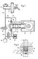
- the hydraulic pump shown in FIG. 1 has a pump housing 1 with a pump cylinder 2, a piston 3 and an eccentric gear 4.
- the piston 3 is axially displaceably mounted in a piston bore 5 of the pump cylinder 2 and is pressed against the stroke curve of the eccentric gear 4 by a compression spring 6 supported on the housing 1.
- the piston 3 delimits with its end facing away from the eccentric gear 4 a working space 7 formed by the closed end of the cylinder bores 5, which is connected to an inlet valve 8 and an outlet valve, which are shown in the drawing as spring-loaded check valves.
- the piston 3 has three differently shaped sections within the cylinder bore 5.
- the section 10 adjacent to the working space 7 is provided with a sealing ring 24 which ensures the necessary sealing of the sliding surfaces between the cylinder bore 5 and the piston 3 during the pump run.
- the middle section of the piston 3 is provided with an annular groove through which an annular space 11 is formed, the axial length of which corresponds to the piston stroke.
- the portion of the piston 3 which is adjacent to the eccentric gear 4 has, within the piston bore 5, a sealing ring 12 made of elastomeric material, by means of which the annular space 11 is sealed off from the housing space 13 which accommodates the eccentric gear 4.
- the outlet valve 9 of the hydraulic pump is connected via a delivery line 14 to a brake circuit 15 of a brake pressure sensor 16 of a hydraulic, slip-controlled vehicle brake system.
- the annular space 11 is also connected to the delivery line 14 via a line 17.
- a wheel brake 18 is connected to the brake circuit 15 and can be controlled via two solenoid valves 19, 20. From the closed solenoid valve 20 in the basic position, a delivery line 21 leads to the inlet valve 8 of the hydraulic pump. This delivery line 21 is also connected to a low pressure accumulator 22.
- the brake pressure transmitter 16 and the units connected to it via the brake circuit 15 are filled with brake fluid and vented. Air pockets are undesirable because they increase the volume required when the brake is actuated.
- the ar are therefore also filled with brake fluid beitsraum 7 and the annular space 11 of the hydraulic pump.
- the pressure specified by the low-pressure accumulator 22 prevails in the delivery line 21, which is separated from the brake circuit 15 by the closed solenoid valve 20.
- the pressure in the work space 7 can be different. It depends on the opening pressures of the inlet valve 8 and the outlet valve 9.
- the annular space 11 which is permanently connected to the delivery line 14, prevents a vacuum from being created in the working space 7, for which purpose brake fluid flows into the working space 7 via the sealing ring 24 of the piston 3.
- the hydraulic pump conveys the fluid via the open solenoid valve 20 from the wheel brake 18 into the part of the brake circuit 15 connected to the brake pressure transmitter 6, the solenoid valve 19, which is de-energized in the basic position, being in the position blocking the brake circuit 15 .
- the solenoid valve 19 which is de-energized in the basic position, being in the position blocking the brake circuit 15 .
- annular space 11 can be connected to the pump inlet-side delivery line 21 via a line 23 shown in broken lines.
- This configuration also reliably prevents the ingress of air into the working space 7, the opening pressure of the inlet valve 8 being chosen so large that the pumping speed of the hydraulic pump is not sufficient to lower the pressure in the delivery line 21 below atmospheric pressure.
- FIG. 2 shows the hydrodynamic pressure force effective on the sealing ring 24 during the compression stroke carried out by the piston 3 to the right.
- the sealing ring 24 is initially supported as a result of the wall friction acting between the pump cylinder 2 and the sealing ring 24 on the right shoulder of the piston ring groove 25, so that the entire axial ring play (play s) expediently takes effect on the left shoulder of the piston ring groove 25.
- the hydrodynamic circumferential force which thereby acts on the inner wall of the sealing ring 24 expands the sealing ring 24 in order to press it against the wall of the pump cylinder 2.
- the groove base 26 and thus the sealing ring 24 are relieved of pressure as a result of the pressure drop in the working space 7, so that the sealing ring 24 assumes its original relaxed shape (nominal diameter).
- the liquid pressure present on the right and left sides of the sealing ring 24 sets the latter in the groove in a central position as soon as the pressure in the working space 7 drops, for example as a result of the cooling process of the pump.
- the pressure medium present in the annular space 11 can then flow unhindered over the released right shoulder 27 of the piston ring groove 25 into the groove base 26 and from there over the left shoulder 28 of the piston ring groove 25 in the direction of the working space 7 in order to produce the pressure compensation.
- sealing ring 24 is independent of the direction of the piston movement and thus of the pressure medium flow, so that the same sealing effect also occurs when pressure is applied contrary to the illustration - in this case on the left shoulder 28 .
- Sheathed seals, slotted seals and spiral baking rings are particularly suitable as sealing rings, to give only a small overview of the large number of available sealing ring shapes. Due to the special seal described, the cost-intensive precision tolerance of the piston running surface can be dispensed with.
Landscapes
- Engineering & Computer Science (AREA)
- Mechanical Engineering (AREA)
- Physics & Mathematics (AREA)
- Fluid Mechanics (AREA)
- Transportation (AREA)
- General Engineering & Computer Science (AREA)
- Valves And Accessory Devices For Braking Systems (AREA)
- Regulating Braking Force (AREA)
- Details Of Reciprocating Pumps (AREA)
Applications Claiming Priority (2)
| Application Number | Priority Date | Filing Date | Title |
|---|---|---|---|
| DE4125027 | 1991-07-29 | ||
| DE4125027A DE4125027A1 (de) | 1991-07-29 | 1991-07-29 | Hydraulikpumpe |
Publications (2)
| Publication Number | Publication Date |
|---|---|
| EP0525314A1 true EP0525314A1 (fr) | 1993-02-03 |
| EP0525314B1 EP0525314B1 (fr) | 1995-03-08 |
Family
ID=6437204
Family Applications (1)
| Application Number | Title | Priority Date | Filing Date |
|---|---|---|---|
| EP92108137A Revoked EP0525314B1 (fr) | 1991-07-29 | 1992-05-14 | Pompe à hydraulique |
Country Status (2)
| Country | Link |
|---|---|
| EP (1) | EP0525314B1 (fr) |
| DE (2) | DE4125027A1 (fr) |
Families Citing this family (3)
| Publication number | Priority date | Publication date | Assignee | Title |
|---|---|---|---|---|
| DE19708142A1 (de) * | 1997-02-28 | 1998-09-03 | Itt Mfg Enterprises Inc | Hydraulische Bremsanlage, insbesondere für Kraftfahrzeuge |
| DE19709586A1 (de) * | 1997-03-08 | 1998-09-10 | Itt Mfg Enterprises Inc | Hydraulische Pumpe mit weggsteuertem Saugventil |
| WO2024134352A1 (fr) * | 2022-12-23 | 2024-06-27 | 70442 ロベルト•ボッシュ•ゲゼルシャフト•ミト•ベシュレンクテル•ハフツング | Unité de commande hydraulique et véhicule |
Citations (3)
| Publication number | Priority date | Publication date | Assignee | Title |
|---|---|---|---|---|
| DE3701168A1 (de) * | 1987-01-16 | 1988-07-28 | Hemscheidt Maschf Hermann | Kolbenmaschine |
| EP0327218A2 (fr) * | 1988-01-30 | 1989-08-09 | LUCAS INDUSTRIES public limited company | Système d'antiblocage de freinage hydraulique |
| DE4130729A1 (de) * | 1990-10-16 | 1992-04-23 | Teves Gmbh Alfred | Bremsdruckregelvorrichtung fuer eine hydraulische kraftfahrzeugbremsanlage |
Family Cites Families (9)
| Publication number | Priority date | Publication date | Assignee | Title |
|---|---|---|---|---|
| US2615769A (en) * | 1947-07-19 | 1952-10-28 | Byron H Barnes | Slush pump piston |
| DE1897759U (de) * | 1961-01-11 | 1964-07-30 | Fiat Spa | Fluessigkeitspumpe, insbesondere zur verwendung als hauptzylinder in hydraulischen uebertragungssystemen bei kraftfahrzeugen. |
| DE2838918A1 (de) * | 1978-09-07 | 1980-05-22 | Bosch Gmbh Robert | Hydraulisches druckbeschaffungssystem |
| DE3041933A1 (de) * | 1980-11-06 | 1982-06-09 | Speck-Kolbenpumpen-Fabrik Otto Speck Kg, 8192 Geretsried | Hochdruckpumpe |
| GB8512610D0 (en) * | 1985-05-18 | 1985-06-19 | Lucas Ind Plc | Hydraulic anti-skid braking systems |
| DE3740516C2 (de) * | 1987-11-30 | 1999-04-15 | Teves Gmbh Alfred | Blockiergeschützte Bremsanlage |
| DE3807552A1 (de) * | 1988-03-08 | 1989-09-21 | Teves Gmbh Alfred | Blockiergeschuetzte bremsanlage |
| DE8814552U1 (de) * | 1988-11-22 | 1990-03-22 | Robert Bosch Gmbh, 7000 Stuttgart | Kolben für eine hydrostatische Maschine |
| JPH02132874U (fr) * | 1989-04-12 | 1990-11-05 |
-
1991
- 1991-07-29 DE DE4125027A patent/DE4125027A1/de not_active Withdrawn
-
1992
- 1992-05-14 DE DE59201586T patent/DE59201586D1/de not_active Revoked
- 1992-05-14 EP EP92108137A patent/EP0525314B1/fr not_active Revoked
Patent Citations (3)
| Publication number | Priority date | Publication date | Assignee | Title |
|---|---|---|---|---|
| DE3701168A1 (de) * | 1987-01-16 | 1988-07-28 | Hemscheidt Maschf Hermann | Kolbenmaschine |
| EP0327218A2 (fr) * | 1988-01-30 | 1989-08-09 | LUCAS INDUSTRIES public limited company | Système d'antiblocage de freinage hydraulique |
| DE4130729A1 (de) * | 1990-10-16 | 1992-04-23 | Teves Gmbh Alfred | Bremsdruckregelvorrichtung fuer eine hydraulische kraftfahrzeugbremsanlage |
Also Published As
| Publication number | Publication date |
|---|---|
| DE4125027A1 (de) | 1993-02-04 |
| DE59201586D1 (de) | 1995-04-13 |
| EP0525314B1 (fr) | 1995-03-08 |
Similar Documents
| Publication | Publication Date | Title |
|---|---|---|
| DE69324803T2 (de) | Axialschubausgleich für schraubenverdichter | |
| DE3629065C2 (fr) | ||
| DE3711979A1 (de) | Taumelscheibenkompressor mit variabler foerderleistung | |
| DE3142230A1 (de) | Mehrzylinder-kompressor | |
| DE2552256A1 (de) | Pumpe oder hydromotor | |
| WO1992004216A1 (fr) | Pompe a pistons | |
| DE1924417A1 (de) | Hubsteuerung fuer hydraulische Pumpen | |
| DE4316986A1 (de) | Kolbenpumpe | |
| DE2841084A1 (de) | Verdraengerpumpe mit veraenderlicher foerdermenge | |
| EP0505539B1 (fr) | Regulateur de la pression des freins pour systemes hydrauliques de freinage de vehicules a moteur | |
| DE102016215311A1 (de) | Hydraulischer Antrieb | |
| DE3921790A1 (de) | Hydrostatische verdraengermaschine | |
| EP0525314B1 (fr) | Pompe à hydraulique | |
| DE2504562C3 (de) | Hydrostatische Axialkolbenpumpe | |
| DE3102506A1 (de) | "kolbenpumpe mit geregelter foerderleistung" | |
| DE3206613A1 (de) | Drucksteigernde kolbenpumpe | |
| DE19827970A1 (de) | Regeleinrichtung für Hydraulikpumpen | |
| DE4444381A1 (de) | Druckübersetzer | |
| DE102009039829A1 (de) | Hydrostatische Axialkolbenpumpe, insbesondere Schrägscheibenpumpe | |
| EP1283365A2 (fr) | Moteur hydraulique avec frein intégré | |
| DE3511168C2 (fr) | ||
| DE102009060188A1 (de) | Verstellventil für die Verstellung des Fördervolumens einer Verdrängerpumpe mit Kaltstartfunktion | |
| DE19859442C1 (de) | Hydrostatische Kolbenmaschine | |
| AT521675B1 (de) | Hydraulisches Steuerventil für eine längenverstellbare Pleuelstange mit zwei stirnseitigen Steuerkolben | |
| DE2554037A1 (de) | Dichtungsanordnung zum abdichten von relativ zueinander bewegten maschinenteilen bei hohen druecken |
Legal Events
| Date | Code | Title | Description |
|---|---|---|---|
| PUAI | Public reference made under article 153(3) epc to a published international application that has entered the european phase |
Free format text: ORIGINAL CODE: 0009012 |
|
| 17P | Request for examination filed |
Effective date: 19920514 |
|
| AK | Designated contracting states |
Kind code of ref document: A1 Designated state(s): DE FR GB |
|
| RAP1 | Party data changed (applicant data changed or rights of an application transferred) |
Owner name: ITT AUTOMOTIVE EUROPE GMBH |
|
| 17Q | First examination report despatched |
Effective date: 19931203 |
|
| GRAA | (expected) grant |
Free format text: ORIGINAL CODE: 0009210 |
|
| AK | Designated contracting states |
Kind code of ref document: B1 Designated state(s): DE FR GB |
|
| GBT | Gb: translation of ep patent filed (gb section 77(6)(a)/1977) |
Effective date: 19950315 |
|
| REF | Corresponds to: |
Ref document number: 59201586 Country of ref document: DE Date of ref document: 19950413 |
|
| ET | Fr: translation filed | ||
| PLBI | Opposition filed |
Free format text: ORIGINAL CODE: 0009260 |
|
| 26 | Opposition filed |
Opponent name: FIRMA CARL FREUDENBERG Effective date: 19950810 |
|
| PLBI | Opposition filed |
Free format text: ORIGINAL CODE: 0009260 |
|
| 26 | Opposition filed |
Opponent name: LUCAS AUTOMOTIVE LIMITED Effective date: 19951123 Opponent name: FIRMA CARL FREUDENBERG Effective date: 19950810 |
|
| PLBF | Reply of patent proprietor to notice(s) of opposition |
Free format text: ORIGINAL CODE: EPIDOS OBSO |
|
| PGFP | Annual fee paid to national office [announced via postgrant information from national office to epo] |
Ref country code: GB Payment date: 19960422 Year of fee payment: 5 |
|
| PGFP | Annual fee paid to national office [announced via postgrant information from national office to epo] |
Ref country code: FR Payment date: 19960506 Year of fee payment: 5 |
|
| PGFP | Annual fee paid to national office [announced via postgrant information from national office to epo] |
Ref country code: DE Payment date: 19960508 Year of fee payment: 5 |
|
| PLBF | Reply of patent proprietor to notice(s) of opposition |
Free format text: ORIGINAL CODE: EPIDOS OBSO |
|
| PLBF | Reply of patent proprietor to notice(s) of opposition |
Free format text: ORIGINAL CODE: EPIDOS OBSO |
|
| RDAH | Patent revoked |
Free format text: ORIGINAL CODE: EPIDOS REVO |
|
| RDAG | Patent revoked |
Free format text: ORIGINAL CODE: 0009271 |
|
| STAA | Information on the status of an ep patent application or granted ep patent |
Free format text: STATUS: PATENT REVOKED |
|
| GBPR | Gb: patent revoked under art. 102 of the ep convention designating the uk as contracting state |
Free format text: 961114 |
|
| 27W | Patent revoked |
Effective date: 19961114 |