EP0525404B1 - Elektrodenfassung von Elektrodentragarmen mit Kontaktbacke - Google Patents
Elektrodenfassung von Elektrodentragarmen mit Kontaktbacke Download PDFInfo
- Publication number
- EP0525404B1 EP0525404B1 EP92110930A EP92110930A EP0525404B1 EP 0525404 B1 EP0525404 B1 EP 0525404B1 EP 92110930 A EP92110930 A EP 92110930A EP 92110930 A EP92110930 A EP 92110930A EP 0525404 B1 EP0525404 B1 EP 0525404B1
- Authority
- EP
- European Patent Office
- Prior art keywords
- contact
- electrode
- pieces
- contact jaw
- jaw
- Prior art date
- Legal status (The legal status is an assumption and is not a legal conclusion. Google has not performed a legal analysis and makes no representation as to the accuracy of the status listed.)
- Expired - Lifetime
Links
- 210000000078 claw Anatomy 0.000 description 1
- 239000000498 cooling water Substances 0.000 description 1
- 230000001419 dependent effect Effects 0.000 description 1
- 230000013011 mating Effects 0.000 description 1
- 230000007704 transition Effects 0.000 description 1
Images


Classifications
-
- H—ELECTRICITY
- H05—ELECTRIC TECHNIQUES NOT OTHERWISE PROVIDED FOR
- H05B—ELECTRIC HEATING; ELECTRIC LIGHT SOURCES NOT OTHERWISE PROVIDED FOR; CIRCUIT ARRANGEMENTS FOR ELECTRIC LIGHT SOURCES, IN GENERAL
- H05B7/00—Heating by electric discharge
- H05B7/02—Details
- H05B7/10—Mountings, supports, terminals or arrangements for feeding or guiding electrodes
- H05B7/103—Mountings, supports or terminals with jaws
- H05B7/105—Mountings, supports or terminals with jaws comprising more than two jaws equally spaced along circumference, e.g. ring holders
Definitions
- the invention relates to an electrode holder of electrode support arms with a contact jaw of the type outlined in the preamble of claim 1.
- Such contact jaws can be found, for example, in AT-B-344 409 and GB-A-2 082 028.
- the contact jaw is provided on its underside with a claw, which fits into a recess in the contact piece attached to the contact jaw, which has a nose opposite the contact jaw by means of a nose that can be attached to the top of the contact jaw is set in a further recess in the contact piece inserting terminal block, which is combined with the contact jaw by a screw connection.
- the invention has for its object to design the attachment of the contact pieces on the contact jaw in a manner that allows a quicker replacement of the contact pieces and then also increases the adjustability of the contact pieces relative to the contact jaw.
- the object is achieved with a generic attachment of contact pieces to contact jaws of the electrode holder of electrode support arms in such a way that the contact pieces are provided on their end faces on their side facing away from their electrode contact surface with shoulders enclosing the contact jaw and the shoulders with one end of the circumference accessible, running on a circular arc with protruding on both sides over the bisector of the contact pieces Backdrop are provided, into which bearing bolts extending from the end faces of the contact jaw in alignment with the bisector of the receptacles for the contact pieces in the contact jaw are inserted.
- Embodiment of the invention result from the dependent claims 2-4.
- the screwless combination according to the invention of the contact pieces with the contact jaw allows, if necessary, an easy and quick exchange of the contact pieces with a comparatively large adjustment mobility of the contact pieces relative to the contact jaw.
- the division of the electrode contact surface of the contact pieces into a plurality of contact areas in connection with the adjustability of the contact pieces results in a sufficient current transfer from the contact jaw to the electrode even when using raw electrodes with an uneven outer surface.
- the use of raw electrodes instead of electrodes that are subjected to surface processing results in significant cost savings.
- the electrode contact areas of the contact pieces can be individually designed for the current transfer from the contact jaw to the electrode to be ensured in the special case while ensuring the high surface pressure that is then also required.
- a recess provided in the base of the receptacles for the contact pieces in the contact jaw and extending over their length ensures that the contact jaw is properly contacted by the contact pieces.
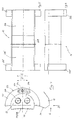
- the surface 211 (FIG. 3) of the contact jaw 21 facing the electrode takes a course on a circumference the electrode 31.
- half-shell-shaped recesses 212 (FIG. 3) running symmetrically to the longitudinal central axis 111 of the electrode support arm 11 are provided at a distance from the longitudinal central axis parallel to the electrode axis 311.
- these recesses 212 there are essentially semi-cylindrical contact pieces 22, delimited by the contact jaw 21, whose surface 221 facing the electrode 31 (FIGS. 3 and 4) takes a course corresponding to the radius of the electrode 31.
- the contact piece 22 is provided with shoulders 222, 222 'projecting towards the side facing away from its contact surface 221 facing the electrode 31, which in the installed state of the contact piece 22 has the contact jaw 21 on its end faces, that is to say on its top and on it Underside, overlap.
- these shoulders 222, 222 ' there is, starting from the inside, an arc-shaped course, one end 226 accessible from the circumference 223, link 224.
- link 224 projecting bolts 213 are inserted from the contact jaw 21 when the Contact pieces 22 on the contact jaw 21, which prevent an uncontrolled release of the contact pieces 22 from the contact jaw 21 when changing the electrodes.
- a recess 214 provided in the base of the receptacles 212 in the contact jaw 21 and extending over its length contributes to better contacting of the contact jaw 21 by the contact pieces 22.
- these pressure pieces 121 can be designed in a manner corresponding to the contact pieces 22 and assigned to the clamping bracket 12, as can be seen in FIGS. 1 and 2. With 216 and 229 cooling water channels in the contact jaw 21 and in the contact pieces 22 are designated.
Landscapes
- Physics & Mathematics (AREA)
- Engineering & Computer Science (AREA)
- Plasma & Fusion (AREA)
- Electrical Discharge Machining, Electrochemical Machining, And Combined Machining (AREA)
- Manipulator (AREA)
- Spinning Or Twisting Of Yarns (AREA)
- Coupling Device And Connection With Printed Circuit (AREA)
- Manufacturing Of Electrical Connectors (AREA)
- Gripping Jigs, Holding Jigs, And Positioning Jigs (AREA)
- Measuring Leads Or Probes (AREA)
Description
- Die Erfindung betrifft eine Elektrodenfassung von Elektrodentragarmen mit Kontaktbacke der im Oberbegriff des Patentanspruchs 1 umrissenen Gattung.
- Solche Kontaktbacken sind beispielsweise der AT-B-344 409 und der GB-A-2 082 028 zu entnehmen.
- Nach dem aus der AT-B-344 409 und dem aus der GB-A-2 082 028 entnehmbaren Stand der Technik ist es bekannt, Kontaktbacken bzw. stromführenden Klemmbacken im wesentlichen halbzylindrisch ausgebildete Kontaktstücke zuzuordnen, die sich unter Belassung eines Überstandes in entsprechende halbschalenförmige Aufnahmen in die Kontaktbacke einfügend mit der Kontaktbacke den Kontaktstücken eine gewisse Einstellbeweglichkeit belassend zusammengefaßt sind. Nach der AT-B-344 409 erfolgt die Zusammenfassung der Kontaktstücke mit der Kontaktbacke über Stiftschrauben bzw. Maschinenschrauben, die sich in der Kontaktbacke in einer Bohrung größeren Durchmessers als der Gewindestift der Schraubverbindung führend in das Kontaktstück geschraubt sind. Nach der GB-A-2 082 028 ist die Kontaktbacke an ihrer Unterseite mit einer Klaue versehen, die sich in einen Rücksprung im an der Kontaktbacke angesetzten Kontaktstück einfügt, das gegenüber der Kontaktbacke mittels einer an der Oberseite der Kontaktbacke ansetzbaren, sich mit einer Nase in einen weiteren Rücksprung im Kontaktstück einfügenden Klemmleiste festgelegt wird, die mit der Kontaktbacke durch eine Schraubverbindung zusammengefaßt wird. Aus beiden Lösungen resultiert eine nur sehr begrenzte Einstellbeweglichkeit der der Kontaktbacke zugeordneten Kontaktstücke. Außerdem bedarf es in beiden Fällen zum Auswechseln der Kontaktstücke des Lösens von Schraubverbindungen.
- Ausgehend vom Stand der Technik liegt der Erfindung die Aufgabe zugrunde, die Befestigung der Kontaktstücke an der Kontaktbacke in einer Weise auszubilden, die ein rascheres Auswechseln der Kontaktstücke ermöglicht und dann auch die Einstellbeweglichkeit der Kontaktstücke gegenüber der Kontaktbacke vergrößert.
- Die Aufgabe wird erfindungsgemäß bei einer gattungsgemäßen Befestigung von Kontaktstücken an Kontaktbacken der Elektrodenfassung von Elektrodentragarmen in der Weise gelöst, daß die Kontaktstücke an ihren Stirnseiten auf ihrer von ihrer Elektrodenanlagefläche abgekehrten Seite mit die Kontaktbacke einfassenden Schultern versehen sind und die Schultern mit einer einen Ends vom Umfang her zugänglichen, auf einem Kreisbogen mit beidseitigem Überstand über die Halbierende der Kontaktstücke verlaufenden Kulisse versehen sind, in die sich von den Stirnseiten der Kontaktbacke in der Flucht der Halbierenden der Aufnahmen für die Kontaktstücke in der Kontaktbacke ausgehende Lagerbolzen einfügen.
- Ausgestaltung der Erfindung ergeben sich aus den abhängigen Ansprüchen 2-4.
- Die erfindungsgemäße schraubenlose Zusammenfassung der Kontaktstücke mit der Kontaktbacke ermöglicht im Bedarfsfall in wünschenswerter Weise ein leichtes und schnelles Auswechseln der Kontaktstücke bei vergleichsweise großer Einstellbeweglichkeit der Kontaktstücke gegenüber der Kontaktbacke.
- Aus der Aufteilung der Elektrodenanlagefläche der Kontaktstücke in eine Mehrzahl von Kontaktbereiche in Verbindung mit der Einstellbeweglichkeit der Kontaktstücke resultiert auch bei einem Einsatz von Rohelektroden mit unebener Mantelfläche ein hinreichender Stromübergang von der Kontaktbacke auf die Elektrode. Der Einsatz von Rohelektroden anstelle von einer Oberflächenbearbeitung unterzogenen Elektroden erbringt eine ins Gewicht fallende Kostenersparnis. Die Elektrodenanlagebereiche der Kontaktstücke lassen sich durch Variierung der Breite des Rücksprungs zwischen den Anlageflächen individuell auf den im speziellen Fall sicherzustellenden Stromübergang von der Kontaktbacke auf die Elektrode unter Gewährleistung der dann auch erforderlichen hohen Flächenpressung auslegen. Ein im Grund der Aufnahmen für die Kontaktstücke in der Kontaktbacke vorgesehener, sich über deren Länge erstreckender Rücksprung stellt eine einwandfreie Kontaktierung der Kontaktbacke durch die Kontaktstücke sicher.
- In der Zeichnung ist die Erfindung anhand eines in ganz schematischer Weise dargestellten Ausführungsbeispieles weitergehend erläutert. Es zeigen:
- Figur 1
- einen Elektrodentragarm mit eingespannter Elektrode in Seitenansicht, abgebrochen,
- Figur 2
- den Elektrodentragarm in Fig. 1 in Draufsicht,
- Figur 3
- einen Auschnitt aus Fig. 2 in größerem Maßstab,
- Figur 4
- ein Bestandteil der Kontaktbacke bildende Kontaktstück in Draufsicht,
- Figur 5
- die Ansicht des Kontaktstücks in Richtung des Pfeiles A in Fig. 4,
- Figur 6
- die Ansicht des Kontaktstücks in Richtung des Pfeiles B in Fig. 4.
- Am freien Ende des in den Figuren 1 und 2 abgebrochen dargestellten Elektrodentragarms 11 befindet sich die Kontaktbacke 21, gegen die die Elektrode 31 mittels des in an sich bekannter Weise im Sinne des Pfeiles C anstellbaren Spannbügels 12 gepreßt wird.
- Die der Elektrode zugewandte Fläche 211 (Fig.3) der Kontaktbacke 21 nimmt einen Verlauf auf einem Umkreis um die Elektrode 31. In dieser Fläche 211 der Kontaktbacke 21 sind symmetrisch zur Längsmittelachse 111 des Elektrodentragarms 11 im Abstand von der Längsmittelachse parallel zur Elektrodenachse 311 verlaufende, halbschalenförmige Rücksprünge 212 (Fig. 3) vorgesehen. In diese Rücksprünge 212 fügen sich im wesentlichen halbzylindrisch Kontaktstücke 22, begrenzt über die Kontaktbacke 21 vorspringend ein, deren der Elektrode 31 zugewandte Fläche 221 (Figuren 3 und 4) einen dem Radius der Elektrode 31 entsprechenden Verlauf nimmt. An den Stirnseiten ist das Kontaktstück 22 mit nach der von seiner der Elektrode 31 zugewandten Anlagefläche 221 abgekehrten Seite hin vorspringenden Schultern 222, 222′ versehen, die im Einbauzustand des Kontaktstücks 22 die Kontaktbacke 21 an ihren Stirnseiten, also an ihrer Ober- und an ihrer Unterseite, übergreifen.In diesen Schultern 222, 222′ befindet sich ausgehend von ihrer Innenseite eine einen kreisbogenförmigen Verlauf nehmende, einen Ends 226 vom Umfang 223 her zugängliche Kulisse 224. In diese Kulisse 224 fügen sich aus der Kontaktbacke 21 vorspringende Bolzen 213 beim Ansetzen der Kontaktstücke 22 an der Kontaktbacke 21 ein, die ein unkontrolliertes Lösen der Kontaktstücke 22 von der Kontaktbacke 21 beim Elektrodenwechsel verhindern. Das Lösen eines solchen Kontaktstückes 22 von der Kontaktbacke 21 wird erst bei extremem Verschwenken des Kontaktstückes 22 gegenüber der Kontaktbake 21 im Sinne des Pfeiles D in Figur 4 möglich. Durch einen Rücksprung 227 in der der Elektrode 31 zugewandten Fläche 221 der Kontaktstücke 22 sind in den Endbereichen der Kontaktstücke 22 die Übergangskontakte bildende, gegen die Mantefläche 312 der Elektrode 31 zur Anlage kommende Anlagebereiche 228, 228′ ausgebildet. Diese Art und Weise der Kontaktierung der Elektrode 31 gestattet es, Rohelektroden, also oberflächig nicht bearbeitete Elektroden, einzusetzen, da die nach der Erfindung ausgebildeten Kontakte 228, 228′ in Verbindung mit der Einstellbeweglichkeit der Kontaktstücke 22 (Doppelpfeil D′ in Fig. 4) für den Stromübergang in die Elektrode 31 auch bei einer unebenen Elektrodenoberfläche 312 eine ausreichende Kontaktierung sicherstellen. Aus der Einsetzbarkeit von Rohelektroden resultiert eine ins Gewicht fallende Einsparung an Elektrodenkosten. Ein im Grund der Aufnahmen 212 in der Kontaktbacke 21 vorgesehener, sich über deren Länge erstreckender Rücksprung 214 trägt zu einer besseren Kontaktierung der Kontaktbacke 21 durch die Kontaktstücke 22 bei.
- Ist der Spannbügel 12 mit Druckstücken versehen, können diese Druckstücke 121 in einer den Kontaktstücken 22 entsprechenden Weise ausgebildet und dem Spannbügel 12 zugeordnet sein, wie das den Figuren 1 und 2 zu entnehmen ist. Mit 216 und 229 sind Kühlwasserkanäle in der Kontaktbacke 21 und in den Kontaktstücken 22 bezeichnet.
Claims (4)
- Elektrodenfassung (12) eines Elektrodentragarms (11) mit am freien Ende des Tragarms (11) angesetzten Kontaktbacke (21), die elektrodenseitig mit symmetrisch zur Längsmittelachse des Tragarms (11) angeordneten,parallel zur Elektrodenachse verlaufenden halbschalenförmigen Aufnahmen (212) versehen ist, in die im wesentlichen halbzylindrisch ausgebildete Kontaktstücke (22) mit Überstand über die Kontaktbacke (21) einstellbeweglich eingelagert sind, gegen die die Elektrode (31) zur Anlage kommt, dadurch gekennzeichnet, daß die Kontaktstücke (22) an ihren Stirnseiten auf ihrer von ihrer Elektrodenanlagefläche (221) abgekehrten Seite mit die Kontaktbacke (21) einfassenden Schultern (222, 222′) versehen sind und die Schultern (222, 222′) mit einer einen Ends vom Umfang her zugänglichen (226), auf einem Kreisbogen mit beidseitigem Überstand über die Halbierende der Kontaktstücke (22) verlaufenden Kulisse (224) zur Aufnahme eines von den Stirnseiten der Kontaktbacke (21) in der Flucht der Halbierenden der Aufnahmen (212) für die Kontaktstücke (22) in der Kontaktbacke (21) ausgehenden Lagerbolzens (213) versehen sind.
- Elektrodenfassung nach Anspruch 1, dadurch gekennzeichnet, daß die Kulisse (224) von der Innenseite der Schultern (222 222′) her in die Schultern (222, 222′) der Kontaktstücke (22) eingearbeitet sind.
- Elektrodenfassung nach Anspruch 1 oder Anspruch 2, dadurch gekennzeichnet, daß die der Elektrode (31) zugewandte Fläche der Kontaktstücke (22) mit einem zwei Anlagebereiche (228, 228′) ausbildenden Rücksprung (227) versehen ist.
- Elektrodenfassung nach einem der Ansprüche 1 bis 3, dadurch gekennzeichnet, daß die Aufnahmen (212) für die Kontaktstücke (22) in der Kontaktbacke (21) im Grund mit einem sich über ihre Länge erstreckenden Rücksprung (214) versehen sind.
Applications Claiming Priority (2)
| Application Number | Priority Date | Filing Date | Title |
|---|---|---|---|
| DE4122151 | 1991-07-04 | ||
| DE4122151A DE4122151A1 (de) | 1991-07-04 | 1991-07-04 | Elektrodenfassung eines elektrodentragarms |
Publications (2)
| Publication Number | Publication Date |
|---|---|
| EP0525404A1 EP0525404A1 (de) | 1993-02-03 |
| EP0525404B1 true EP0525404B1 (de) | 1994-08-10 |
Family
ID=6435425
Family Applications (1)
| Application Number | Title | Priority Date | Filing Date |
|---|---|---|---|
| EP92110930A Expired - Lifetime EP0525404B1 (de) | 1991-07-04 | 1992-06-27 | Elektrodenfassung von Elektrodentragarmen mit Kontaktbacke |
Country Status (4)
| Country | Link |
|---|---|
| EP (1) | EP0525404B1 (de) |
| AT (1) | ATE109937T1 (de) |
| DE (2) | DE4122151A1 (de) |
| ES (1) | ES2057950T3 (de) |
Cited By (2)
| Publication number | Priority date | Publication date | Assignee | Title |
|---|---|---|---|---|
| US8270139B2 (en) | 2010-09-16 | 2012-09-18 | General Electric Company | Adjustable arc electrode assembly and method of assembling |
| US9036309B2 (en) | 2010-09-16 | 2015-05-19 | General Electric Company | Electrode and plasma gun configuration for use with a circuit protection device |
Families Citing this family (1)
| Publication number | Priority date | Publication date | Assignee | Title |
|---|---|---|---|---|
| DE102004005051A1 (de) * | 2004-01-30 | 2005-08-18 | Arndt Dung | Am freien Ende eines Bestandteil eines Elektroofens bildenden Elektrodentragarms auswechselbar angeordnete Kontaktbacke |
Family Cites Families (9)
| Publication number | Priority date | Publication date | Assignee | Title |
|---|---|---|---|---|
| US3334170A (en) * | 1964-04-23 | 1967-08-01 | Alfred H Turner | Water cooled electrode head for electric furnace electrodes or the like |
| DE1565429B1 (de) * | 1966-07-26 | 1971-07-01 | Krupp Gmbh | Elektrodenfassunf für Lichtbogen¦fen |
| AT344409B (de) * | 1975-11-07 | 1978-07-25 | Elin Union Ag | Hochstrom-klemmeinrichtung |
| US4323717A (en) * | 1979-02-07 | 1982-04-06 | British Steel Corporation | Furnace electrode clamps |
| NO802263L (no) * | 1980-07-25 | 1982-01-26 | Elkem Spigerverket As | Elektrodeholder. |
| GB2082028A (en) * | 1980-08-05 | 1982-02-24 | British Steel Corp | Improvements in furnace electrode clamps |
| DE3212099C2 (de) * | 1982-04-01 | 1986-02-20 | Pfister Gmbh, 8900 Augsburg | Vorrichtung zum Messen einer Kraft |
| DE3517069A1 (de) * | 1985-05-11 | 1986-11-13 | Fried. Krupp Gmbh, 4300 Essen | Kontaktbacke einer elektrodenfassung |
| GB2207588A (en) * | 1987-07-07 | 1989-02-01 | Anglo Great Lakes Corp Plc | Arc-furnace clamp for graphite electrode |
-
1991
- 1991-07-04 DE DE4122151A patent/DE4122151A1/de not_active Withdrawn
-
1992
- 1992-06-27 EP EP92110930A patent/EP0525404B1/de not_active Expired - Lifetime
- 1992-06-27 ES ES92110930T patent/ES2057950T3/es not_active Expired - Lifetime
- 1992-06-27 DE DE59200360T patent/DE59200360D1/de not_active Expired - Fee Related
- 1992-06-27 AT AT92110930T patent/ATE109937T1/de not_active IP Right Cessation
Cited By (2)
| Publication number | Priority date | Publication date | Assignee | Title |
|---|---|---|---|---|
| US8270139B2 (en) | 2010-09-16 | 2012-09-18 | General Electric Company | Adjustable arc electrode assembly and method of assembling |
| US9036309B2 (en) | 2010-09-16 | 2015-05-19 | General Electric Company | Electrode and plasma gun configuration for use with a circuit protection device |
Also Published As
| Publication number | Publication date |
|---|---|
| ES2057950T3 (es) | 1994-10-16 |
| ATE109937T1 (de) | 1994-08-15 |
| EP0525404A1 (de) | 1993-02-03 |
| DE4122151A1 (de) | 1993-01-07 |
| DE59200360D1 (de) | 1994-09-15 |
Similar Documents
| Publication | Publication Date | Title |
|---|---|---|
| EP0320661B1 (de) | Installationsteil für Leuchten tragende Niederspannungs-Stromschienen | |
| EP1276199A1 (de) | Freiverstellbare Klemme für Rohrsammelschienen und dgl. | |
| EP0525404A1 (de) | Elektrodenfassung von Elektrodentragarmen mit Kontaktbacke | |
| EP1560692B1 (de) | Heizelement zum aufsetzen auf eine rohrleitung | |
| DE2047896B2 (de) | Metallspritzpistole | |
| DE10148114A1 (de) | Scheinwerferlampe | |
| EP0592819A1 (de) | Streckentrenner mit Isolierkufen | |
| WO2003008125A1 (de) | Vorrichtung und verfahren zum entbeulen von blechteilen | |
| EP1240046B1 (de) | Fahrdrahtklemme | |
| AT390854B (de) | Vollisolierte abzweigklemme fuer isolierte freileitungsleiter | |
| CH594518A5 (en) | Railway overhead cable track and line disconnector | |
| DE10124251B4 (de) | Vorrichtung zum Halten von Werkstücken | |
| DE3409180A1 (de) | Kontaktkopf fuer elektrodenhalter von lichtbogenoefen | |
| DE1440397B2 (de) | Vielpunktschweißmaschirie | |
| DE19701295B4 (de) | Vorrichtung zum Verbinden zweier Leiter miteinander mit einer zweigeteilten Hülse | |
| EP1033785B1 (de) | Klemmvorrichtung für den elektrischen Anschluss von Kabeln | |
| DE19644985C1 (de) | Seildrehklemme | |
| DE1440397C (de) | Vielpunktschweißmaschine | |
| DE29502082U1 (de) | Sammelschienenvorrichtung | |
| DE102007019120B3 (de) | Stromklemme zur Montage an einem Einschlagkontakt | |
| EP4528948A1 (de) | Spannvorrichtung, insbesondere für einen werkstückträger für ein kabel | |
| DE2551192A1 (de) | Trennbare reihenklemme | |
| DE914764C (de) | Schweisskopf fuer elektrische Widerstandsschweissmaschinen | |
| DE29716254U1 (de) | Stromverteilschienenanordnung für einen elektrischen Schaltschrank | |
| DE29814301U1 (de) | Rundzange zum Herstellen von Drahtösen für Schrauben, Bolzen, Stifte o.dgl. mit zwei Zangenhälften |
Legal Events
| Date | Code | Title | Description |
|---|---|---|---|
| PUAI | Public reference made under article 153(3) epc to a published international application that has entered the european phase |
Free format text: ORIGINAL CODE: 0009012 |
|
| AK | Designated contracting states |
Kind code of ref document: A1 Designated state(s): AT BE CH DE DK ES FR GB GR IT LI NL PT SE |
|
| 17P | Request for examination filed |
Effective date: 19930422 |
|
| 17Q | First examination report despatched |
Effective date: 19931222 |
|
| GRAA | (expected) grant |
Free format text: ORIGINAL CODE: 0009210 |
|
| AK | Designated contracting states |
Kind code of ref document: B1 Designated state(s): AT BE CH DE DK ES FR GB GR IT LI NL PT SE |
|
| PG25 | Lapsed in a contracting state [announced via postgrant information from national office to epo] |
Ref country code: NL Effective date: 19940810 Ref country code: GR Free format text: LAPSE BECAUSE OF FAILURE TO SUBMIT A TRANSLATION OF THE DESCRIPTION OR TO PAY THE FEE WITHIN THE PRESCRIBED TIME-LIMIT Effective date: 19940810 Ref country code: DK Effective date: 19940810 Ref country code: BE Effective date: 19940810 |
|
| REF | Corresponds to: |
Ref document number: 109937 Country of ref document: AT Date of ref document: 19940815 Kind code of ref document: T |
|
| REF | Corresponds to: |
Ref document number: 59200360 Country of ref document: DE Date of ref document: 19940915 |
|
| REG | Reference to a national code |
Ref country code: ES Ref legal event code: FG2A Ref document number: 2057950 Country of ref document: ES Kind code of ref document: T3 |
|
| ITF | It: translation for a ep patent filed | ||
| PG25 | Lapsed in a contracting state [announced via postgrant information from national office to epo] |
Ref country code: PT Effective date: 19941110 |
|
| GBT | Gb: translation of ep patent filed (gb section 77(6)(a)/1977) |
Effective date: 19941115 |
|
| ET | Fr: translation filed | ||
| NLV1 | Nl: lapsed or annulled due to failure to fulfill the requirements of art. 29p and 29m of the patents act | ||
| EAL | Se: european patent in force in sweden |
Ref document number: 92110930.2 |
|
| PLBE | No opposition filed within time limit |
Free format text: ORIGINAL CODE: 0009261 |
|
| STAA | Information on the status of an ep patent application or granted ep patent |
Free format text: STATUS: NO OPPOSITION FILED WITHIN TIME LIMIT |
|
| PG25 | Lapsed in a contracting state [announced via postgrant information from national office to epo] |
Ref country code: LI Effective date: 19950630 Ref country code: CH Effective date: 19950630 |
|
| 26N | No opposition filed | ||
| REG | Reference to a national code |
Ref country code: CH Ref legal event code: PL |
|
| REG | Reference to a national code |
Ref country code: GB Ref legal event code: IF02 |
|
| PGFP | Annual fee paid to national office [announced via postgrant information from national office to epo] |
Ref country code: GB Payment date: 20020626 Year of fee payment: 11 |
|
| PGFP | Annual fee paid to national office [announced via postgrant information from national office to epo] |
Ref country code: AT Payment date: 20020627 Year of fee payment: 11 |
|
| PGFP | Annual fee paid to national office [announced via postgrant information from national office to epo] |
Ref country code: SE Payment date: 20020628 Year of fee payment: 11 Ref country code: FR Payment date: 20020628 Year of fee payment: 11 |
|
| PGFP | Annual fee paid to national office [announced via postgrant information from national office to epo] |
Ref country code: ES Payment date: 20020710 Year of fee payment: 11 |
|
| PG25 | Lapsed in a contracting state [announced via postgrant information from national office to epo] |
Ref country code: GB Free format text: LAPSE BECAUSE OF NON-PAYMENT OF DUE FEES Effective date: 20030627 Ref country code: AT Free format text: LAPSE BECAUSE OF NON-PAYMENT OF DUE FEES Effective date: 20030627 |
|
| PG25 | Lapsed in a contracting state [announced via postgrant information from national office to epo] |
Ref country code: SE Free format text: LAPSE BECAUSE OF NON-PAYMENT OF DUE FEES Effective date: 20030628 Ref country code: ES Free format text: LAPSE BECAUSE OF NON-PAYMENT OF DUE FEES Effective date: 20030628 |
|
| EUG | Se: european patent has lapsed | ||
| GBPC | Gb: european patent ceased through non-payment of renewal fee |
Effective date: 20030627 |
|
| PG25 | Lapsed in a contracting state [announced via postgrant information from national office to epo] |
Ref country code: FR Free format text: LAPSE BECAUSE OF NON-PAYMENT OF DUE FEES Effective date: 20040227 |
|
| REG | Reference to a national code |
Ref country code: FR Ref legal event code: ST |
|
| REG | Reference to a national code |
Ref country code: ES Ref legal event code: FD2A Effective date: 20030628 |
|
| PGFP | Annual fee paid to national office [announced via postgrant information from national office to epo] |
Ref country code: DE Payment date: 20041221 Year of fee payment: 13 |
|
| PG25 | Lapsed in a contracting state [announced via postgrant information from national office to epo] |
Ref country code: IT Free format text: LAPSE BECAUSE OF NON-PAYMENT OF DUE FEES Effective date: 20050627 |
|
| PG25 | Lapsed in a contracting state [announced via postgrant information from national office to epo] |
Ref country code: DE Free format text: LAPSE BECAUSE OF NON-PAYMENT OF DUE FEES Effective date: 20060103 |