EP0525806A2 - Balayage du verso d'un formulaire à perceptible perantible - Google Patents
Balayage du verso d'un formulaire à perceptible perantible Download PDFInfo
- Publication number
- EP0525806A2 EP0525806A2 EP92113124A EP92113124A EP0525806A2 EP 0525806 A2 EP0525806 A2 EP 0525806A2 EP 92113124 A EP92113124 A EP 92113124A EP 92113124 A EP92113124 A EP 92113124A EP 0525806 A2 EP0525806 A2 EP 0525806A2
- Authority
- EP
- European Patent Office
- Prior art keywords
- scanning
- response
- timing track
- enabling signal
- timing
- Prior art date
- Legal status (The legal status is an assumption and is not a legal conclusion. Google has not performed a legal analysis and makes no representation as to the accuracy of the status listed.)
- Withdrawn
Links
Images


Classifications
-
- G—PHYSICS
- G06—COMPUTING OR CALCULATING; COUNTING
- G06K—GRAPHICAL DATA READING; PRESENTATION OF DATA; RECORD CARRIERS; HANDLING RECORD CARRIERS
- G06K7/00—Methods or arrangements for sensing record carriers, e.g. for reading patterns
- G06K7/10—Methods or arrangements for sensing record carriers, e.g. for reading patterns by electromagnetic radiation, e.g. optical sensing; by corpuscular radiation
- G06K7/10544—Methods or arrangements for sensing record carriers, e.g. for reading patterns by electromagnetic radiation, e.g. optical sensing; by corpuscular radiation by scanning of the records by radiation in the optical part of the electromagnetic spectrum
- G06K7/10821—Methods or arrangements for sensing record carriers, e.g. for reading patterns by electromagnetic radiation, e.g. optical sensing; by corpuscular radiation by scanning of the records by radiation in the optical part of the electromagnetic spectrum further details of bar or optical code scanning devices
- G06K7/1092—Methods or arrangements for sensing record carriers, e.g. for reading patterns by electromagnetic radiation, e.g. optical sensing; by corpuscular radiation by scanning of the records by radiation in the optical part of the electromagnetic spectrum further details of bar or optical code scanning devices sensing by means of TV-scanning
-
- G—PHYSICS
- G06—COMPUTING OR CALCULATING; COUNTING
- G06K—GRAPHICAL DATA READING; PRESENTATION OF DATA; RECORD CARRIERS; HANDLING RECORD CARRIERS
- G06K17/00—Methods or arrangements for effecting co-operative working between equipments covered by two or more of main groups G06K1/00 - G06K15/00, e.g. automatic card files incorporating conveying and reading operations
- G06K17/0032—Apparatus for automatic testing and analysing marked record carriers, used for examinations of the multiple choice answer type
-
- G—PHYSICS
- G06—COMPUTING OR CALCULATING; COUNTING
- G06K—GRAPHICAL DATA READING; PRESENTATION OF DATA; RECORD CARRIERS; HANDLING RECORD CARRIERS
- G06K7/00—Methods or arrangements for sensing record carriers, e.g. for reading patterns
- G06K7/01—Details
- G06K7/015—Aligning or centering of the sensing device with respect to the record carrier
-
- G—PHYSICS
- G06—COMPUTING OR CALCULATING; COUNTING
- G06K—GRAPHICAL DATA READING; PRESENTATION OF DATA; RECORD CARRIERS; HANDLING RECORD CARRIERS
- G06K7/00—Methods or arrangements for sensing record carriers, e.g. for reading patterns
- G06K7/01—Details
- G06K7/016—Synchronisation of sensing process
- G06K7/0163—Synchronisation of sensing process by means of additional timing marks on the record-carrier
Definitions
- the present invention relates to optical mark readers and to the mark sense forms scanned by such optical mark readers. More particularly, the present invention relates to a method, apparatus and system, including an optical mark reader and a mark sense form, for accomplishing the opposite side scanning of a mark sense form having timing marks on only one side of the form and scannable information on the opposite side of the form from the timing marks or on both sides of the form.
- response bubble is used to define the printed indicia (e.g., bubble, outline, square, dashed line, etc.) which appear on the scannable form to indicate to the respondent where the respondent should locate the data mark for the response area associated with that response bubble.
- the timing marks are used to trigger the optical mark reader of the OMR system to scan or "read" the corresponding response area(s) to detect whether a data mark has been made by the respondent within the response bubble(s) for that response area.
- OMR systems use the timing track to aid in the scanning of the information contained on the mark sense form.
- the timing track allows for variation in the throughput speed of the form while processing the mark sense form.
- the use of the timing track allows the data in the response areas to be evaluated during the time period between successive timing marks, rather than waiting until the entire document has passed under the scanning read head before evaluating the information. This greatly increases processing speeds.
- the use of the timing track provides a means of accommodating for paper growth or shrinkage without degrading the scanning efficiency of the system.
- mark sense forms were produced using a sheet printing process.
- the sheet printing process was limited in the number of forms that could be produced per hour per press.
- the sheet printing process could only print one side of the form at a time, making printing of dual sided forms a very labor intensive and error prone process. Because of these inherent limitations, almost all mark sense forms are now printed using a conventional web printing process. Although the use of the web printing process has allowed for high volume production of mark sense forms, including dual sided mark sense forms, the web printing process has introduced other limitations into the printing of mark sense forms.
- OMR systems there are two types of OMR systems: reflective read OMR systems that sense light that is reflected from the mark sense form, and transmitted read OMR systems that sense light that is transmitted through the mark sense form.
- the timing tracks must be printed on both sides of the mark sense form.
- the timing marks are printed on both sides of the form because the light spectrum characteristics of transmitted light OMR scanners is such that present inks are not dark enough to guarantee an acceptable percentage of reads if the timing track was printed using the web printing process on only one side of the form.
- the reflected light type forms there is no capability in present reflected light OMR scanners to read the response areas on one side of a form without the corresponding timing track information being preprinted on the same side of the form.
- the majority of mark sense forms produced today utilize a dual sided format.
- the requirement that each side of the current mark sense forms be provided with a timing track increases the printing costs and the printing registration problems associated with producing dual sided forms.
- the timing track must be printed with high quality ink in a precise relationship to the edges of the mark sense form.
- present OMR systems for scanning dual sided mark sense forms must be equipped with an entire set of light receptors or scanners for each side of the form, or the mark sense form must be run through the OMR system twice keeping track of which side of the form is being scanned.
- a method, apparatus and system are provided for opposite side scanning of a mark sense form.
- the present invention includes both a mark sense form and an optical mark reader that operate together as an optical mark reading system to accomplish the opposite side scanning of the mark sense form.
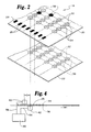
- the opposite side scanning mark sense form comprises a sheet of material having a timing track preprinted on only one side of the sheet and one or more response areas located on the opposite side of the sheet, or on both sides of the sheet, in a predetermined relationship to one of the timing marks in the timing track.
- the timing track consists of a plurality of preprinted timing marks typically arranged in a control column oriented along an edge of the sheet parallel to the direction in which the form travels through the optical mark reader.
- Each response area may include an associated response bubble printed as an outline for the user to selectively mark data marks on the mark sense form.
- the opposite side scanning optical mark reader comprises a first scanning means for scanning the timing track and response areas on one side of the form, a second scanning means for scanning response areas on the other side of the form and means for producing an enabling signal from the timing track on the one side of the form such that the second scanning means scans the response areas on the other side of the form in response to the enabling signal.
- the means for producing the enabling signal may be implemented using hardware, software, or a combination of both hardware and software.
- a microprocessor executing a software routine could be operably connected to the first and second scanning means to produce the enabling signal for the second scanning means in response to the scanning of the timing track by the first scanning means.
- a first scanning means scans the timing track and produces an enabling signal in response to the timing track on the form and a second and third scanning means scan the response areas on the respective sides of the form in response to the enabling signal from the first scanning means.
- a first scanning means scans the timing track and response areas on one side of the form and a second scanning means scans the timing track again to produce an enabling signal that is then used by a third scanning means for scanning the response areas on the other side of the form.
- the second scanning means is spaced apart from the first scanning means by a predetermined interval so that the first and third scanning means do not overlap scanning of both sides of the form. This stagger between scanning of the two sides of the form is necessary to prevent false reads or missed response bubbles because of light transmitted through the form that may cause improper scanning by the scanning means on the other side of the form.
- a primary objective of the present invention is to provide a method, apparatus and system for opposite side scanning of a mark sense form that does not require a timing track to be printed on the same side of the form as the response areas to be scanned.
- Another objective of the present invention is to provide a method, apparatus and system for opposite side scanning of a mark sense form that does not require a timing track to be printed on both sides of a dual sided mark sense form.
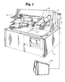
- an OpScan@ 21 optical mark scanner is modified in accordance with the present invention.
- the OpScan@ 21 optical mark scanner utilizes a pair of microprocessor boards 100 and 102 to control the operation of the first scanning means 40 and second scanning means 42, respectively, and an IBM/AT compatible microcomputer 110 as the processing means 46.
- the microprocessor boards 100 and 102 are connected via fiber optic communications links 120 and 122, respectively, to the microcomputer 110.
- the microcomputer 110 is equipped with a network optical transmitter (NOT) board 112 for handling communications over the fiber optic communications links 120 and 122.
- NOT network optical transmitter
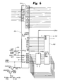
- the Cell/Gain Select Table combines both cell addressing and the gain correction in one byte of the table, so that the proper bits for cell selection and gain correction can be made available to the multiplexer logic at the same instant.
- Port 47 on the Super8 microprocessor 150 for the slave side board, microprocessor board 102, is programmed to receive the opposite side enabling signal.
- the control program for the slave side board includes additional control logic to enable the Super8 microprocessor to generate the necessary GRP SEL-N signals in response to the opposite side enabling signal 54.
- the control program may be provided with a delay compensation routine to adjust for the offset in response areas between first side 20 and second side 22 of the form 14.
- the delay compensation routine can also be used to adjust for timing delays in providing the opposite side enabling signal 54 to the slave side processor. Both positive and negative adjustments to the opposite side enabling signal are possible.
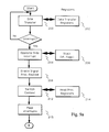
- Jump to Head Processing Routine 2108 control is now transferred into the standard head processing routine just after the point at which the Head Processing Routine 219 would have made the context switch to the Head Processing Register Group 214.
- Return Context 220 causes the register groups to be switched back to the Data Transfer Register Group 202.
- End Interrupt 222 an end- of-interrupt signal causes the Super8 microprocessor to restore the Instruction Pointer and CPU flags of the Super8 microprocessor from the stack to the values they had before the interrupt, so that the Data Transfer 200, or whatever process was running before, will be resumed just where it left off.
- the implementation of the software program for the master side microprocessor board may be accomplished by outputting the opposite side enabling signal 54 to Port 47 at the earliest possible point in the Head Processing Routine 219 of the master side board when a valid timing mark 26 is detected. It will also be recognized that the timing of the Head Processing Routine 219 for the master side board may need to be adjusted to accommodate the additional clock cycles necessary to output the opposite side enabling signal 54 to Port 47, something which could be accomplished by code revision or by slightly increasing the clock speed of the master side microprocessor board.
- a single control scanning means 72 separate from both the first scanning means 40 and the second scanning means 42 is used to generate the scanning control information 56 from the timing track 24.
- the scanning control information 56 is delayed for both the first scanning means 40 and the second scanning means 42 in accordance with the physical arrangement and separation of each of the scanning means.
Landscapes
- Engineering & Computer Science (AREA)
- Physics & Mathematics (AREA)
- General Physics & Mathematics (AREA)
- Theoretical Computer Science (AREA)
- Artificial Intelligence (AREA)
- Computer Vision & Pattern Recognition (AREA)
- Electromagnetism (AREA)
- Health & Medical Sciences (AREA)
- General Health & Medical Sciences (AREA)
- Toxicology (AREA)
- Facsimile Scanning Arrangements (AREA)
Applications Claiming Priority (2)
| Application Number | Priority Date | Filing Date | Title |
|---|---|---|---|
| US73885691A | 1991-07-31 | 1991-07-31 | |
| US738856 | 1991-07-31 |
Publications (2)
| Publication Number | Publication Date |
|---|---|
| EP0525806A2 true EP0525806A2 (fr) | 1993-02-03 |
| EP0525806A3 EP0525806A3 (en) | 1993-04-07 |
Family
ID=24969782
Family Applications (1)
| Application Number | Title | Priority Date | Filing Date |
|---|---|---|---|
| EP19920113124 Withdrawn EP0525806A3 (en) | 1991-07-31 | 1992-07-31 | Opposite side scanning of a mark sense form |
Country Status (2)
| Country | Link |
|---|---|
| EP (1) | EP0525806A3 (fr) |
| CA (1) | CA2074562A1 (fr) |
Cited By (2)
| Publication number | Priority date | Publication date | Assignee | Title |
|---|---|---|---|---|
| KR20010008717A (ko) * | 1999-07-02 | 2001-02-05 | 윤학범 | 광학식 카드 판독기 |
| WO2007024543A3 (fr) * | 2005-08-19 | 2008-04-10 | Global Payment Tech Inc | Lecteurs d'informations, appareils contenant ces lecteurs d'informations, et procedes correspondants |
Family Cites Families (2)
| Publication number | Priority date | Publication date | Assignee | Title |
|---|---|---|---|---|
| US3983364A (en) * | 1972-07-03 | 1976-09-28 | National Computer Systems, Inc. | Apparatus utilizing analog-to-digital conversion in the photoelectric reading of documents |
| US4479194A (en) * | 1982-08-10 | 1984-10-23 | Computer Election Systems | System and method for reading marks on a document |
-
1992
- 1992-07-23 CA CA 2074562 patent/CA2074562A1/fr not_active Abandoned
- 1992-07-31 EP EP19920113124 patent/EP0525806A3/en not_active Withdrawn
Cited By (3)
| Publication number | Priority date | Publication date | Assignee | Title |
|---|---|---|---|---|
| KR20010008717A (ko) * | 1999-07-02 | 2001-02-05 | 윤학범 | 광학식 카드 판독기 |
| WO2007024543A3 (fr) * | 2005-08-19 | 2008-04-10 | Global Payment Tech Inc | Lecteurs d'informations, appareils contenant ces lecteurs d'informations, et procedes correspondants |
| US7757951B2 (en) | 2005-08-19 | 2010-07-20 | Global Payment Technologies, Inc. | Information readers, apparatuses including information readers, and related methods |
Also Published As
| Publication number | Publication date |
|---|---|
| EP0525806A3 (en) | 1993-04-07 |
| CA2074562A1 (fr) | 1993-02-01 |
Similar Documents
| Publication | Publication Date | Title |
|---|---|---|
| US5488458A (en) | Duplex printing integrity system | |
| EP0103788B1 (fr) | Méthode et appareil pour lire des feuilles marquées | |
| US4661001A (en) | Label printer with test pattern for price and bar codes | |
| US5262624A (en) | Opposite surface scanning of a mark sense form | |
| JPH0210479A (ja) | データ処理フォームおよび安全装置の形成方法 | |
| JPS647274A (en) | Character reader | |
| EP0894624B2 (fr) | Dispositif d'identification d'une plaque d'impression ou d'un produit imprimé | |
| US4279002A (en) | Adapter for raster output scanning printer | |
| US4283622A (en) | Bar code reader | |
| JPH03218589A (ja) | ファクシミリを利用したコンピュータ入力システム | |
| EP0525806A2 (fr) | Balayage du verso d'un formulaire à perceptible perantible | |
| US3309669A (en) | Scanning apparatus for reading documents comprising a rotating scanning disc | |
| US3729618A (en) | Scanning mechanism and printer | |
| US5984189A (en) | Sheet for data codes and method of recognizing these codes | |
| US3502850A (en) | Data sensing system for a document scanner | |
| JPS62227757A (ja) | シリアルプリンタの印字位置ずれ補正装置 | |
| JPH011564A (ja) | 手動走査型記録装置 | |
| US3706887A (en) | Optical card reader | |
| US4182482A (en) | Method and mechanism for code sensing | |
| JPS605657Y2 (ja) | 原稿検出装置 | |
| JPS6320576A (ja) | 媒体認識装置 | |
| JP2815019B2 (ja) | 文字・マークの検出装置 | |
| JPS62198963A (ja) | 画像格納検索装置 | |
| JP2568712Y2 (ja) | タイムレコーダにおける識別コード読取装置 | |
| JPH07319996A (ja) | 光学文字読取装置 |
Legal Events
| Date | Code | Title | Description |
|---|---|---|---|
| PUAI | Public reference made under article 153(3) epc to a published international application that has entered the european phase |
Free format text: ORIGINAL CODE: 0009012 |
|
| AK | Designated contracting states |
Kind code of ref document: A2 Designated state(s): DE FR GB IT |
|
| PUAL | Search report despatched |
Free format text: ORIGINAL CODE: 0009013 |
|
| AK | Designated contracting states |
Kind code of ref document: A3 Designated state(s): DE FR GB IT |
|
| 17P | Request for examination filed |
Effective date: 19930714 |
|
| 17Q | First examination report despatched |
Effective date: 19940622 |
|
| STAA | Information on the status of an ep patent application or granted ep patent |
Free format text: STATUS: THE APPLICATION IS DEEMED TO BE WITHDRAWN |
|
| 18D | Application deemed to be withdrawn |
Effective date: 19950520 |