EP0525834A2 - Druckbehälter für einen Schalter - Google Patents
Druckbehälter für einen Schalter Download PDFInfo
- Publication number
- EP0525834A2 EP0525834A2 EP92118094A EP92118094A EP0525834A2 EP 0525834 A2 EP0525834 A2 EP 0525834A2 EP 92118094 A EP92118094 A EP 92118094A EP 92118094 A EP92118094 A EP 92118094A EP 0525834 A2 EP0525834 A2 EP 0525834A2
- Authority
- EP
- European Patent Office
- Prior art keywords
- insulative tube
- switch
- contact
- insulative
- pressure vessel
- Prior art date
- Legal status (The legal status is an assumption and is not a legal conclusion. Google has not performed a legal analysis and makes no representation as to the accuracy of the status listed.)
- Granted
Links
Images


Classifications
-
- H—ELECTRICITY
- H01—ELECTRIC ELEMENTS
- H01H—ELECTRIC SWITCHES; RELAYS; SELECTORS; EMERGENCY PROTECTIVE DEVICES
- H01H33/00—High-tension or heavy-current switches with arc-extinguishing or arc-preventing means
- H01H33/70—Switches with separate means for directing, obtaining, or increasing flow of arc-extinguishing fluid
- H01H33/88—Switches with separate means for directing, obtaining, or increasing flow of arc-extinguishing fluid the flow of arc-extinguishing fluid being produced or increased by movement of pistons or other pressure-producing parts
- H01H33/90—Switches with separate means for directing, obtaining, or increasing flow of arc-extinguishing fluid the flow of arc-extinguishing fluid being produced or increased by movement of pistons or other pressure-producing parts this movement being effected by or in conjunction with the contact-operating mechanism
- H01H33/91—Switches with separate means for directing, obtaining, or increasing flow of arc-extinguishing fluid the flow of arc-extinguishing fluid being produced or increased by movement of pistons or other pressure-producing parts this movement being effected by or in conjunction with the contact-operating mechanism the arc-extinguishing fluid being air or gas
-
- H—ELECTRICITY
- H01—ELECTRIC ELEMENTS
- H01H—ELECTRIC SWITCHES; RELAYS; SELECTORS; EMERGENCY PROTECTIVE DEVICES
- H01H33/00—High-tension or heavy-current switches with arc-extinguishing or arc-preventing means
- H01H33/02—Details
- H01H33/53—Cases; Reservoirs, tanks, piping or valves, for arc-extinguishing fluid; Accessories therefor, e.g. safety arrangements, pressure relief devices
- H01H33/56—Gas reservoirs
-
- H—ELECTRICITY
- H01—ELECTRIC ELEMENTS
- H01H—ELECTRIC SWITCHES; RELAYS; SELECTORS; EMERGENCY PROTECTIVE DEVICES
- H01H33/00—High-tension or heavy-current switches with arc-extinguishing or arc-preventing means
- H01H33/02—Details
- H01H33/025—Terminal arrangements
Definitions
- the present invention relates to a pressure vessel for a switch, and especially relates to an improvement of a pressure vessel for a puffer-type gas switch for opening and closing an electric circuit and is a divisional application from EP-A-0 311 017.
- FIG. 5 is a cross-sectional view showing a conventional puffer-type gas switch in an opening state of the contacts thereof.
- a lower tank 101 is fixed on a bottom flange 102.
- the lower tank 101 generally contains driving shafts (not shown) of three-phases which are connected to an operation mechanism and levers which connect the driving shafts and insulative rods 105 of the respective three-phases.
- the driving shafts, levers and operation mechanism are not shown for simplicity.
- An insulative tube 103 contains elements 104 for arc-extinction and is filled with insulation gas such as SF 6 .
- the insulative tube 103 has a double casing consisting of an inner arc-proof material 103a and an outer normal material 103b.
- An end of an insulative rod 105 which is connected to the driving lever (not shown in the figure) in the lower tank 101, is connected to an end of a conductive piston rod 106 which is reciprocatively driven in directions shown by arrows A and B.
- a disc-shaped piston 107 and a moving contact 108 are fixed.
- the piston 107 closely slides on an inner surface 103C of the insulative tube 103, and thereby the piston 107 compresses and expands the insulation gas in a lower space 109 and an upper space 110.
- An insulative nozzle 111 is fixed on the piston 107 co-axially with the moving contact 108 by a nozzle joiner 112.
- a fixed contact 113 to be connected to the moving contact 108 is fixed on an upper cover 115.
- electric current is capable of flowing when the moving contact 108 and the fixed contact 113 contact each other, and the actural path of electric current is from the sliding contact 114 to the piston rod 106.
- the pressure vessel of the above-mentioned conventional switch is filled by an insulation gas normally having pressure of 2-5 kg/cm 2.
- the pressure of the insulation gas builds up 10-20 kg/cm 2 when the electric current is cut off. Therefore, the thickness of the insulative tube 103 must be sufficiently thick for withstanding such a high pressure.
- the insulative tube 103 is made as a double casing and the inner part 103a is made of an arc-proof insulative material, it is difficult to make the thickness of the insulative tube 103 thin because mechanical strength of the insulatlve material against pressure becomes relatively weak.
- An object of the present invention is to provide an improved pressure vessel for a switch for overcoming the above problem.
- a pressure vessel for a switch in accordance with the present invention comprises:
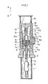
- FIG. 1 is a cross-sectional view showing the switch mechanism and the pressure vessel under a condition that the contacts are opened
- FIG. 2 is a cross-sectional view showing the switch mechanism and the pressure vessel shown in FIG. 1 under a condition that the contacts are closed
- FIG. 3 is an enlarged cross-sectional view showing details of FIG.2.
- a lower tank 1 is fixed on a bottom flange 2 and contains driving shafts of each three phases driven by an operation meehanism and insulative rods which are connected to the driving shafts.
- driving shafts and the operation mechanism are known in the art, they are not shown in the figure for simplifying the drawings.
- insulative rod 5 is shown in the figure.
- An insulative tube 3 contains arc-extinction elements 4 and is filled with insulation gas such as SF 6 .
- the arc-extinction elements 4 consist of, for example, an insulation rod 5, a conductive piston rod 6, a cylindrical piston 7 and a moving arc-contact 8.
- the insulative rod 5 is not connected to the driving lever.
- the conductive piston rod 6 is reciprocatively driven in directions shown by arrows A and B and is connected to an end of the insulative rod 5.
- the cylindrical piston 7 and a moving arc-contact 8 are fixed to the other end of the piston rod 6.
- the insulative tube 3 is molded with a tubular conductor 15.
- the piston 7 and a sliding contact 14 which is co-axially provided on the outer surface of the piston 7 slide on an inner surface 15a of the tubular conductor 15.
- the insulation gas in a lower space 9 and an upper space 10 is expanded and compressed by the motion of the piston 7.
- An insulative nozzle 11 is fixed on the piston 7 co-axially with the moving arc-contact 8 by a nozzle joiner 12.
- a fixed contaet 13 to be connected to the moving arc-contact 8 and having a tubular shape is fixed on an upper terminal 18.
- the current collectors 16 serve as a main moving contact.
- a lower terminal 17 is electrically in contact with the tubular conductor 15 and is provided at a midway position of the insulative tube 3.
- An upper tank 19 is fixed on the upper terminal 18 and thereby the insulation gas is sealed in the insulative tube 3.
- two compression springs 30 and 31 are provided between an inner surface 7a of the piston 7 and an outer surface 16a of each current collector 16 so as to apply contact pressures at positions C and D.
- the current collector 16 departs the fixed contact 13 according as movement of the movable element of the arc-extinction elements 4 in the direction shown by arrow B.
- an arc is discharged.
- the pressure of the insulation gas in the lower space 9 becomes higher than those of the gases in other spaces.
- pressure buildup due to the arc discharge is above about zero point of the current, the insulation gas in the bottom space 9, where the pressure of the insulation gases is high, flows to other space where the pressures are lower than that in the bottom space 9.
- gas passing through a hole 7b of the piston 7 flows through a hole 11 a of the nozzle 11 and a hole 13c of the fixed contact 13 to the upper space 10 and the upper tank 19, and another gas passing through a gap 6a between the insulative tube 3 and the piston rod 6 flows to an inner space 1 a of the bottom tank 1.
- the insulation gas flowing from the bottom space 9 to the upper space 10 collides with an arc made by discharge between the fixed contact 13 and the moving arc-contact 8. Accordingly, the arc is cooled and diffused by the flow of the insulation gas, and finally the arc is extinguished. When the arc is extinguished, the switching off of the circuit is completed.
- the movable elements of the arc-distinction elements 4 moves in a reverse direction shown by arrow A, and the switch is closed by contact of the current collectors 16 (which serve as a main moving contact) and the fixed contact 13.
- the insulation gas is sealed in the insulative tube 3 in a pressure of about 2-5 kg/cm 2. Therefore, a stress 6, in radial direction and a stress 6,5 in circumferential direction corresponding to the pressure of the insulation gas always act onto the insulative tube 3.
- the insulative tube 3 having the inner tubular conductor 15 is manufactured by a cast molding process in a temperature range of 150-200 C. When the insulative tube 3 is cooled to the normal temperature from the above-mentioned high temperature range, the insulative tube 3 is hardened and contracts, and the tubular conductor 15 also contracts in proportion to the temperature difference.
- the stress ⁇ ⁇ in circumferential direction of the insulative tube 3 is always in compressing state (since the stress ⁇ ⁇ in circumferential direction is generally larger than the stress sy in radial direction).
- the tubular conductor 15 receives abnormal high pressure of the insulation gas which may occur at accidental over-current breaking. Namely, the tubular conductor 15 serves as a reinforcement of the insulative tube 3 for partially charging the internal stress of the insulative tube 3. As a result, the thickness of the side wall of the insulative tube 3 can be made thin.
- FIG. 4 Another preferred embodiment of the pressure vessel in accordance with the present invention is described in reference to FIG. 4.
- a second tubular conductor 22 is provided co-axially with the outer surface of the tubular conductor 15.
- the second tubular conductor 22 is fixed to the tubular conductor 15 with electric conductivity thereto.
- a conductive material having a larger thermal expansion coefficient than that of the material of the insulative tube 3, and smaller than that of the conductive material of the tubular conductor 15 is suitable.
- absolute values of the difference of the stresses acting to the insulative tube 3 and the second tubular conductor 22 or acting to the second tubular conductor 22 and the tubular conductor 15 can be reduced. Accordingly, pull-out type fracture occurring at a boundary between the insulative tube 3 and the second tubular conductor 22 can be prevented.
- the insulative tube 3 for containing the switch mechanism and the arc-extinction elements of a switch can be utilized for any types of pressure vessels made of resin.
- the tubular conductor 15 is provided on a peripheral part of the lower space 9 where the pressure of the insulation gas will be the highest.
- the pressure of the insulation gas surrounding the arc-discharging part between the moving arc-contact 8 and the fixed contact 13 becomes the highest. Therefore, a constitution similar to the above-mentioned can be adopted thereto.
- the insulative tube 3 is molded with the inserted tubular conductor 15.
- the tubular conductor 15, however, is not necessarily conductive when a method for collecting electric current similar to the prior art for correcting the electric current from the midway portion of the piston rod 6 is adopted.
Landscapes
- Circuit Breakers (AREA)
- Gas-Insulated Switchgears (AREA)
- Driving Mechanisms And Operating Circuits Of Arc-Extinguishing High-Tension Switches (AREA)
Applications Claiming Priority (7)
| Application Number | Priority Date | Filing Date | Title |
|---|---|---|---|
| JP251932/87 | 1987-10-05 | ||
| JP251931/87 | 1987-10-05 | ||
| JP251942/87 | 1987-10-05 | ||
| JP62251942A JPH0195428A (ja) | 1987-10-05 | 1987-10-05 | 開閉器の消弧装置 |
| JP62251932A JP2666933B2 (ja) | 1987-10-05 | 1987-10-05 | 開閉器の消弧装置 |
| JP62251931A JP2585632B2 (ja) | 1987-10-05 | 1987-10-05 | 開閉器の圧力容器 |
| EP88116406A EP0311017B2 (de) | 1987-10-05 | 1988-10-04 | Lichtbogenlöscheinrichtung für Schalter |
Related Parent Applications (2)
| Application Number | Title | Priority Date | Filing Date |
|---|---|---|---|
| EP88116406.5 Division | 1988-10-04 | ||
| EP88116406A Division EP0311017B2 (de) | 1987-10-05 | 1988-10-04 | Lichtbogenlöscheinrichtung für Schalter |
Publications (3)
| Publication Number | Publication Date |
|---|---|
| EP0525834A2 true EP0525834A2 (de) | 1993-02-03 |
| EP0525834A3 EP0525834A3 (de) | 1993-02-24 |
| EP0525834B1 EP0525834B1 (de) | 1995-08-30 |
Family
ID=27334073
Family Applications (2)
| Application Number | Title | Priority Date | Filing Date |
|---|---|---|---|
| EP92118094A Expired - Lifetime EP0525834B1 (de) | 1987-10-05 | 1988-10-04 | Druckbehälter für einen Schalter |
| EP88116406A Expired - Lifetime EP0311017B2 (de) | 1987-10-05 | 1988-10-04 | Lichtbogenlöscheinrichtung für Schalter |
Family Applications After (1)
| Application Number | Title | Priority Date | Filing Date |
|---|---|---|---|
| EP88116406A Expired - Lifetime EP0311017B2 (de) | 1987-10-05 | 1988-10-04 | Lichtbogenlöscheinrichtung für Schalter |
Country Status (4)
| Country | Link |
|---|---|
| US (1) | US5077453A (de) |
| EP (2) | EP0525834B1 (de) |
| KR (1) | KR910003436B1 (de) |
| DE (2) | DE3887245T3 (de) |
Families Citing this family (3)
| Publication number | Priority date | Publication date | Assignee | Title |
|---|---|---|---|---|
| KR100722479B1 (ko) * | 2005-12-30 | 2007-05-28 | 엘에스산전 주식회사 | 진공차단기 |
| CN102024626A (zh) * | 2010-12-16 | 2011-04-20 | 中国振华集团群英无线电器材厂 | 电磁开关 |
| JP6017105B1 (ja) * | 2016-01-19 | 2016-10-26 | 三菱電機株式会社 | ガス遮断器 |
Family Cites Families (17)
| Publication number | Priority date | Publication date | Assignee | Title |
|---|---|---|---|---|
| FR1145609A (fr) * | 1956-03-10 | 1957-10-28 | Comp Generale Electricite | Dispositif à contacts glissants électriques |
| FR1371514A (fr) * | 1962-10-03 | 1964-09-04 | Bbc Brown Boveri & Cie | Accouplement électrique formé de deux têtes d'accouplement |
| FR2266285A1 (en) * | 1974-03-27 | 1975-10-24 | Cem Comp Electro Mec | Insulating gas contg. cct. breaker - has polyphase insulating casing with embedded current lead bolts coupled to casing metal lining |
| US4041263A (en) * | 1975-08-22 | 1977-08-09 | General Electric Company | Electric circuit interrupter of the puffer type comprising a magnetically actuated piston |
| DE2658235A1 (de) † | 1976-12-22 | 1978-07-06 | Siemens Ag | Verfahren und vorrichtung zur loeschung eines lichtbogens in einem gasstroemungsschalter |
| US4268733A (en) * | 1977-10-19 | 1981-05-19 | Gould Inc. | Liquid SF6 puffer type circuit interrupter |
| DE2809509A1 (de) * | 1978-03-06 | 1979-09-13 | Licentia Gmbh | Druckgas-leistungsschalter |
| CH625908A5 (de) † | 1978-03-30 | 1981-10-15 | Sprecher & Schuh Ag | |
| JPS5517924A (en) * | 1978-07-26 | 1980-02-07 | Hitachi Ltd | Buffer type gas breaker |
| JPS5548520A (en) * | 1978-10-03 | 1980-04-07 | Shibaura Eng Works Co Ltd | Cutter |
| CH648153A5 (de) † | 1979-04-24 | 1985-02-28 | Sprecher & Schuh Ag | Druckgasschalter. |
| SE417032B (sv) † | 1979-05-18 | 1981-02-16 | Asea Ab | Elektrisk brytare med gasformigt sleckmedel |
| CH655611B (de) † | 1981-06-18 | 1986-04-30 | ||
| EP0081253A1 (de) † | 1981-12-03 | 1983-06-15 | BBC Aktiengesellschaft Brown, Boveri & Cie. | Druckgasschalter |
| US4445018A (en) * | 1982-01-07 | 1984-04-24 | Mcgraw-Edison Company | Energy efficient floating head puffer interrupter |
| US4459447A (en) * | 1982-01-27 | 1984-07-10 | Mitsubishi Denki Kabushiki Kaisha | Self extinguishing type gas circuit breaker |
| CH669864A5 (de) * | 1986-03-27 | 1989-04-14 | Bbc Brown Boveri & Cie |
-
1988
- 1988-07-25 KR KR1019880009315A patent/KR910003436B1/ko not_active Expired
- 1988-10-04 EP EP92118094A patent/EP0525834B1/de not_active Expired - Lifetime
- 1988-10-04 DE DE3887245T patent/DE3887245T3/de not_active Expired - Fee Related
- 1988-10-04 DE DE3854402T patent/DE3854402T2/de not_active Expired - Fee Related
- 1988-10-04 EP EP88116406A patent/EP0311017B2/de not_active Expired - Lifetime
-
1990
- 1990-11-16 US US07/614,027 patent/US5077453A/en not_active Expired - Fee Related
Also Published As
| Publication number | Publication date |
|---|---|
| DE3854402T2 (de) | 1996-02-29 |
| KR890007339A (ko) | 1989-06-19 |
| DE3887245T2 (de) | 1994-05-05 |
| KR910003436B1 (ko) | 1991-05-31 |
| EP0311017B2 (de) | 1998-09-16 |
| DE3854402D1 (de) | 1995-10-05 |
| DE3887245T3 (de) | 1999-01-21 |
| US5077453A (en) | 1991-12-31 |
| EP0311017B1 (de) | 1994-01-19 |
| EP0311017A2 (de) | 1989-04-12 |
| EP0525834B1 (de) | 1995-08-30 |
| EP0311017A3 (en) | 1990-07-04 |
| DE3887245D1 (de) | 1994-03-03 |
| EP0525834A3 (de) | 1993-02-24 |
Similar Documents
| Publication | Publication Date | Title |
|---|---|---|
| EP2761639B1 (de) | Vakuumschaltvorrichtung mit einer ersten und einer zweiten beweglichen kontaktanordnung sowie elektrische vakuumschaltvorrichtung damit | |
| US5905242A (en) | High voltage hybrid circuit-breaker | |
| US20100000972A1 (en) | Vacuum Circuit Breaker | |
| EP2593953B1 (de) | Verfahren zur herstellung eines polteils für einen schutzschalter | |
| US3813506A (en) | Vacuum-type circuit breaker with improved ability to interrupt capacitance currents | |
| EP0745262B1 (de) | Hochleistungsschalter mit bedienungsgestaenge und konische durchfuehrung | |
| EP1615309B1 (de) | Schaltvorrichtung | |
| JPH0664975B2 (ja) | 圧縮ガスしや断器 | |
| US20030178392A1 (en) | Switching mechanism of circuit breaker for gas insulted switchgear | |
| US4617435A (en) | Hybrid circuit breaker | |
| US6365863B1 (en) | High voltage circuit-breaker with a counter-contact which can be actuated | |
| EP0088442B1 (de) | Autopneumatischer Druckgasschalter | |
| EP0525834B1 (de) | Druckbehälter für einen Schalter | |
| JP2005108766A (ja) | 2点切り真空遮断器 | |
| CA1211487A (en) | High-voltage y-shaped dead tank circuit interrupter | |
| KR100972266B1 (ko) | 진공 스위치 기어 | |
| CA1040689A (en) | Motion-multiplying linkage-mechanism for sealed-casing structures | |
| CA2009289A1 (en) | Metal-clad, compressed gas-blast circuit-breaker with a shifting linkage | |
| WO2005059938A1 (en) | Nozzle for a gas-insulated switching device and related switching device | |
| US3238344A (en) | Externally controlled hermetically enclosed electric switch | |
| US4480161A (en) | Circuit breaker utilizing improved arc chambers | |
| US11621131B2 (en) | Switching device with improved epoxy hermetic seal | |
| CA1178315A (en) | Puffer type current interrupter | |
| KR950011296B1 (ko) | 고절연 내력을 갖는 퍼훠형 전기회로 차단기 | |
| JP2585632B2 (ja) | 開閉器の圧力容器 |
Legal Events
| Date | Code | Title | Description |
|---|---|---|---|
| PUAI | Public reference made under article 153(3) epc to a published international application that has entered the european phase |
Free format text: ORIGINAL CODE: 0009012 |
|
| PUAL | Search report despatched |
Free format text: ORIGINAL CODE: 0009013 |
|
| AC | Divisional application: reference to earlier application |
Ref document number: 311017 Country of ref document: EP |
|
| AK | Designated contracting states |
Kind code of ref document: A2 Designated state(s): CH DE FR LI |
|
| AK | Designated contracting states |
Kind code of ref document: A3 Designated state(s): CH DE FR LI |
|
| 17P | Request for examination filed |
Effective date: 19930601 |
|
| 17Q | First examination report despatched |
Effective date: 19930921 |
|
| GRAA | (expected) grant |
Free format text: ORIGINAL CODE: 0009210 |
|
| AC | Divisional application: reference to earlier application |
Ref document number: 311017 Country of ref document: EP |
|
| AK | Designated contracting states |
Kind code of ref document: B1 Designated state(s): CH DE FR LI |
|
| REF | Corresponds to: |
Ref document number: 3854402 Country of ref document: DE Date of ref document: 19951005 |
|
| ET | Fr: translation filed | ||
| PLBE | No opposition filed within time limit |
Free format text: ORIGINAL CODE: 0009261 |
|
| STAA | Information on the status of an ep patent application or granted ep patent |
Free format text: STATUS: NO OPPOSITION FILED WITHIN TIME LIMIT |
|
| 26N | No opposition filed | ||
| REG | Reference to a national code |
Ref country code: FR Ref legal event code: D6 |
|
| PGFP | Annual fee paid to national office [announced via postgrant information from national office to epo] |
Ref country code: FR Payment date: 19981009 Year of fee payment: 11 |
|
| PGFP | Annual fee paid to national office [announced via postgrant information from national office to epo] |
Ref country code: DE Payment date: 19981012 Year of fee payment: 11 |
|
| PGFP | Annual fee paid to national office [announced via postgrant information from national office to epo] |
Ref country code: CH Payment date: 19981022 Year of fee payment: 11 |
|
| PG25 | Lapsed in a contracting state [announced via postgrant information from national office to epo] |
Ref country code: LI Free format text: LAPSE BECAUSE OF NON-PAYMENT OF DUE FEES Effective date: 19991031 Ref country code: CH Free format text: LAPSE BECAUSE OF NON-PAYMENT OF DUE FEES Effective date: 19991031 |
|
| REG | Reference to a national code |
Ref country code: CH Ref legal event code: PL |
|
| PG25 | Lapsed in a contracting state [announced via postgrant information from national office to epo] |
Ref country code: FR Free format text: LAPSE BECAUSE OF NON-PAYMENT OF DUE FEES Effective date: 20000630 |
|
| PG25 | Lapsed in a contracting state [announced via postgrant information from national office to epo] |
Ref country code: DE Free format text: LAPSE BECAUSE OF NON-PAYMENT OF DUE FEES Effective date: 20000801 |
|
| REG | Reference to a national code |
Ref country code: FR Ref legal event code: ST |