EP0525837A2 - Dispositif pour tendre une ceinture de sécurité dans un véhicule, en particulier véhicule automobile - Google Patents
Dispositif pour tendre une ceinture de sécurité dans un véhicule, en particulier véhicule automobile Download PDFInfo
- Publication number
- EP0525837A2 EP0525837A2 EP92118210A EP92118210A EP0525837A2 EP 0525837 A2 EP0525837 A2 EP 0525837A2 EP 92118210 A EP92118210 A EP 92118210A EP 92118210 A EP92118210 A EP 92118210A EP 0525837 A2 EP0525837 A2 EP 0525837A2
- Authority
- EP
- European Patent Office
- Prior art keywords
- housing
- movement
- bowden cable
- cable
- compression spring
- Prior art date
- Legal status (The legal status is an assumption and is not a legal conclusion. Google has not performed a legal analysis and makes no representation as to the accuracy of the status listed.)
- Granted
Links
- 230000006835 compression Effects 0.000 claims abstract description 42
- 238000007906 compression Methods 0.000 claims abstract description 42
- 230000001404 mediated effect Effects 0.000 claims description 4
- 230000000903 blocking effect Effects 0.000 claims description 2
- 230000005540 biological transmission Effects 0.000 claims 1
- 210000002445 nipple Anatomy 0.000 description 3
- 230000001960 triggered effect Effects 0.000 description 2
- 239000011324 bead Substances 0.000 description 1
Images


Classifications
-
- B—PERFORMING OPERATIONS; TRANSPORTING
- B60—VEHICLES IN GENERAL
- B60R—VEHICLES, VEHICLE FITTINGS, OR VEHICLE PARTS, NOT OTHERWISE PROVIDED FOR
- B60R22/00—Safety belts or body harnesses in vehicles
- B60R22/18—Anchoring devices
- B60R22/195—Anchoring devices with means to tension the belt in an emergency, e.g. means of the through-anchor or splitted reel type
- B60R22/1952—Transmission of tensioning power by cable; Return motion locking means therefor
- B60R22/1953—Transmission of tensioning power by cable; Return motion locking means therefor the cable being pulled by mechanical means, e.g. pre-stressed springs, bumper displacement during crash
-
- A—HUMAN NECESSITIES
- A44—HABERDASHERY; JEWELLERY
- A44B—BUTTONS, PINS, BUCKLES, SLIDE FASTENERS, OR THE LIKE
- A44B11/00—Buckles; Similar fasteners for interconnecting straps or the like, e.g. for safety belts
- A44B11/25—Buckles; Similar fasteners for interconnecting straps or the like, e.g. for safety belts with two or more separable parts
- A44B11/2503—Safety buckles
- A44B11/2507—Safety buckles actuated by a push-button
Definitions
- the invention relates to a device for tightening a seat belt in a vehicle, in particular a motor vehicle, with a sensor which responds to an extreme change in vehicle speed, a compression spring arranged in a housing, which, by means of a lock, locks an energy store held in a tensioned state for a belt tightening back tensioning movement forms a traction cable connected to the seat belt, to which the back tensioning movement is transmitted in the unlocked state of the energy accumulator, and a backstop which has a blocking effect in a direction of movement of the traction rope opposite to the back tensioning movement.
- the object of the invention is to provide such a device for tightening a seat belt in a vehicle, in particular a motor vehicle, in which an unintentional triggering of the sensor, in particular when adjusting the vehicle seat, is prevented.
- the senor and the pressure spring forming the energy accumulator are arranged in a first housing fixed to the vehicle, and the backstop is provided in a second housing which can be adjusted with a vehicle seat, and in that a Bowden cable is provided which back tension movement generated by the unlocked compression spring transmits from the compression spring to the backstop connected to the pull rope.
- the sensor and the compression spring forming the energy accumulator are mounted on the vehicle in a stationary manner in a first housing.
- the backstop for the traction cable is separated from it and can be adjusted with the vehicle seat in a second housing.
- the two housings can be arranged one behind the other so that the housing containing the senso and the compression spring is firmly connected to a stationary part, for example connected to the vehicle floor, in particular the lower anchor rail of the vehicle seat, and the second housing, which accommodates the backstop, with the upper anchor rail adjustable with the vehicle seat are connected.
- the sensor acts in one housing and then, when the compression spring is unlocked, its return movement on the traction cable and in the other housing after the tightening movement, the backstop on the traction cable.
- the Bowden cable sheath can be movably guided on the first housing in the direction of the back tensioning movement mediated by the compression spring, with one end of the Bowden cable wire being firmly connected to the first housing and the second end of the Bowden cable wire being connected to the cable.
- the movement of the Bowden cable cover with respect to the first housing is transferred to the end of the Bowden cable wire connected to the traction cable during the back tensioning movement of the compression spring, as a result of which the desired back tensioning movement for the seat belt is achieved.
- a further embodiment consists in that the back tightening movement of the unlocked compression spring is transmitted to one end of the Bowden cable wire and the other end of the Bowden cable wire is connected to the pull cable.
- the compression spring acting as an energy store can be supported at one end on a locking bolt which belongs to the locking mechanism and at the other end on a part connected to the Bowden cable wire.
- a sensor spring can be provided, which is designed as a compression spring and is supported at one end on the locking bolt and at the other end on a part connected to the Bowden cable wire. This ensures that the locking bolt maintains a defined position in the first housing, so that, in particular in the event of a crash, the two sensor parts can move away from one another so that the locking element can be pivoted out of its locking position by the force of the compression spring.
- the backstop provided in the second housing preferably acts on the pull rope.
- the pull cable can be connected to the Bowden cable wire in the second housing via a cable connecting piece which is guided axially in the second housing.
- the backstop can be designed as a locking ellipse, which in the rest position and tightening movement is guided in a defined inclined position without jamming in the second housing designed as a brake tube and can be brought into a clamped-locked position by tilting against an opposite direction of movement. This tilting into the clamp-locked position can be supported by a locking spring.
- the seat belt buckle of the seat belt can also be adjusted when the vehicle seat is adjusted in height, it is sufficient if that End of the second housing, from which the pull rope is guided to the seat belt, in particular to the hip point, is also pivoted during the height adjustment.
- the other end of the second housing can then be articulated on the adjustable vehicle seat, in particular on the upper displaceable anchor rail.
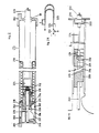
- the exemplary embodiments of the rear tensioner devices shown in the figures have two, in particular tubular, housings 1 and 231.
- a compression spring 22 is arranged in the first housing 1 and, in the tensioned idle state, forms the energy accumulator for the back tensioning movement which eliminates the strapless.
- the sensor device is arranged in the first housing 1, which essentially consist of locking levers 206 (three locking levers 206 are provided in FIG. 1), a round wire ring 207, with which the locking levers 206 are held on a locking bolt 208 in an indefinable pivotable position.
- the locking levers 206 each have sensor levers 217 on sensor surfaces 216 which are formed by shoulder-shaped projections of a support part 203 which is fastened to the housing.
- the first housing 1 is fixed in place on the vehicle, for example on a bottom part of the vehicle, with the aid of a housing holder 202.
- the compression spring 22 is supported at one end via an annular spring holder 211, a locking element 214 and a locking engagement part 215 on a locking bolt 208 opposite the supporting part 203, which is fastened to the housing 1.
- the other end of the compression spring 22 is supported on a support collar 239 of a guide tube 213, which is fastened to the locking bolt 208 by means of a round wire ring 209 and beads molded into the guide tube.
- the compression spring 22 is locked in such a way that the compression spring 22 exerts a compressive force on the locking element 214 on the locking lever 206 via the spring holder 211, by means of which the locking element 214 is pressed into the locking engagement part 215 on the locking bolt 208.
- the sensor arm 217 of the locking lever 206 rests on the sensor surface 216 on the support part 203.
- the locking lever 206 is held in a defined position relative to the locking bolt 208 by the round wire ring 207.
- the locking bolts 206 are in the region of the outer surface of the bolt engagement 215 pivotally mounted about a pivot axis 248 on the bolt bolt 208.
- the back tensioning movement which is mediated by the compression spring 22, is connected via a Bowden cable, which consists of a Bowden cable wire 224 and a Bowden cable wire 223 surrounding the Bowden cable wire 224, to a seat belt, not shown Transfer rope 241.
- a Bowden cable which consists of a Bowden cable wire 224 and a Bowden cable wire 223 surrounding the Bowden cable wire 224
- One end of the pull wire 224 is fixed on the housing 1, in particular on the support part 203, for example with the aid of a locking ring 205.
- This connection point is covered to the outside by a cover 204.
- the securing ring 205 is connected to a support bolt 225, which has a connecting piece 219 with which the pull wire 224 is pressed.
- the support bolt 225 and the widened connecting piece 219 are arranged coaxially in an inner bore of the locking bolt 208.
- the widened connecting piece 219 has a support shoulder on which the sensor spring 210 is supported at one end.
- the other end of the sensor spring 210 designed as a compression spring is supported on an inwardly projecting support collar 220 on the locking bolt 208.
- sensor spring 210 is designed as a conical spring. However, it can also be designed as a cylinder compression spring, as is shown, for example, in the exemplary embodiment in FIG. 3, wherein a support disk (not shown in more detail) can also be provided between the connecting piece 219 and the sensor spring 210.
- the Bowden cable casing 223 is supported against the locking bolt 208 via a support part 221.
- the support part 221 is inside the guide guiding tube 213 coaxially.
- the Bowden cable sheath 223 preferably lies loosely against the locking bolt 208.
- the Bowden cable, ie the pull wire 224 and the sheath 223 surrounding it, are guided coaxially within the first housing 1.
- the Bowden cable is held in the housing holder 202 with the aid of a clamping nipple 218.
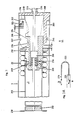
- the backstop is arranged in the second tubular housing 231.
- This tubular housing 231 acts as a brake tube for the backstop.
- the backstop essentially contains a locking ellipse 234 which interacts with the inside of the tube in the same way as that described in the main application.
- the locking ellipse 234 of the exemplary embodiment shown has lateral recesses 237, 238, in which the traction cable 241 engages.
- the other end of the pull wire 224 is also connected to the pull cable 241.
- the end of the pull wire is pressed with a conical nipple 226, which is inserted into a cable anchor 232 acting as a connecting piece.
- the end loop of the pull cable 241 is also inserted into this cable anchor 232.
- the end loop of the pull cable 241 also lies in the two recesses 237 and 238 of the locking ellipse 234 and in a cable guide piece 233. This ensures that the pull cable 241 and the pull wire 224 are guided axially within the housing 231.
- the locking ellipse 234 is guided in the rest position and in the back tightening direction (arrow A) in the defined inclined position shown in FIG. 2 without jamming.
- an oblique guide surface is provided on the guide part 233, through which the clamp-free oblique position of the locking ellipse 234 is defined.
- One leg of a securing spring 235 is located between the oblique guide surface on the rope guide part 203 and the locking ellipse 234. This securing spring 235 is approximately U-shaped and is supported with its other spring leg in the rope anchor 232.
- the locking spring 234 is pivoted in the direction of an arrow B after the back tightening movement has ended, so that the locking ellipse 234 tilts into a clamping locking position.
- the locking ellipse 234 is clamped in the housing interior 231, which then acts as a brake tube. A movement of the pull rope 241 against the back tension direction A is then no longer possible. The strapless is thus safely removed from the seat belt.
- the other end of the Bowden cable sleeve 223 is not supported and fixed on the second housing 231 with the aid of a support part 222 on one end of the tubular housing 231.
- FIG. 3 differs from the embodiment shown in FIGS. 1 and 2 in that the back tensioning movement mediated by the compression spring 22 is transmitted directly to the Bowden wire 224.
- the pulling cable can also be acted upon directly with the back-tensioning movement of the unlocked compression spring 22.
- the arrangement in the second housing 231, i. H. the backstop arrangement is the same as in the embodiment of Figures 1 and 2.
- the pull wire 224 of the Bowden cable is connected at its end to the guide tube 213.
- the pull wire 224 can be attached directly to the guide tube 213 at the pull wire attachment 240, or a pin can be attached in the pull wire attachment 240 and this pin can be connected to the pull wire 224 by a connecting piece 219.
- the connecting piece 219 is axially guided in an inner bore of the locking bolt 208.
- the sensor spring 210 which is designed as a compression spring, is inserted between the connecting piece 219, which is widened compared to the pull wire 224, and the support collar 220 on the locking bolt 208.
- the sensor spring 210 is designed as a cylindrical spring. However, it can be in the same way as in the embodiment of Figures 1 and 2 as a cone be designed spring.
- the compression spring 22 expands and causes a backward tightening movement in the direction of an arrow D.
- the pull wire 224 is moved within the Bowden cable sheath 223. This movement is also shown in FIG. 3A.
- the end of the pull wire 224 fixed on the guide tube 213 is moved in this direction.
- This back tightening movement is also transmitted to the other end of the pull wire 224, which is connected in the second housing 231 to the pull cable in the same way as in the exemplary embodiment in FIGS. 1 and 2.
- the required back pull movement is therefore transmitted to the pull cable in the direction of arrow A, which the strapless removed from the seat belt.
- the locking element 214 is pressed between the annular spring holder 211 and the locking engagement part 215 on the locking bolt 208.
- the locking element is provided in one piece on the locking lever 206 (also in the embodiment in FIG. 4, which represents an enlarged illustration for the embodiment of FIGS. 1 and 2). While in the embodiment of FIG. 4 the sensor arm 217, which is also provided on the locking lever 206, bears against the sensor surface 216, which is molded onto the support part 203, in the embodiment of FIG. 3 an engaging part 245 is provided on the housing 1, which engages on the Inner wall of the housing 1 is attached.
- This engagement part 245 has the sensor surface 216, on which the sensor lever 217 is in engagement with a sensor surface.
- a distance L is present between the engagement part 245 and the locking lever 206, which enables the sensor lever 217 to disengage from the sensor surface 216 on the engagement part in the event of a crash.
- a further distance Z is provided between the annular spring holder 3 and the support part 203.
- the locking bolt 208 is guided in the axial direction in a guide sleeve 246 which is molded onto the support part 203.
- This guide sleeve 246 has guide slots 247 in which the locking levers 206 are located.
- the compression spring 22 acting as an inertial mass moves to the right in FIGS. 1 and 3.
- the sensor surfaces 216 disengage from the sensor levers 217 and, due to the pressure force which the compression spring 22 exerts on the locking element 214 on the locking levers 206, the locking elements 214 move out of their locking position about a pivot axis 248, which in the support region of the locking lever 206 on the locking bolt 208 is pivoted so that they come out of engagement with the engaging part 215 on the locking bolt 208.
- the locking of the compression spring 22 is released and, as already explained, this can expand and produce the back tightening movement for the removal of the belt loops.
- the compression spring 22 is then supported on the support part 203 via the spring holder 211.
- a height adjustment of the seat can also be carried out by the second housing 231, which contains the backstop.
- the second housing 231 which contains the backstop.
- the corresponding end of the housing 231 is pivotally attached to a link lever 254, the link lever 254 being pivotally attached to the adjustable seat rail 251.
- the other end of the second housing 231 is articulated by means of a holder 252 on the adjustable seat rail 251.
Landscapes
- Engineering & Computer Science (AREA)
- Mechanical Engineering (AREA)
- Automotive Seat Belt Assembly (AREA)
- Bending Of Plates, Rods, And Pipes (AREA)
- Devices For Conveying Motion By Means Of Endless Flexible Members (AREA)
- Seats For Vehicles (AREA)
Applications Claiming Priority (9)
| Application Number | Priority Date | Filing Date | Title |
|---|---|---|---|
| DE3915723 | 1989-05-13 | ||
| DE3915723 | 1989-05-13 | ||
| DE3932090 | 1989-09-26 | ||
| DE19893932090 DE3932090A1 (de) | 1989-05-13 | 1989-09-26 | Vorrichtung zum straffen eines sicherheitsgurtes in einem fahrzeug, insbesondere kraftfahrzeug |
| DE19893933009 DE3933009A1 (de) | 1989-09-26 | 1989-10-03 | Vorrichtung zum straffen eines sicherheitsgurtes in einem fahrzeug, insbesondere kraftfahrzeug |
| DE3933009 | 1989-10-03 | ||
| DE19893933276 DE3933276A1 (de) | 1989-10-05 | 1989-10-05 | Rueckstrammvorrichtung fuer einen sicherheitsgurt eines fahrzeugsitzes |
| DE3933276 | 1989-10-05 | ||
| EP90106535A EP0398010B1 (fr) | 1989-05-13 | 1990-04-05 | Dispositif de blocage et dispositif pour tendre une ceinture de sécurité dans un véhicule, en particulier dans un véhicule automobile |
Related Parent Applications (2)
| Application Number | Title | Priority Date | Filing Date |
|---|---|---|---|
| EP90106535.9 Division | 1990-04-05 | ||
| EP90106535A Division EP0398010B1 (fr) | 1989-05-13 | 1990-04-05 | Dispositif de blocage et dispositif pour tendre une ceinture de sécurité dans un véhicule, en particulier dans un véhicule automobile |
Publications (3)
| Publication Number | Publication Date |
|---|---|
| EP0525837A2 true EP0525837A2 (fr) | 1993-02-03 |
| EP0525837A3 EP0525837A3 (en) | 1993-05-12 |
| EP0525837B1 EP0525837B1 (fr) | 1995-01-04 |
Family
ID=27434598
Family Applications (4)
| Application Number | Title | Priority Date | Filing Date |
|---|---|---|---|
| EP93115014A Expired - Lifetime EP0587191B1 (fr) | 1989-05-13 | 1990-04-05 | Tube de freinage d'un blocage antiretour d'un système de rattrapage de jeu pour ceinture de sécurité |
| EP92118210A Expired - Lifetime EP0525837B1 (fr) | 1989-05-13 | 1990-04-05 | Dispositif pour tendre une ceinture de sécurité dans un véhicule, en particulier véhicule automobile |
| EP94100531A Expired - Lifetime EP0599810B1 (fr) | 1989-05-13 | 1990-04-05 | Dispositif pour tendre une ceinture de sécurité dans un véhicule, en particulier dans un véhicule automobile |
| EP90106535A Expired - Lifetime EP0398010B1 (fr) | 1989-05-13 | 1990-04-05 | Dispositif de blocage et dispositif pour tendre une ceinture de sécurité dans un véhicule, en particulier dans un véhicule automobile |
Family Applications Before (1)
| Application Number | Title | Priority Date | Filing Date |
|---|---|---|---|
| EP93115014A Expired - Lifetime EP0587191B1 (fr) | 1989-05-13 | 1990-04-05 | Tube de freinage d'un blocage antiretour d'un système de rattrapage de jeu pour ceinture de sécurité |
Family Applications After (2)
| Application Number | Title | Priority Date | Filing Date |
|---|---|---|---|
| EP94100531A Expired - Lifetime EP0599810B1 (fr) | 1989-05-13 | 1990-04-05 | Dispositif pour tendre une ceinture de sécurité dans un véhicule, en particulier dans un véhicule automobile |
| EP90106535A Expired - Lifetime EP0398010B1 (fr) | 1989-05-13 | 1990-04-05 | Dispositif de blocage et dispositif pour tendre une ceinture de sécurité dans un véhicule, en particulier dans un véhicule automobile |
Country Status (5)
| Country | Link |
|---|---|
| US (1) | US5129679A (fr) |
| EP (4) | EP0587191B1 (fr) |
| AT (3) | ATE114277T1 (fr) |
| DE (3) | DE59007733D1 (fr) |
| ES (3) | ES2069362T3 (fr) |
Cited By (1)
| Publication number | Priority date | Publication date | Assignee | Title |
|---|---|---|---|---|
| EP0655371A1 (fr) * | 1993-11-26 | 1995-05-31 | Nippondenso Co., Ltd. | Tendeur de ceinture de sécurité |
Families Citing this family (22)
| Publication number | Priority date | Publication date | Assignee | Title |
|---|---|---|---|---|
| JPH0560967U (ja) * | 1992-01-27 | 1993-08-10 | 日本精工株式会社 | プリテンショナー付きシートベルト用リトラクター |
| DE4206117C2 (de) * | 1992-02-27 | 1994-01-20 | Trw Repa Gmbh | Energiewandler in einem Rückhaltesystem für Fahrzeuginsassen |
| DE59307441D1 (de) * | 1992-03-05 | 1997-11-06 | Trw Repa Gmbh | Linearantrieb für Fahrzeugrückhaltesysteme |
| DE4232489A1 (de) * | 1992-09-28 | 1994-03-31 | Hs Tech & Design | Gurtstraffer für einen Sicherheitsgurt eines Kraftfahrzeugs |
| DE4234132C1 (de) * | 1992-10-09 | 1994-02-24 | Hs Tech & Design | Bewegungsumkehrsperre |
| DE69518562T2 (de) * | 1994-03-16 | 2001-04-26 | Denso Corp., Kariya | Gurtspannvorrichtung für Sicherheitsgurt |
| DE4414031C1 (de) * | 1994-04-22 | 1995-10-19 | Keiper Recaro Gmbh Co | Fahrzeugsitz, insbesondere Kraftfahrzeugsitz mit einem einen Gurtstraffer aufweisenden Rückhaltesystem |
| EP0685372B1 (fr) * | 1994-05-31 | 1998-07-29 | Denso Corporation | Tendeur de ceinture de sécurité |
| ES2085842T3 (es) * | 1994-10-05 | 1999-11-16 | Trw Repa Gmbh | Dispositivo de disparo para un sistema de retencion de ocupantes. |
| RU2116902C1 (ru) * | 1995-08-15 | 1998-08-10 | Акционерное общество "НОРМА" | Устройство для упреждающего натяжения лямки ремня безопасности транспортного средства |
| RU2116903C1 (ru) * | 1995-12-14 | 1998-08-10 | Акционерное общество "НОРМА" | Устройство для принудительного перемещения замка ремня безопасности транспортного средства |
| DE29600777U1 (de) | 1996-01-17 | 1996-02-29 | HS Technik und Design Technische Entwicklungen GmbH, 82234 Weßling | Vorrichtung zum gleichzeitigen Straffen mehrerer in einem Kraftfahrzeug angeordneter Sicherheitsgurte |
| DE19728550B4 (de) * | 1996-07-16 | 2009-02-05 | Volkswagen Ag | Ladegutsicherungsvorrichtung für einen Laderaum eines Kraftfahrzeugs |
| DE19720206C2 (de) * | 1997-05-14 | 2000-09-21 | Hs Tech & Design | Gurtstraffer eines Sicherheitsgurt-Rückhaltesystems |
| GB2358838B (en) * | 2000-02-04 | 2002-12-04 | Autoliv Dev | Improvements in or relating to a seat-belt pre-tensioner |
| DE10126119C1 (de) * | 2001-05-29 | 2002-11-07 | Breed Automotive Tech | Vorrichtung zum seitlichen Herausführen eines in einem Rohr verlegten elektrischen Kabels |
| DE10211564B4 (de) * | 2002-03-15 | 2015-05-07 | Key Safety Systems, Inc. | Vorrichtung zum Messen einer an einer Fahrzeugkomponenten, insbesondere an einem Fahrzeug-Sicherheitsgurt wirkenden Zugspannung |
| DE102004029456A1 (de) * | 2004-05-29 | 2005-12-22 | Schwant, Wilfried, Dipl.-Ing. | Fahrzeug mit mindestens einem Sitz für mindestens einen Fahrzeuginsassen und mit einem Gurtsystem |
| KR20070114945A (ko) * | 2006-05-30 | 2007-12-05 | 박상기 | 안전벨트 록킹장치 |
| DE102008026872A1 (de) * | 2008-06-05 | 2009-12-10 | Trw Automotive Gmbh | Positioniervorrichtung |
| US10844637B2 (en) | 2016-11-29 | 2020-11-24 | Schlage Lock Company Llc | Quiet latch for a locking device |
| DE102019129993A1 (de) * | 2019-11-07 | 2021-05-12 | Zf Automotive Germany Gmbh | Sicherheitsgurtsystem für ein Fahrzeug sowie Fahrzeug mit einem Sicherheitsgurtsystem |
Family Cites Families (12)
| Publication number | Priority date | Publication date | Assignee | Title |
|---|---|---|---|---|
| US1895133A (en) * | 1930-05-02 | 1933-01-24 | Bundy Tubing Co | Tubing |
| DE7303796U (de) * | 1973-02-01 | 1977-03-31 | Adam Opel Ag, 6090 Ruesselsheim | Sicherheitsgurtanordnung, insbesondere fuer kraftfahrzeuge |
| DE2809587A1 (de) * | 1977-03-09 | 1978-09-14 | Britax Wingard Ltd | Spannvorrichtung fuer einen sicherheitsgurt |
| US4705296A (en) * | 1985-02-21 | 1987-11-10 | Autoliv Development Ab | Seat belt pre-tensioning device |
| DE3625694A1 (de) * | 1986-07-31 | 1988-03-24 | Mannesmann Ag | Kleinkalibriges mehrlagenrohr aus metall, insbesondere rohr fuer hydraulische bremsanlagen fuer kraftfahrzeuge |
| US4913497A (en) * | 1987-07-21 | 1990-04-03 | Britax-Kolb Gmbh & Co. | Belt tightener for seat belts in vehicles |
| AU607789B2 (en) * | 1987-08-01 | 1991-03-14 | Britax-Kolb Gmbh & Co. | Acceleration sensor for safety systems and/or seat belt systems in motor vehicles |
| DE3729505A1 (de) * | 1987-09-03 | 1989-03-23 | Bsrd Ltd | Vorrichtung zum straffen eines sicherheitsgurtes eines fahrzeugs, insbesondere kraftfahrzeugs |
| DE8812853U1 (de) * | 1988-10-13 | 1988-12-15 | R. Schmidt Gmbh, 57368 Lennestadt | Sicherheitsgurtstrammer für Kraftfahrzeuge mit mechanischem Auslösemechanismus |
| DE8813979U1 (de) * | 1988-11-08 | 1989-03-23 | Autoliv-Kolb GmbH & Co, 8060 Dachau | Gurtstrammer für Fahrzeugsicherheitsgurte |
| GB2227642B (en) * | 1988-11-14 | 1993-01-06 | Autoliv Dev | Improvements in/relating to a seat belt pre-tensioner arrangement |
| DE8900013U1 (de) * | 1989-01-02 | 1989-02-16 | R. Schmidt GmbH, 5940 Lennestadt | Sperrvorrichtung für mechanischen Sicherheitsgurtstrammer |
-
1990
- 1990-04-05 AT AT90106535T patent/ATE114277T1/de not_active IP Right Cessation
- 1990-04-05 ES ES92118210T patent/ES2069362T3/es not_active Expired - Lifetime
- 1990-04-05 ES ES90106535T patent/ES2067584T3/es not_active Expired - Lifetime
- 1990-04-05 AT AT92118210T patent/ATE116608T1/de not_active IP Right Cessation
- 1990-04-05 DE DE59007733T patent/DE59007733D1/de not_active Expired - Fee Related
- 1990-04-05 AT AT94100531T patent/ATE139959T1/de not_active IP Right Cessation
- 1990-04-05 DE DE59010409T patent/DE59010409D1/de not_active Expired - Fee Related
- 1990-04-05 EP EP93115014A patent/EP0587191B1/fr not_active Expired - Lifetime
- 1990-04-05 ES ES94100531T patent/ES2089865T3/es not_active Expired - Lifetime
- 1990-04-05 DE DE59008209T patent/DE59008209D1/de not_active Expired - Fee Related
- 1990-04-05 EP EP92118210A patent/EP0525837B1/fr not_active Expired - Lifetime
- 1990-04-05 EP EP94100531A patent/EP0599810B1/fr not_active Expired - Lifetime
- 1990-04-05 EP EP90106535A patent/EP0398010B1/fr not_active Expired - Lifetime
- 1990-05-09 US US07/521,044 patent/US5129679A/en not_active Expired - Fee Related
Cited By (2)
| Publication number | Priority date | Publication date | Assignee | Title |
|---|---|---|---|---|
| EP0655371A1 (fr) * | 1993-11-26 | 1995-05-31 | Nippondenso Co., Ltd. | Tendeur de ceinture de sécurité |
| US5607185A (en) * | 1993-11-26 | 1997-03-04 | Nippondenso Co., Ltd. | Belt tightener for seat belt |
Also Published As
| Publication number | Publication date |
|---|---|
| ATE139959T1 (de) | 1996-07-15 |
| EP0587191B1 (fr) | 1995-03-29 |
| EP0525837B1 (fr) | 1995-01-04 |
| US5129679A (en) | 1992-07-14 |
| EP0525837A3 (en) | 1993-05-12 |
| EP0599810A2 (fr) | 1994-06-01 |
| EP0398010A3 (fr) | 1993-01-13 |
| EP0398010A2 (fr) | 1990-11-22 |
| ES2067584T3 (es) | 1995-04-01 |
| DE59007733D1 (de) | 1995-01-05 |
| EP0599810B1 (fr) | 1996-07-03 |
| ATE116608T1 (de) | 1995-01-15 |
| ES2089865T3 (es) | 1996-10-01 |
| EP0398010B1 (fr) | 1994-11-23 |
| ES2069362T3 (es) | 1995-05-01 |
| EP0587191A1 (fr) | 1994-03-16 |
| EP0599810A3 (en) | 1994-06-15 |
| DE59010409D1 (de) | 1996-08-08 |
| ATE114277T1 (de) | 1994-12-15 |
| DE59008209D1 (de) | 1995-02-16 |
Similar Documents
| Publication | Publication Date | Title |
|---|---|---|
| EP0525837B1 (fr) | Dispositif pour tendre une ceinture de sécurité dans un véhicule, en particulier véhicule automobile | |
| DE69700388T2 (de) | Fahrzeugsitzverriegelung und Sitz mit einem solchen Mechanismus | |
| DE102009059159B3 (de) | Lenksäule für ein Kraftfahrzeug | |
| DE69015457T2 (de) | Anschnallvorrichtung. | |
| DE102014101631B3 (de) | Lenksäule für ein Kraftfahrzeug | |
| EP0229885B1 (fr) | Elément de liaison pour poignée de porte de véhicule automobile | |
| EP0300470A1 (fr) | Dispositif de couplage d'un support muni d'un dispositif d'accrochage pour ceinture de sécurité sur une pièce d'attache fixée au véhicule | |
| DE29608035U1 (de) | Verstellvorrichtung für einen Umlenkbeschlag | |
| EP2158107A2 (fr) | Unite de couplage-découplage pour un organe de transmission, en particulier un siège de véhicule comprenant un appuie-tête actif en cas d'impact, et siège de véhicule associé | |
| EP2205475B1 (fr) | Ensemble colonne de direction pour véhicules automobiles | |
| DE19618423C2 (de) | Vorrichtung zur selbsttätigen Längenkorrektur von Seilzügen | |
| DE4232160C2 (de) | Vorrichtung zum Straffen eines Dreipunkt-Sicherheitsgurtbandes in einem Fahrzeug | |
| EP0985360B1 (fr) | Système à ceinture de véhicule | |
| DE3933009A1 (de) | Vorrichtung zum straffen eines sicherheitsgurtes in einem fahrzeug, insbesondere kraftfahrzeug | |
| DE69605240T2 (de) | In zwei Richtungen wirkende Arretiervorrichtung in einer einstellbaren Steueranlage mit Bowdenzug oder Betätigungsstange | |
| DE20007238U1 (de) | Gurtaufroller für einen Fahrzeug-Sicherheitsgurt | |
| EP3072410B1 (fr) | Dispositif de serrage destine a la retenue amovible d'un masque sur un casque de protection et casque de protection comprenant un dispositif de serrage | |
| DE2705465A1 (de) | Vorrichtung zur befestigung eines sicherheitsgurtes an einem kraftfahrzeugsitz | |
| DE29803764U1 (de) | Umklappbare Rückenlehne eines Fahrzeugsitzes mit einer Lehnen-Verriegelungsvorrichtung und einer Sicherheitsgurt-Aufrollvorrichtung | |
| DE3737974A1 (de) | Hoehenverstellvorrichtung mit fernbetaetigter entriegelung | |
| DE3909390C2 (de) | Verstelleinrichtung an einem Verstellelement insbesondere an einem Führungselement eines längsverstellbaren Fahrzeugsitzes | |
| DE3432641A1 (de) | Gurtband-klemmeinrichtung fuer sicherheitsgurte in kraftfahrzeugen | |
| DE19618302C2 (de) | An die Sitzverstellung gekoppelter höhenverstellbarer Umlenkbeschlag | |
| DE3126868A1 (de) | Sicherheitsgurteinrichtung fuer fahrzeuge, insbesondere kraftfahrzeuge | |
| DE3932090A1 (de) | Vorrichtung zum straffen eines sicherheitsgurtes in einem fahrzeug, insbesondere kraftfahrzeug |
Legal Events
| Date | Code | Title | Description |
|---|---|---|---|
| PUAI | Public reference made under article 153(3) epc to a published international application that has entered the european phase |
Free format text: ORIGINAL CODE: 0009012 |
|
| AC | Divisional application: reference to earlier application |
Ref document number: 398010 Country of ref document: EP |
|
| AK | Designated contracting states |
Kind code of ref document: A2 Designated state(s): AT DE ES FR GB IT NL SE |
|
| PUAL | Search report despatched |
Free format text: ORIGINAL CODE: 0009013 |
|
| AK | Designated contracting states |
Kind code of ref document: A3 Designated state(s): AT DE ES FR GB IT NL SE |
|
| 17P | Request for examination filed |
Effective date: 19930526 |
|
| 17Q | First examination report despatched |
Effective date: 19940513 |
|
| GRAA | (expected) grant |
Free format text: ORIGINAL CODE: 0009210 |
|
| AC | Divisional application: reference to earlier application |
Ref document number: 398010 Country of ref document: EP |
|
| AK | Designated contracting states |
Kind code of ref document: B1 Designated state(s): AT DE ES FR GB IT NL SE |
|
| REF | Corresponds to: |
Ref document number: 116608 Country of ref document: AT Date of ref document: 19950115 Kind code of ref document: T |
|
| EAL | Se: european patent in force in sweden |
Ref document number: 92118210.1 |
|
| REF | Corresponds to: |
Ref document number: 59008209 Country of ref document: DE Date of ref document: 19950216 |
|
| ET | Fr: translation filed | ||
| GBT | Gb: translation of ep patent filed (gb section 77(6)(a)/1977) |
Effective date: 19950202 |
|
| ITF | It: translation for a ep patent filed | ||
| REG | Reference to a national code |
Ref country code: ES Ref legal event code: FG2A Ref document number: 2069362 Country of ref document: ES Kind code of ref document: T3 |
|
| PLBE | No opposition filed within time limit |
Free format text: ORIGINAL CODE: 0009261 |
|
| STAA | Information on the status of an ep patent application or granted ep patent |
Free format text: STATUS: NO OPPOSITION FILED WITHIN TIME LIMIT |
|
| 26N | No opposition filed | ||
| PGFP | Annual fee paid to national office [announced via postgrant information from national office to epo] |
Ref country code: AT Payment date: 19980429 Year of fee payment: 9 |
|
| PGFP | Annual fee paid to national office [announced via postgrant information from national office to epo] |
Ref country code: NL Payment date: 19980430 Year of fee payment: 9 |
|
| PG25 | Lapsed in a contracting state [announced via postgrant information from national office to epo] |
Ref country code: AT Free format text: LAPSE BECAUSE OF NON-PAYMENT OF DUE FEES Effective date: 19990405 |
|
| PGFP | Annual fee paid to national office [announced via postgrant information from national office to epo] |
Ref country code: SE Payment date: 19990407 Year of fee payment: 10 |
|
| PG25 | Lapsed in a contracting state [announced via postgrant information from national office to epo] |
Ref country code: NL Free format text: LAPSE BECAUSE OF NON-PAYMENT OF DUE FEES Effective date: 19991101 |
|
| NLV4 | Nl: lapsed or anulled due to non-payment of the annual fee |
Effective date: 19991101 |
|
| PG25 | Lapsed in a contracting state [announced via postgrant information from national office to epo] |
Ref country code: SE Free format text: LAPSE BECAUSE OF NON-PAYMENT OF DUE FEES Effective date: 20000406 |
|
| EUG | Se: european patent has lapsed |
Ref document number: 92118210.1 |
|
| REG | Reference to a national code |
Ref country code: GB Ref legal event code: IF02 |
|
| PGFP | Annual fee paid to national office [announced via postgrant information from national office to epo] |
Ref country code: GB Payment date: 20020315 Year of fee payment: 13 |
|
| PGFP | Annual fee paid to national office [announced via postgrant information from national office to epo] |
Ref country code: ES Payment date: 20020411 Year of fee payment: 13 |
|
| PGFP | Annual fee paid to national office [announced via postgrant information from national office to epo] |
Ref country code: FR Payment date: 20030403 Year of fee payment: 14 |
|
| PG25 | Lapsed in a contracting state [announced via postgrant information from national office to epo] |
Ref country code: GB Free format text: LAPSE BECAUSE OF NON-PAYMENT OF DUE FEES Effective date: 20030405 |
|
| PG25 | Lapsed in a contracting state [announced via postgrant information from national office to epo] |
Ref country code: ES Free format text: LAPSE BECAUSE OF NON-PAYMENT OF DUE FEES Effective date: 20030407 |
|
| PGFP | Annual fee paid to national office [announced via postgrant information from national office to epo] |
Ref country code: DE Payment date: 20030430 Year of fee payment: 14 |
|
| GBPC | Gb: european patent ceased through non-payment of renewal fee |
Effective date: 20030405 |
|
| REG | Reference to a national code |
Ref country code: ES Ref legal event code: FD2A Effective date: 20030407 |
|
| PG25 | Lapsed in a contracting state [announced via postgrant information from national office to epo] |
Ref country code: DE Free format text: LAPSE BECAUSE OF NON-PAYMENT OF DUE FEES Effective date: 20041103 |
|
| PG25 | Lapsed in a contracting state [announced via postgrant information from national office to epo] |
Ref country code: FR Free format text: LAPSE BECAUSE OF NON-PAYMENT OF DUE FEES Effective date: 20041231 |
|
| REG | Reference to a national code |
Ref country code: FR Ref legal event code: ST |
|
| PG25 | Lapsed in a contracting state [announced via postgrant information from national office to epo] |
Ref country code: IT Free format text: LAPSE BECAUSE OF NON-PAYMENT OF DUE FEES;WARNING: LAPSES OF ITALIAN PATENTS WITH EFFECTIVE DATE BEFORE 2007 MAY HAVE OCCURRED AT ANY TIME BEFORE 2007. THE CORRECT EFFECTIVE DATE MAY BE DIFFERENT FROM THE ONE RECORDED. Effective date: 20050405 |