EP0525898A2 - Dispositif de circuit avec une alimentation à découpage - Google Patents
Dispositif de circuit avec une alimentation à découpage Download PDFInfo
- Publication number
- EP0525898A2 EP0525898A2 EP92202296A EP92202296A EP0525898A2 EP 0525898 A2 EP0525898 A2 EP 0525898A2 EP 92202296 A EP92202296 A EP 92202296A EP 92202296 A EP92202296 A EP 92202296A EP 0525898 A2 EP0525898 A2 EP 0525898A2
- Authority
- EP
- European Patent Office
- Prior art keywords
- circuit
- source
- control circuit
- power supply
- circuit arrangement
- Prior art date
- Legal status (The legal status is an assumption and is not a legal conclusion. Google has not performed a legal analysis and makes no representation as to the accuracy of the status listed.)
- Withdrawn
Links
Images
Classifications
-
- H—ELECTRICITY
- H02—GENERATION; CONVERSION OR DISTRIBUTION OF ELECTRIC POWER
- H02M—APPARATUS FOR CONVERSION BETWEEN AC AND AC, BETWEEN AC AND DC, OR BETWEEN DC AND DC, AND FOR USE WITH MAINS OR SIMILAR POWER SUPPLY SYSTEMS; CONVERSION OF DC OR AC INPUT POWER INTO SURGE OUTPUT POWER; CONTROL OR REGULATION THEREOF
- H02M1/00—Details of apparatus for conversion
- H02M1/36—Means for starting or stopping converters
-
- H—ELECTRICITY
- H02—GENERATION; CONVERSION OR DISTRIBUTION OF ELECTRIC POWER
- H02M—APPARATUS FOR CONVERSION BETWEEN AC AND AC, BETWEEN AC AND DC, OR BETWEEN DC AND DC, AND FOR USE WITH MAINS OR SIMILAR POWER SUPPLY SYSTEMS; CONVERSION OF DC OR AC INPUT POWER INTO SURGE OUTPUT POWER; CONTROL OR REGULATION THEREOF
- H02M3/00—Conversion of DC power input into DC power output
- H02M3/02—Conversion of DC power input into DC power output without intermediate conversion into AC
- H02M3/04—Conversion of DC power input into DC power output without intermediate conversion into AC by static converters
- H02M3/10—Conversion of DC power input into DC power output without intermediate conversion into AC by static converters using discharge tubes with control electrode or semiconductor devices with control electrode
- H02M3/145—Conversion of DC power input into DC power output without intermediate conversion into AC by static converters using discharge tubes with control electrode or semiconductor devices with control electrode using devices of a triode or transistor type requiring continuous application of a control signal
- H02M3/155—Conversion of DC power input into DC power output without intermediate conversion into AC by static converters using discharge tubes with control electrode or semiconductor devices with control electrode using devices of a triode or transistor type requiring continuous application of a control signal using semiconductor devices only
- H02M3/156—Conversion of DC power input into DC power output without intermediate conversion into AC by static converters using discharge tubes with control electrode or semiconductor devices with control electrode using devices of a triode or transistor type requiring continuous application of a control signal using semiconductor devices only with automatic control of output voltage or current, e.g. switching regulators
-
- H—ELECTRICITY
- H02—GENERATION; CONVERSION OR DISTRIBUTION OF ELECTRIC POWER
- H02M—APPARATUS FOR CONVERSION BETWEEN AC AND AC, BETWEEN AC AND DC, OR BETWEEN DC AND DC, AND FOR USE WITH MAINS OR SIMILAR POWER SUPPLY SYSTEMS; CONVERSION OF DC OR AC INPUT POWER INTO SURGE OUTPUT POWER; CONTROL OR REGULATION THEREOF
- H02M1/00—Details of apparatus for conversion
- H02M1/0003—Details of control, feedback or regulation circuits
- H02M1/0006—Arrangements for supplying an adequate voltage to the control circuit of converters
-
- H—ELECTRICITY
- H02—GENERATION; CONVERSION OR DISTRIBUTION OF ELECTRIC POWER
- H02M—APPARATUS FOR CONVERSION BETWEEN AC AND AC, BETWEEN AC AND DC, OR BETWEEN DC AND DC, AND FOR USE WITH MAINS OR SIMILAR POWER SUPPLY SYSTEMS; CONVERSION OF DC OR AC INPUT POWER INTO SURGE OUTPUT POWER; CONTROL OR REGULATION THEREOF
- H02M1/00—Details of apparatus for conversion
- H02M1/0083—Converters characterised by their input or output configuration
- H02M1/009—Converters characterised by their input or output configuration having two or more independently controlled outputs
-
- Y—GENERAL TAGGING OF NEW TECHNOLOGICAL DEVELOPMENTS; GENERAL TAGGING OF CROSS-SECTIONAL TECHNOLOGIES SPANNING OVER SEVERAL SECTIONS OF THE IPC; TECHNICAL SUBJECTS COVERED BY FORMER USPC CROSS-REFERENCE ART COLLECTIONS [XRACs] AND DIGESTS
- Y10—TECHNICAL SUBJECTS COVERED BY FORMER USPC
- Y10S—TECHNICAL SUBJECTS COVERED BY FORMER USPC CROSS-REFERENCE ART COLLECTIONS [XRACs] AND DIGESTS
- Y10S323/00—Electricity: power supply or regulation systems
- Y10S323/901—Starting circuits
Definitions
- the invention relates to a circuit arrangement with a switched-mode power supply, which is fed from a source and controlled by a control circuit and which supplies energy during operation of the control circuit, and with a starter circuit for supplying a supply current to the control circuit when it is started up.
- a circuit arrangement for generating a DC voltage from a sinusoidal input voltage is known. With this input voltage, a switching power supply and a control circuit which sets it into operation are supplied with energy.
- the voltage required for the control circuit is obtained during operation by a circuit arrangement in which a capacitor is coupled to a first output terminal of the source and can be discharged via a first diode arrangement and the switched-mode power supply, and in which one series circuit connected in parallel with the first diode arrangement and consisting of a second Diode arrangement, via which only the charging current of the capacitor flows, and which consists of at least one parallel circuit connected to a connection of the switching power supply and comprising the control circuit and a smoothing capacitor, is provided.
- the switching power supply is usually switched on by the control circuit when the voltage at the control circuit reaches a threshold value.
- the discharge current of the capacitor cannot initially flow via the switched-mode power supply.
- a starter circuit is therefore provided, via which at least the discharge current of the capacitor flows until the threshold value is reached.
- the starter circuit contains a transistor, the collector of which is coupled to the first connection point of the source and the emitter of which is coupled to the connection point between the second diode arrangement and the parallel circuit comprising the control circuit and the smoothing capacitor.
- the discharge current of the capacitor flows via the collector-emitter path of the transistor and a collector resistor connected upstream of this.
- Both the transistor and the collector resistor are therefore to be dimensioned for the current with which the smoothing capacitor connected in parallel with the control circuit is charged and the control circuit is to be fed during commissioning.
- these elements are subjected to at least almost the source voltage during operation.
- the transistor and the collector resistor must be dimensioned for a high voltage and relatively large currents.
- circuit components that are only required for very short periods of time, measured in terms of the total operating time of the circuit arrangement, this is uneconomical, in particular when used in small and cheap electrical appliances in the consumer goods sector.
- the object of the invention is to design a starter circuit in such a way that it can be produced simply and inexpensively.
- the starter circuit comprises a capacitive voltage divider which can be fed directly from the source and is provided with a tap from which the feed current can be removed via a rectifier element.
- the high-voltage-resistant and current-resistant transistor and also the current-resistant collector resistor are avoided.
- the capacitive voltage divider used instead works with little loss and can also be operated as a smoothing element or interference suppression element at the source during operation of the circuit arrangement. This double function ensures that the components used are used economically.
- the feed current drawn from the tap is also available at a relatively low voltage, so that the rectifier element to be used also does not have to meet high requirements with regard to its dielectric strength.
- the starter circuit according to the invention is thus simple and inexpensive to set up.
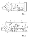
- the first exemplary embodiment according to FIG. 1 comprises a source 1, consisting of an alternating voltage source 2, which for example represents an alternating voltage network, and a bridge rectifier 3.
- This source 1 outputs a pulsating direct voltage at two connections 4, 5, through which energy via lines 6, 7 in a switching power supply 8 is fed.
- the switched-mode power supply 8 and a consumer fed by it can have different constructions known per se.
- the circuit arrangement according to FIG. 1 furthermore has a control circuit 9 which, in operation, also has a line 10 from the switching power supply 8 Energy is supplied.
- the switching power supply is controlled by the control circuit 9 in a manner known per se via a control line 11.
- the control circuit 9 Since when the circuit arrangement, i.e. when the source 1 is switched on, the switching power supply 8 of the control circuit 9 initially does not supply any energy via the line 10, the control circuit 9 cannot go into operation without additional measures, so that in turn the switching power supply 8 cannot be brought into operation.
- the control circuit 9 is therefore supplied with energy via a starter circuit 12 during a transition period, by means of which the function of the control circuit 9 is ensured until the energy supply via the switching power supply 8 and the line 10 is effective.
- the starter circuit 12 comprises a capacitive voltage divider consisting of two capacitors 13, 14, the capacitance values of which are selected in accordance with the ratio between the voltage output by the source 1 and the supply voltage required by the control circuit 9.
- connection point between the capacitors 13, 14 is designed as a tap 15, from which a feed current for the control circuit 9 can be drawn via a rectifier element 16.
- capacitors 13, 14 are charged.
- the energy flowing into the capacitor 14 is available via the rectifier element 16 for starting up the control circuit 9, for example for oscillating an oscillator contained therein.
- the control circuit 9 is thus able, even without prior function, of the switching power supply 8 to control it via the control line 11 in such a way that it begins to supply energy via the line 10.
- the further function of the control circuit 9 is then ensured by the energy via the line 10.
- a smoothing capacitor 29 and a zener diode 30 are arranged in parallel with one another in order to smooth or limit the supply voltage supplied to the control circuit 9 between the lines 7 and 10.
- a second rectifier element 17 is arranged in a polarity opposite to the polarity of the source between a connection 5 of the source 1 and the tap 15. This rectifier element is used in particular to avoid negative charges on the capacitor 14 when the source 1 is switched off.
- the supply current from the tap 15 is guided by the starter circuit via a limiting impedance 18.
- a limiting impedance 18 In the simplest case, an ohmic resistor is used as such, the losses occurring therein being acceptable, since they only occur briefly when the circuit arrangement is started up.
- the capacitive voltage divider from the capacitors 13, 14 serves in the circuit arrangement according to FIG. 1 at the same time as a charging capacitor for the DC voltage supply of the switched-mode power supply 8 by the source 1. This double utilization of the components serves for an inexpensive construction of the circuit arrangement.
- Fig. 2 shows a further embodiment of the invention, in which the switching power supply 8 is designed as a step-up converter with a series connection of an inductor 20 and a switch element 21, on which a voltage for feeding a load can be tapped via a third rectifier element 22, which is shown in Fig 2 is shown schematically as an ohmic resistor 23.
- the capacitive voltage divider 13, 14 of the starter circuit 12 is arranged in parallel with the load 23. Otherwise, the circuit elements already shown in FIG. 1 are again provided with identical reference numerals.
- the switching power supply 8 designed as a step-up converter according to FIG. 2 is also provided with a supply circuit for supplying energy to the control circuit 9 during operation, as has already been described in substantial parts in German Patent 32 12 147.
- the inductance 20 of the switching power supply 8 connected to the first connection 4 of the source 1 has a tap 24 which is connected to the second connection 5 of the source 1 via a capacitor 25 and a diode 26 which is polarized in the reverse direction with respect to the source 1. From the connection point 27 between the capacitor 25 and the diode 26, a second diode 28 - polarized in the direction of flow - leads to the line 10, via which the control circuit 9 is supplied with energy from the capacitor 25 during operation.
- the control circuit 9 also includes the driver circuit 31, which emits a switching signal for the switch element 21 on the control line 11 and is fed with energy via the line 10 and a connection 32 to the second connection 5 of the source 1.
- the starter circuit is also connected to the line 10 via the rectifier element 16.
- the driver circuit 31 When the circuit arrangement is put into operation, ie when the source 1 is switched on, the driver circuit 31, which is initially still out of operation, flows and the switch element is thus blocked 21 a current through the inductor 20, the third rectifier element 22 and the capacitive voltage divider 13, 14. As a result, its capacitor 14 is charged to an initial voltage which is sufficient to charge the smoothing capacitor 29 on the one hand via the rectifier element 16 and on the other hand to drive the driver circuit 31 bring to.
- the switch circuit 21 and the inductance 20 of the switched-mode power supply 8 also supply the capacitor 25, and thus the diodes 26, 28 and the smoothing capacitor 29, to the driver circuit 31 in the end for energy for further operation.
- the capacitive voltage divider 13, 14 also serves to smooth the voltage supplied to the load 23, as a result of which these circuit elements can also be used economically in this circuit arrangement.
Landscapes
- Engineering & Computer Science (AREA)
- Power Engineering (AREA)
- Dc-Dc Converters (AREA)
- Rectifiers (AREA)
Applications Claiming Priority (2)
| Application Number | Priority Date | Filing Date | Title |
|---|---|---|---|
| DE4125510A DE4125510A1 (de) | 1991-08-01 | 1991-08-01 | Schaltungsanordnung mit einem schaltnetzteil |
| DE4125510 | 1991-08-01 |
Publications (2)
| Publication Number | Publication Date |
|---|---|
| EP0525898A2 true EP0525898A2 (fr) | 1993-02-03 |
| EP0525898A3 EP0525898A3 (en) | 1993-08-25 |
Family
ID=6437500
Family Applications (1)
| Application Number | Title | Priority Date | Filing Date |
|---|---|---|---|
| EP19920202296 Withdrawn EP0525898A3 (en) | 1991-08-01 | 1992-07-24 | Circuit arrangement with a switching power supply |
Country Status (4)
| Country | Link |
|---|---|
| US (1) | US5282126A (fr) |
| EP (1) | EP0525898A3 (fr) |
| JP (1) | JPH05207734A (fr) |
| DE (1) | DE4125510A1 (fr) |
Cited By (5)
| Publication number | Priority date | Publication date | Assignee | Title |
|---|---|---|---|---|
| EP0584873A1 (fr) * | 1992-08-26 | 1994-03-02 | Koninklijke Philips Electronics N.V. | Moyens de temporisation pour retarder l'amerçaged'un convertisseur à la mise sous tension |
| WO1995012840A1 (fr) * | 1993-11-03 | 1995-05-11 | Braun Aktiengesellschaft | Alimentation a decoupage |
| AT405703B (de) * | 1996-07-23 | 1999-11-25 | Siemens Ag Oesterreich | Netzgerät |
| EP2169816A1 (fr) * | 2008-09-27 | 2010-03-31 | Osram Gesellschaft mit Beschränkter Haftung | Circuit de démarrage pour un circuit intégré d'un contrôleur de correction du facteur de puissance |
| US11831234B2 (en) * | 2019-08-12 | 2023-11-28 | Eldolab Holding B.V. | Neutral-less power supply with buck converter |
Families Citing this family (38)
| Publication number | Priority date | Publication date | Assignee | Title |
|---|---|---|---|---|
| DE59308738D1 (de) * | 1992-09-30 | 1998-08-13 | Siemens Ag | Verfahren zur Vorsteuerung eines Schaltnetzteiles zum Ausgleich von Schwankungen der Speisespannung und Schaltungsanordnung zur Durchführung des Verfahrens |
| CA2103982C (fr) * | 1993-08-12 | 1997-05-27 | Ivan Meszlenyi | Circuit d'amorcage et d'alimentation pour convertisseurs d'alimentation a resonance |
| US5483436A (en) * | 1993-08-30 | 1996-01-09 | General Electric Company | Gate drive power supply operable from a source of unregulated DC electric power |
| US5640317A (en) * | 1995-06-15 | 1997-06-17 | Supertax, Inc. | High voltage start-up circuit and method therefor |
| JP2000116027A (ja) * | 1998-03-10 | 2000-04-21 | Fiderikkusu:Kk | 電源装置 |
| IL125328A0 (en) * | 1998-07-13 | 1999-03-12 | Univ Ben Gurion | Modular apparatus for regulating the harmonics of current drawn from power lines |
| US6301135B1 (en) | 1999-03-01 | 2001-10-09 | Texas Instruments Incorporated | Isolated switching-mode power supply control circuit having secondary-side controller and supervisory primary-side controller |
| US6272025B1 (en) | 1999-10-01 | 2001-08-07 | Online Power Supply, Inc. | Individual for distributed non-saturated magnetic element(s) (referenced herein as NSME) power converters |
| US6636107B2 (en) * | 2000-03-28 | 2003-10-21 | International Rectifier Corporation | Active filter for reduction of common mode current |
| JP2003339164A (ja) | 2002-05-22 | 2003-11-28 | Hitachi Industrial Equipment Systems Co Ltd | スイッチング電源回路、及びインバータ装置 |
| US6952355B2 (en) * | 2002-07-22 | 2005-10-04 | Ops Power Llc | Two-stage converter using low permeability magnetics |
| DE102005025626A1 (de) | 2005-06-03 | 2006-12-07 | Patent-Treuhand-Gesellschaft für elektrische Glühlampen mbH | Elektronisches Vorschaltgerät für mindestens eine Lampe |
| US9197132B2 (en) | 2006-12-01 | 2015-11-24 | Flextronics International Usa, Inc. | Power converter with an adaptive controller and method of operating the same |
| US7468649B2 (en) * | 2007-03-14 | 2008-12-23 | Flextronics International Usa, Inc. | Isolated power converter |
| US7808219B2 (en) * | 2007-11-26 | 2010-10-05 | Honeywell International Inc. | Method and apparatus of capacitor divider based offline AC-DC converter |
| JP2008125355A (ja) * | 2008-02-25 | 2008-05-29 | Hitachi Industrial Equipment Systems Co Ltd | スイッチング電源回路、及びインバータ装置 |
| DE102008049677B4 (de) * | 2008-09-30 | 2014-09-18 | Infineon Technologies Ag | Spannungsversorgung in einer Schaltungsanordnung mit einem Halbleiterschaltelement |
| CN102217181B (zh) * | 2008-11-14 | 2014-09-03 | 伟创力国际美国公司 | 用于同步整流器的驱动器以及采用该驱动器的功率转换器 |
| US9088216B2 (en) | 2009-01-19 | 2015-07-21 | Power Systems Technologies, Ltd. | Controller for a synchronous rectifier switch |
| WO2010083511A1 (fr) * | 2009-01-19 | 2010-07-22 | Flextronics International Usa, Inc. | Contrôleur pour un convertisseur de puissance |
| US9019061B2 (en) | 2009-03-31 | 2015-04-28 | Power Systems Technologies, Ltd. | Magnetic device formed with U-shaped core pieces and power converter employing the same |
| US8514593B2 (en) | 2009-06-17 | 2013-08-20 | Power Systems Technologies, Ltd. | Power converter employing a variable switching frequency and a magnetic device with a non-uniform gap |
| US9077248B2 (en) | 2009-06-17 | 2015-07-07 | Power Systems Technologies Ltd | Start-up circuit for a power adapter |
| US8643222B2 (en) * | 2009-06-17 | 2014-02-04 | Power Systems Technologies Ltd | Power adapter employing a power reducer |
| US8638578B2 (en) | 2009-08-14 | 2014-01-28 | Power System Technologies, Ltd. | Power converter including a charge pump employable in a power adapter |
| US8976549B2 (en) * | 2009-12-03 | 2015-03-10 | Power Systems Technologies, Ltd. | Startup circuit including first and second Schmitt triggers and power converter employing the same |
| US8520420B2 (en) | 2009-12-18 | 2013-08-27 | Power Systems Technologies, Ltd. | Controller for modifying dead time between switches in a power converter |
| US8787043B2 (en) * | 2010-01-22 | 2014-07-22 | Power Systems Technologies, Ltd. | Controller for a power converter and method of operating the same |
| US9246391B2 (en) | 2010-01-22 | 2016-01-26 | Power Systems Technologies Ltd. | Controller for providing a corrected signal to a sensed peak current through a circuit element of a power converter |
| US20110239008A1 (en) * | 2010-03-26 | 2011-09-29 | Lam Kean W | Power Adapter Having a Universal Serial Bus Hub |
| JP2011167068A (ja) * | 2011-06-01 | 2011-08-25 | Hitachi Industrial Equipment Systems Co Ltd | スイッチング電源回路、及びインバータ装置 |
| TW201328152A (zh) * | 2011-12-28 | 2013-07-01 | Ushijima Masakazu | 輔助電源產生電路 |
| US9214264B2 (en) | 2012-07-16 | 2015-12-15 | Power Systems Technologies, Ltd. | Magnetic device and power converter employing the same |
| US9379629B2 (en) | 2012-07-16 | 2016-06-28 | Power Systems Technologies, Ltd. | Magnetic device and power converter employing the same |
| US9099232B2 (en) | 2012-07-16 | 2015-08-04 | Power Systems Technologies Ltd. | Magnetic device and power converter employing the same |
| US9106130B2 (en) | 2012-07-16 | 2015-08-11 | Power Systems Technologies, Inc. | Magnetic device and power converter employing the same |
| US9837893B2 (en) | 2013-07-31 | 2017-12-05 | Fairchild Korea Semiconductor Ltd. | Charge pump and switch control circuit |
| WO2025027022A1 (fr) * | 2023-08-03 | 2025-02-06 | Signify Holding B.V. | Convertisseur c.c./c.c. dérivé abaisseur ou abaisseur/élévateur à deux sorties séparées et commande quasi-découplée |
Family Cites Families (8)
| Publication number | Priority date | Publication date | Assignee | Title |
|---|---|---|---|---|
| DE2638225A1 (de) * | 1976-08-25 | 1978-03-02 | Olympia Werke Ag | Schaltnetzteil |
| CA1231131A (fr) * | 1984-12-13 | 1988-01-05 | Brian Lees | Technique d'amorcage de diac defectueux |
| US4887199A (en) * | 1986-02-07 | 1989-12-12 | Astec International Limited | Start circuit for generation of pulse width modulated switching pulses for switch mode power supplies |
| US4695936A (en) * | 1986-02-07 | 1987-09-22 | Astec Components, Ltd. | Switching mode power supply start circuit |
| DE3612147A1 (de) * | 1986-04-10 | 1987-10-15 | Philips Patentverwaltung | Schaltungsanordnung zur erzeugung einer gleichspannung aus einer sinusfoermigen eingangsspannung |
| DE3732790A1 (de) * | 1987-09-29 | 1989-04-13 | Thomson Brandt Gmbh | Schaltnetzteil |
| US4910654A (en) * | 1989-01-10 | 1990-03-20 | Uniphase Corporation | Current limiting scheme for the AC input circuit to a switch mode power supply |
| DE3930432A1 (de) * | 1989-09-12 | 1991-05-16 | Siemens Ag | Schaltnetzteil |
-
1991
- 1991-08-01 DE DE4125510A patent/DE4125510A1/de not_active Withdrawn
-
1992
- 1992-07-24 EP EP19920202296 patent/EP0525898A3/de not_active Withdrawn
- 1992-07-30 JP JP4203742A patent/JPH05207734A/ja active Pending
- 1992-08-03 US US07/924,277 patent/US5282126A/en not_active Expired - Fee Related
Cited By (6)
| Publication number | Priority date | Publication date | Assignee | Title |
|---|---|---|---|---|
| EP0584873A1 (fr) * | 1992-08-26 | 1994-03-02 | Koninklijke Philips Electronics N.V. | Moyens de temporisation pour retarder l'amerçaged'un convertisseur à la mise sous tension |
| WO1995012840A1 (fr) * | 1993-11-03 | 1995-05-11 | Braun Aktiengesellschaft | Alimentation a decoupage |
| US5708572A (en) * | 1993-11-03 | 1998-01-13 | Braun Aktiengesellschaft | Switched-mode power supply |
| AT405703B (de) * | 1996-07-23 | 1999-11-25 | Siemens Ag Oesterreich | Netzgerät |
| EP2169816A1 (fr) * | 2008-09-27 | 2010-03-31 | Osram Gesellschaft mit Beschränkter Haftung | Circuit de démarrage pour un circuit intégré d'un contrôleur de correction du facteur de puissance |
| US11831234B2 (en) * | 2019-08-12 | 2023-11-28 | Eldolab Holding B.V. | Neutral-less power supply with buck converter |
Also Published As
| Publication number | Publication date |
|---|---|
| EP0525898A3 (en) | 1993-08-25 |
| DE4125510A1 (de) | 1993-02-04 |
| JPH05207734A (ja) | 1993-08-13 |
| US5282126A (en) | 1994-01-25 |
Similar Documents
| Publication | Publication Date | Title |
|---|---|---|
| EP0525898A2 (fr) | Dispositif de circuit avec une alimentation à découpage | |
| DE2850841C2 (de) | Schaltungsanordnung für ein integrierbares elektronisches Relais | |
| DE3687999T2 (de) | Reihenschwingkreis-umrichter. | |
| DE19545154C2 (de) | Stromversorgungseinrichtung | |
| EP0241976B1 (fr) | Circuit pour générer une tension continue à partir d'une tension d'entrée sinusoidale | |
| DE3615052C2 (fr) | ||
| EP0309892A2 (fr) | Alimentation de puissance à découpage | |
| DE2705968A1 (de) | Starter- und vorschaltanordnung fuer gasentladungslampe | |
| DE69118501T2 (de) | Wechselrichteranordnung | |
| DE2513005B2 (de) | Netzgerät zur Transformation einer ungeregelten, pulsierenden Eingangsspannung in eine stabilisierte Gleichspannung | |
| EP0991171A2 (fr) | Convertisseur à récupération | |
| DE2320128B2 (de) | Zerhacker | |
| EP0247409B1 (fr) | Alimentation à commutation avec convertisseur à courant continu à découpage sur le primaire | |
| DE102004016927A1 (de) | Verfahren zur Strom- und Spannungsregelung für ein Schaltnetzteil | |
| DE2613423B2 (de) | Elektronisches Schaltgerät | |
| EP0268043A2 (fr) | Circuit d'alimentation de courant continu pour lampe fluorescente | |
| EP0326220A2 (fr) | Disposition de circuit pour alimenter une charge | |
| DE10254408A1 (de) | Ladungsgepumpte Gleichsignal-Vorspannungsversorgung | |
| DE2453979A1 (de) | Spannungswandler, insbesondere fuer elektrofahrzeuge | |
| DE4008663C1 (fr) | ||
| DE3535020A1 (de) | Wechselstrom-gleichstromwandler | |
| DE2452887A1 (de) | Hochgleichspannungsgenerator | |
| DE3942645C2 (fr) | ||
| DE3311737C2 (de) | Elektronisches Schaltnetzteil | |
| EP0320605B1 (fr) | Alimentation électronique à découpage avec un convertisseur à inductance |
Legal Events
| Date | Code | Title | Description |
|---|---|---|---|
| PUAI | Public reference made under article 153(3) epc to a published international application that has entered the european phase |
Free format text: ORIGINAL CODE: 0009012 |
|
| AK | Designated contracting states |
Kind code of ref document: A2 Designated state(s): DE FR GB |
|
| PUAL | Search report despatched |
Free format text: ORIGINAL CODE: 0009013 |
|
| AK | Designated contracting states |
Kind code of ref document: A3 Designated state(s): DE FR GB |
|
| 18D | Application deemed to be withdrawn |
Effective date: 19940226 |