EP0525996A2 - Verfahren zur Auflösungsumwandlung - Google Patents
Verfahren zur Auflösungsumwandlung Download PDFInfo
- Publication number
- EP0525996A2 EP0525996A2 EP92306063A EP92306063A EP0525996A2 EP 0525996 A2 EP0525996 A2 EP 0525996A2 EP 92306063 A EP92306063 A EP 92306063A EP 92306063 A EP92306063 A EP 92306063A EP 0525996 A2 EP0525996 A2 EP 0525996A2
- Authority
- EP
- European Patent Office
- Prior art keywords
- input pixels
- pixels
- intensity value
- output pixel
- selected output
- Prior art date
- Legal status (The legal status is an assumption and is not a legal conclusion. Google has not performed a legal analysis and makes no representation as to the accuracy of the status listed.)
- Granted
Links
Images


Classifications
-
- G—PHYSICS
- G06—COMPUTING OR CALCULATING; COUNTING
- G06T—IMAGE DATA PROCESSING OR GENERATION, IN GENERAL
- G06T3/00—Geometric image transformations in the plane of the image
- G06T3/40—Scaling of whole images or parts thereof, e.g. expanding or contracting
Definitions
- the present invention relates generally to a method of resolution conversion for use in a system capable of manipulating digital images represented by a plurality of original image pixels, and more specifically to a method, capable of being used in an electroreprographic machine, for deriving an intensity value of a selected output pixel in a bitmap, the bitmap including the selected output pixel mapped to a plurality of correlated, neighboring input pixels.
- Image information is commonly generated in a bitmap format at a particular scale, and resolution K x L x b, corresponding to a desired printer output, where K is a number of spots per unit of length in one dimension, L is a number of spots per unit length in the other dimension, and b is the depth of each pixel, in number of levels.
- This bitmap is present for every color separation of the output device, i.e., 4 bitmaps for a 4-color output device, 3 for a 3-color, 2 for a 2-color and 1 for a black and white output device.
- image data comprising a bitmap to be printed is provided to a printer suitable for printing at 300 spots per inch (spi) in both dimensions, at a one bit depth giving 2 levels.
- spi spots per inch
- Many considerations drive this single selection of resolution, including the desirability of providing only a limited number of fonts (alphanumeric bitmaps) so as to use only a limited amount of storage space.
- Common software packages available on personal computers or for operation of input scanners for document creation also usually provide only a single resolution output.
- Printer resolutions are available over a range, for example, from less than 200 spi to to more than 600 spi. Resolutions vary for a number of reasons, generally related to the quality of the output image. Simply printing a 300 spi bitmap at 400 spi or 600 spi is undesirable however, since the image will be reduced substantially in size on the output page or display. On the other hand, printing a 400 spi bitmap at 300 spi is undesirable since the image is simply enlarged, and commonly is visibly distorted at the lesser resolution. It would be highly desirable to provide the capability of printing any image at any resolution, while selecting the output size.
- a method for use in a system of the type capable of manipulating digital images represented by a plurality of original image pixels.
- the system has a memory for storing images and means for outputting the images.
- the method includes a step of deriving an intensity value for a selected output pixel in a set of output pixels from a plurality of input pixels in a set of input pixels, each of the plurality of input pixels having a corresponding intensity value contributing to the intensity value of the selected output pixel.
- the step of deriving the intensity value of the selected output pixel preferably comprises the steps of mapping, in the memory, the set of output pixels to the set of input pixels so that each of the plurality of input pixels is adjacent the selected output pixel, as well as reading the plurality of input pixels from the memory. After determining a correlation value for each of the plurality of input pixels with a correlation function, the correlation values of the plurality of input pixels can be summed with the corresponding respective intensity values of the plurality of input pixels to obtain the intensity value of the selected output pixel.
- the step of deriving the intensity value of the selected output pixel comprises the above-mentioned mapping and reading steps as well as a step in which a multi-bit index word is formed from the corresponding intensity values of the plurality of input pixels.
- This aspect further comprises a step of providing a table having a plurality of preselected reference words and intensity values respectively assigned thereto--the plurality of preselected reference words and respectively assigned intensity values being ordered in a sequence, the sequence varying in accordance with a correlation function.
- the intensity value or the selected output pixel can be determined by matching the multi-bit index word with one of the preselected reference words and its respectively assigned intensity value.
- the correlation function is a Gaussian-like correlation function, which Gaussian-like correlation function is characterized by the expression:
- the method further comprises the steps of designating a pivot point (X c ,Y c ) for the selected output pixel and disposing the centers of the plurality of input pixels substantially within a window centered about the pivot point.
- the size of the window which size can be optimized, varies as a function of the correlation function.
- the window can be characterized by an ellipse.
- the conversion technique is conceived generically, i. e. the conversion can use a single correlation function to solve one of many resolution cases. Consequently, each conversion can be performed, with a high degree of precision and accuracy, over a broad range of resolutions.
- the input image can be magnified or reduced, with great clarity, for both integral and nonintegral values.
- the conversion technique can be performed easily and inexpensively since it can be readily implemented in software.
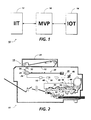
- the apparatus 10 comprises an image input terminal (IIT) 12, image output terminal (IOT) 14, and a main video processor (MVP) 16.
- the IIT 12 includes a scanning section 18 having an automatic document handler (ADH) 20 for automatically and sequentially placing one or more documents on a transparent platen 22.
- the scanning section 18 employs one or more linear scanning arrays 24, which arrays 24 may comprise charge coupled devices (CCDs) supported below and in scanning relation to the platen by a carriage 26.
- CCDs charge coupled devices
- the carriage 26 can be reciprocated by conventional reciprocating means 28.
- the IIT 12 could be an input other than the scanning section 18, such as a computer workstation, a facsimile device, a CD ROM, or other like I/O devices.
- a suitable lens 32 is provided to focus arrays 24 on a line-like segment of the platen 22 and the documents resting thereon. Additionally, a suitable lamp 34 illuminates the document line being scanned. Arrays 24 provide electrical image data or pixels representative of the document image scanned which are inputted to the MVP 16 by a suitable IIT interface (not shown).
- the IOT 14 includes a raster output scanner (ROS) 36 having a suitable source of high intensity light, such as laser 38, modulated in accordance with the content of the image data as by an acousto-optic modulator 40 to provide zero and first order imaging beams.
- ROS raster output scanner
- the image data may be used for purposes other than printing copies, as for example, the image data could be transmitted from the MVP 16 to one of a number of devices, such as a CRT or a thermal ink jet printer. Moreover the image data could be transmitted from the MVP 16 to another location, via a communication channel (not shown), or stored for later use, etc.
- the imaging beam is scanned across a photoreceptor 42 at an exposing station 44 by a scanning polygon 46 to expose the previously charged photoreceptor 42 and create a latent electrostatic image or the document represented by the image signals to modulator 40.
- Suitable means (not shown) are employed to focus the beam on the photoreceptor 42.
- the exemplary electroreprographic machine 10 illustrated in Figure 2 employs a removable processing cartridge 48 including the photoreceptor 42, which in one example comprises a belt like member 50, the outer periphery of the belt like member 50 being coated with a suitable photoconductive material 52.
- the belt 50 moves the photoconductive surface 52, in a known manner, through a charging station 54 wherein the belt 50 is uniformly charged with an electrostatic charge placed on the photoconductive surface 52 by charge corotron 56 in known manner preparatory to imaging.
- the belt 50 is driven to the exposure station 44 wherein the charged photoconductive surface 52 is exposed to line-by-line scanning of the ROS 36, whereby the charge is selectively dissipated in the light exposed regions to record the original input image in the form of an electrostatic latent image.
- the resolution conversion method disclosed of the present invention can be implemented by writing image data of the input image into a memory section 100, which memory section 100 in one example is a page buffer.
- digital image information in the form of image data picture elements ("pixels"), digital voltage representations of image intensity at discrete locations in an image, is provided from the IIT 12.
- image data pixels constitute the response of photosites indicating the intensity of light detected at the photosites over a given period.
- the partial bitmap 101 comprises a portion of an array 106 of i x j output pixels 108 mapped on a portion of an array 102 of i x j input pixels 104.
- the arrays 102, 106 are characterized by a fast scan direction and a slow scan direction, and the pixels 104, 108 are positioned along scan lines.
- the fast and slow scan directions are respectively indicated by the by arrows 110 and 112.
- arrays 102, 106 are defined by respective resolutions in the fast scan direction and the slow scan direction.
- the pixels 104, 108 will possess characteristic intensities, ranging from white to black.
- the method can be performed with binary images as well as images having various levels of halftones. Additionally, it should be appreciated that the method is equally applicable to resolution conversions of black/white or color images.
- a first step is directed toward determining the spatial relationship between the input image and the output image.
- the ratio of the input to output resolution is employed to determine the output pixel size, number of pixels per scan line and number of scan lines in the output image as follows:
- a second step is directed toward determining a center or Pivot Point (X c ,Y c ) of the cross-hatched, selected output pixel 108 with the following equations:
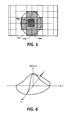
- a window of input pixels 104 ( Figure 5), centered about the Pivot Point (X c , Y c ), is designated by the numeral 114.
- the window 114 is defined by input pixels 104 whose respective centers are within a predetermined area, such as an ellipse 115 having its center at the Pivot Point (X c , Y c ).
- the ellipse 115 preferably corresponds to at least a portion of a base of the Gaussian-like correlation function of Figure 6.
- the resolution conversion is optimized when the perimeter of the prescribed ellipse extends a distance of 3a.
- 3a refers to a horizontal distance measured from the center of the correlation function of Figure 6.
- the size of the window 114 varies as a function of the sizes of both the input pixels 104 and output pixels 108.
- Experimentation indicates that the size of window 114 is optimized by use of the following equations:
- window 114 can be further optimized by use of the parameters Q x and Qy as follows: In the above equations (as well as in all of the equations below) the operator " * " is used to designate multiplication. Additionally, in Equations 7A-10A, Q x and Qy are typically in the range of 0.85-5.0.
- the input pixels 14 thereof can be correlated with a correlating function.
- the properties of the correlating function closely approximate the correlation of the neighboring input pixels 104 in the vicinity of the Pivot Point (X c , Y c ). It has been observed, through experimentation, that the input pixels 104 closest to the Pivot Point (X c , Y c ) of a selected output pixel 108 will afford a relatively greater contribution to the intensity of the selected output pixel 108 than will the input pixels 104 that are farther from the Point (X c , Y c ). Indeed, for continuous tone images, a Gaussian-like contribution from neighboring input pixels 104 can be observed. Based on this observation, the following Gaussian-like correlation function can be used to correlate the input pixels 104 in the given window 114: where,
- W(i,j) could be defined by a correlation function other than a Gaussian-like correlation function.
- W(i,j) could assume a form similar to that of other probabilistic functions, such as sin u/u.
- binary 600 x 600 spi images were converted to and printed at 400 x 400 spi images having two intermediate levels of gray.
- the method is neither limited to binary images, nor images having just two intermediate levels of gray.
- moire patterns were present. It stands to reason that the moire patterns could be alleviated or substantially eliminated by using an adaptive screen detection and diffusion technique along with the method of the present invention.
- the size of the window 114 was optimized to generate the most accurate representation of the original image.
- an iterative technique was employed to minimize error between an image of an original and a corresponding "round robin" image.
- round robin conversion refers to converting the image to a selected resolution and then converting it back to the original resolution.
- the total error resulting from each iteration of the round robin was calculated and a new window size determined with a known gradient technique.
- the size of window 114 converges to a solution in which the total error is minimized. It is contemplated that for certain correlation functions other than Gaussian-like correlation functions, non-iterative optimization techniques could be employed.
- Equatons 11-14 can be solved with a network employing conventional hardware (not shown) or with processing means using software.
- a software implementation can be accomplished with a combination of the memory section 100 and a CPU 116, such as a MC68020 microprocessor manufactured by Motorola Corporation.
- the software implementation is accomplished by matching a characteristic index word, "L,” constructed from correlated intensities of the input pixels 104 of window 114 with a reference word (Table 1), each reference word having an intensity value assigned thereto.
- Hardware or software implementation of the present method is preferably achieved by repetitively solving Z for one of four generic cases.
- the four generic cases representing four generic windows 114 formed during the method, are shown. Since the conversion of the present method is performed similarly for each of the four cases, detailed explanation of the method is reserved to just one of the four cases, namely the case illustrated by Figure 7A and the accompanying first block of pseudo-code shown below.
- the input pixels 104 of the window 114 are designated B1 through MSB, these designations representing the sequence from the least significant bit B1 to the most significant bit MSB.
- each of the input pixels 104 of the window 114 is indicated by use of an exemplary pointing arrangement in which the pointer is moved relative to one of the input pixels 104 centrally disposed about the Pivot Point (X c Y c ).
- the bit order assignment of each input pixel 104 in the window 114 is made in general accordance with the degree to which each input pixel 104 correlates to the other surrounding input pixels 104.
- the pointer (K1,K2) is moved a preselected number of pixel lengths, relative to a centrally disposed input pixel 104, the centrally disposed input pixel 104 being substantially coincidental with the selected output pixel 108.
- the pointer can be moved in one of four directions, namely left, right, up or down. Movement of the pointer to the left or up is arbitrarily considered negative while movement of the pointer to the right or down is arbitrarily considered positive.
- the centrally disposed input pixel is designated B7, and MSB is assigned to the input pixel 104 in the upper left-hand corner. Since the MSB is one input pixel length to the left of B7, and one input pixel length above B7, the pointer position for the MSB is indicated as (K1-1,K2-1). Using similar reasoning, the pointer position of the input pixel 104 disposed directly above B7 by one input pixel length, i. e. B10, is indicated as (K1,K2-1). Referring to the bit designations of Figure 7A, along with the two pointer position assignment examples for MSB and B10, one of ordinary skill in the art can readly reason what the pointer assignments should be for B1-B9.
- each window 114 preferably reflects the correlation of a set of input pixels 104 to a respective output pixel 108 via the Gaussian-like correlation function. Moreover, the correlated relationship among the bits is reflected in the index word L formed from the bits. As mapping of the input pixels 104 proceeds from left to right and top to bottom, the bits B1-MSB of each window 114 preferably maintain substantially the same spatial relationship, relative to a respective pivot point (X c ,Y c ). During the software implementation, it may be necessary to rearrange the bit order in a given window 114 to maintain this desired spatial relationship.
- B1-MSB of Figures 7A-7D are rotated about axes of symmetry with respect to B1-MSB of Figure 7A.
- the index word L which characterizes the intensity value of the selected output pixel 108 in Figure 7A, is constructed by first loading the register, including bit locations ao-aii - ( Figure 8A), with the value for MSB in a o and 1 s in a 1 -a 11 . While the intensity values of B1-MSB are binary in the present conversion example, in other contemplated examples, B1-MSB could be gray scale intensity values. Moreover, while the example illustrates 11 input pixels 104 being loaded into the register, the number of pixels 104 used to define window 114 and the size of register could both be increased without altering the concept underlying the method of the present invention.
- L is matched with a reference word in the following Look-Up Table 1:
- the Table 1 is developed by down-loading, into the processing means 116, each of the various reference words that L can assume, and assigning a suitable intensity value to each of the reference words.
- the distribution of the assigned intensity values in the Table 1 discretely varies as a function of W(i,j) of the Gaussian-like correlation function.
- L is determined for a designated window 114 and matched with a reference word in Table 1.
- the reference words of Table 1 are ordered in a sequence and intensity values are assigned respectively thereto. Since the order of the sequence varys in accordance with the correlation function of Equation 11, the assigned intensity value corresponding to the matched reference word closely approximates the optimum intensity value for the selected output pixel 108 at a desired resolution.
- the above-described technique for one selected output pixel 108 can be performed repetitively for each output pixel 108 in the bitmap 101 so that an optimum output image can be delivered to the IOT at the desired resolution.
Landscapes
- Physics & Mathematics (AREA)
- General Physics & Mathematics (AREA)
- Engineering & Computer Science (AREA)
- Theoretical Computer Science (AREA)
- Image Processing (AREA)
- Controls And Circuits For Display Device (AREA)
- Dot-Matrix Printers And Others (AREA)
- Editing Of Facsimile Originals (AREA)
Applications Claiming Priority (2)
| Application Number | Priority Date | Filing Date | Title |
|---|---|---|---|
| US07/737,297 US5282051A (en) | 1991-07-29 | 1991-07-29 | Apparatus and method for performing resolution conversion on image data with auto correlation |
| US737297 | 1991-07-29 |
Publications (3)
| Publication Number | Publication Date |
|---|---|
| EP0525996A2 true EP0525996A2 (de) | 1993-02-03 |
| EP0525996A3 EP0525996A3 (en) | 1994-09-14 |
| EP0525996B1 EP0525996B1 (de) | 1998-10-07 |
Family
ID=24963354
Family Applications (1)
| Application Number | Title | Priority Date | Filing Date |
|---|---|---|---|
| EP92306063A Expired - Lifetime EP0525996B1 (de) | 1991-07-29 | 1992-07-01 | Verfahren zur Umwandlung der Bildauflösung |
Country Status (5)
| Country | Link |
|---|---|
| US (1) | US5282051A (de) |
| EP (1) | EP0525996B1 (de) |
| JP (1) | JP3128091B2 (de) |
| CA (1) | CA2063472C (de) |
| DE (1) | DE69227223T2 (de) |
Cited By (4)
| Publication number | Priority date | Publication date | Assignee | Title |
|---|---|---|---|---|
| WO1994027239A1 (en) * | 1993-05-10 | 1994-11-24 | Apple Computer, Inc. | Resolution independent methods for rendering a graphic image on a display device |
| EP0786738A3 (de) * | 1995-09-08 | 1997-12-10 | Quantel Limited | Bildverarbeitungssystem |
| WO1999056246A1 (en) * | 1998-04-24 | 1999-11-04 | Silicon Image, Inc. | Scaling multi-dimensional signals using variable weighting factors |
| EP1003129A3 (de) * | 1998-11-19 | 2000-12-13 | Electrosonic Limited | Verfahren und Gerät zur Grössenänderung eines Videobildes |
Families Citing this family (25)
| Publication number | Priority date | Publication date | Assignee | Title |
|---|---|---|---|---|
| US5341226A (en) * | 1993-04-22 | 1994-08-23 | Xerox Corporation | Automatic image segmentation for color documents |
| US5696851A (en) * | 1993-04-30 | 1997-12-09 | Comsat Corporation | Codeword-dependent post-filtering for vector quantization-based image compression |
| US5359423A (en) * | 1993-12-17 | 1994-10-25 | Xerox Corporation | Method for statistical generation of density preserving templates for print enhancement |
| US5732204A (en) * | 1994-02-01 | 1998-03-24 | Ricoh Company, Ltd. | Method and device for 3D image processing |
| US5473376A (en) * | 1994-12-01 | 1995-12-05 | Motorola, Inc. | Method and apparatus for adaptive entropy encoding/decoding of quantized transform coefficients in a video compression system |
| US5818504A (en) * | 1995-11-27 | 1998-10-06 | Hewlett-Packard Company | Adjustment of dot size for laser imagers |
| JP3210248B2 (ja) * | 1996-04-25 | 2001-09-17 | キヤノン株式会社 | 画像処理装置及びその方法 |
| US6786420B1 (en) | 1997-07-15 | 2004-09-07 | Silverbrook Research Pty. Ltd. | Data distribution mechanism in the form of ink dots on cards |
| US6618117B2 (en) | 1997-07-12 | 2003-09-09 | Silverbrook Research Pty Ltd | Image sensing apparatus including a microcontroller |
| US6803989B2 (en) * | 1997-07-15 | 2004-10-12 | Silverbrook Research Pty Ltd | Image printing apparatus including a microcontroller |
| US6624848B1 (en) | 1997-07-15 | 2003-09-23 | Silverbrook Research Pty Ltd | Cascading image modification using multiple digital cameras incorporating image processing |
| US20040119829A1 (en) * | 1997-07-15 | 2004-06-24 | Silverbrook Research Pty Ltd | Printhead assembly for a print on demand digital camera system |
| AUPO850597A0 (en) * | 1997-08-11 | 1997-09-04 | Silverbrook Research Pty Ltd | Image processing method and apparatus (art01a) |
| US6879341B1 (en) | 1997-07-15 | 2005-04-12 | Silverbrook Research Pty Ltd | Digital camera system containing a VLIW vector processor |
| AUPO802797A0 (en) * | 1997-07-15 | 1997-08-07 | Silverbrook Research Pty Ltd | Image processing method and apparatus (ART54) |
| US6665454B1 (en) * | 1997-07-15 | 2003-12-16 | Silverbrook Research Pty Ltd | Dot adjacency compensation in optical storage systems using ink dots |
| US7714889B2 (en) * | 1997-07-15 | 2010-05-11 | Silverbrook Research Pty Ltd | Digital camera using exposure information for image processing |
| US7724282B2 (en) | 1997-07-15 | 2010-05-25 | Silverbrook Research Pty Ltd | Method of processing digital image to correct for flash effects |
| US6985207B2 (en) * | 1997-07-15 | 2006-01-10 | Silverbrook Research Pty Ltd | Photographic prints having magnetically recordable media |
| US6690419B1 (en) * | 1997-07-15 | 2004-02-10 | Silverbrook Research Pty Ltd | Utilising eye detection methods for image processing in a digital image camera |
| US7110024B1 (en) | 1997-07-15 | 2006-09-19 | Silverbrook Research Pty Ltd | Digital camera system having motion deblurring means |
| AUPP702098A0 (en) | 1998-11-09 | 1998-12-03 | Silverbrook Research Pty Ltd | Image creation method and apparatus (ART73) |
| US6476873B1 (en) * | 1998-10-23 | 2002-11-05 | Vtel Corporation | Enhancement of a selectable region of video |
| AUPQ056099A0 (en) * | 1999-05-25 | 1999-06-17 | Silverbrook Research Pty Ltd | A method and apparatus (pprint01) |
| US10229960B2 (en) * | 2016-08-02 | 2019-03-12 | Universal Display Corporation | OLED displays with variable display regions |
Family Cites Families (5)
| Publication number | Priority date | Publication date | Assignee | Title |
|---|---|---|---|---|
| DE2844158C3 (de) * | 1978-10-10 | 1981-10-15 | Burda Verwaltungs Kg Schutterwald, 7600 Offenburg | Verfahren zur Reproduktion von Originalvorlagen welche bezüglich ihres Farbgehaltes nach einem Dreibereichsverfahren abgetastet werden |
| DE3687460T2 (de) * | 1986-06-26 | 1993-04-29 | Wang Laboratories | Aufloesungsumwandlung von punktorganisierten bildern unter verwendung von fehlergliedmittelwertbildung. |
| JP2688055B2 (ja) * | 1987-11-11 | 1997-12-08 | 株式会社リコー | 画像形成装置 |
| US4970604A (en) * | 1989-04-14 | 1990-11-13 | Coueignoux Philippe J | Screen display enhancing system |
| US5103306A (en) * | 1990-03-28 | 1992-04-07 | Transitions Research Corporation | Digital image compression employing a resolution gradient |
-
1991
- 1991-07-29 US US07/737,297 patent/US5282051A/en not_active Expired - Lifetime
-
1992
- 1992-03-19 CA CA002063472A patent/CA2063472C/en not_active Expired - Fee Related
- 1992-07-01 EP EP92306063A patent/EP0525996B1/de not_active Expired - Lifetime
- 1992-07-01 DE DE69227223T patent/DE69227223T2/de not_active Expired - Fee Related
- 1992-07-22 JP JP04195666A patent/JP3128091B2/ja not_active Expired - Fee Related
Cited By (7)
| Publication number | Priority date | Publication date | Assignee | Title |
|---|---|---|---|---|
| WO1994027239A1 (en) * | 1993-05-10 | 1994-11-24 | Apple Computer, Inc. | Resolution independent methods for rendering a graphic image on a display device |
| US5701138A (en) * | 1993-05-10 | 1997-12-23 | Apple Computer, Inc. | Resolution independent methods for rendering a graphic image on a display device |
| EP0786738A3 (de) * | 1995-09-08 | 1997-12-10 | Quantel Limited | Bildverarbeitungssystem |
| US5995677A (en) * | 1995-09-08 | 1999-11-30 | Quantel Limited | Image processing system |
| WO1999056246A1 (en) * | 1998-04-24 | 1999-11-04 | Silicon Image, Inc. | Scaling multi-dimensional signals using variable weighting factors |
| US6259427B1 (en) | 1998-04-24 | 2001-07-10 | Silicon Image, Inc. | Scaling multi-dimensional signals using variable weighting factors |
| EP1003129A3 (de) * | 1998-11-19 | 2000-12-13 | Electrosonic Limited | Verfahren und Gerät zur Grössenänderung eines Videobildes |
Also Published As
| Publication number | Publication date |
|---|---|
| JPH06203152A (ja) | 1994-07-22 |
| DE69227223D1 (de) | 1998-11-12 |
| CA2063472A1 (en) | 1993-01-30 |
| JP3128091B2 (ja) | 2001-01-29 |
| EP0525996A3 (en) | 1994-09-14 |
| DE69227223T2 (de) | 1999-05-06 |
| US5282051A (en) | 1994-01-25 |
| CA2063472C (en) | 1999-06-01 |
| EP0525996B1 (de) | 1998-10-07 |
Similar Documents
| Publication | Publication Date | Title |
|---|---|---|
| US5282051A (en) | Apparatus and method for performing resolution conversion on image data with auto correlation | |
| US4196453A (en) | Image screening system | |
| US4827352A (en) | Method of and apparatus for changing the pixel density of a binary image using average values calculated from sets of reference pixels selected from the binary image | |
| US5258854A (en) | Converting between write-white, write-black and neutral bitmaps | |
| US5301037A (en) | Resolution conversion with simulated multi-bit gray | |
| JP3863203B2 (ja) | 誤差拡散方法、誤差拡散システム及び誤差生成方法 | |
| EP0487026B1 (de) | Beseitigung von fehlerhaften Punkten in einem abgetasteten Bild | |
| US7064862B2 (en) | Printer and printing method for image-quality correction | |
| US5245678A (en) | Image conversion with lossy adaptive error diffusion | |
| US20060039628A1 (en) | Detecting skew angle in a scanned image | |
| US5422742A (en) | Method and apparatus for generating halftone images by discrete one-to-one dither tile rotation | |
| US4413286A (en) | Method and apparatus involving digital screen generation | |
| JP6213182B2 (ja) | 画像形成装置及び濃度ムラの補正方法 | |
| US5408329A (en) | Image enhancement through digital darkness control | |
| US5861962A (en) | Scaling control device in image processing apparatus | |
| US4958239A (en) | Method of gradation and selection of micro picture elements therefor in a picture display | |
| EP0735741A2 (de) | Verfahren und System zur Umsetzung von Multigradationsbilddaten in Binärbilddaten | |
| US8279489B2 (en) | Image processing apparatus and control method thereof for converting multilevel image data to binary data using an error diffusion method | |
| US4796094A (en) | Method for reconstructing a dither matrix | |
| US20070159657A1 (en) | Image forming apparatus | |
| KR100245019B1 (ko) | 블록 중첩 기반 화상 이치화 장치 및 방법 | |
| EP0418844A2 (de) | Farbbildinformationsverarbeitungsverfahren | |
| JP2877603B2 (ja) | 画像処理装置 | |
| JP3128872B2 (ja) | 画像編集装置 | |
| JP3104263B2 (ja) | カラ―画像情報処理方法 |
Legal Events
| Date | Code | Title | Description |
|---|---|---|---|
| PUAI | Public reference made under article 153(3) epc to a published international application that has entered the european phase |
Free format text: ORIGINAL CODE: 0009012 |
|
| AK | Designated contracting states |
Kind code of ref document: A2 Designated state(s): DE FR GB IT |
|
| PUAL | Search report despatched |
Free format text: ORIGINAL CODE: 0009013 |
|
| AK | Designated contracting states |
Kind code of ref document: A3 Designated state(s): DE FR GB IT |
|
| 17P | Request for examination filed |
Effective date: 19950314 |
|
| 17Q | First examination report despatched |
Effective date: 19961203 |
|
| GRAG | Despatch of communication of intention to grant |
Free format text: ORIGINAL CODE: EPIDOS AGRA |
|
| GRAG | Despatch of communication of intention to grant |
Free format text: ORIGINAL CODE: EPIDOS AGRA |
|
| GRAH | Despatch of communication of intention to grant a patent |
Free format text: ORIGINAL CODE: EPIDOS IGRA |
|
| GRAH | Despatch of communication of intention to grant a patent |
Free format text: ORIGINAL CODE: EPIDOS IGRA |
|
| GRAA | (expected) grant |
Free format text: ORIGINAL CODE: 0009210 |
|
| AK | Designated contracting states |
Kind code of ref document: B1 Designated state(s): DE FR GB IT |
|
| REF | Corresponds to: |
Ref document number: 69227223 Country of ref document: DE Date of ref document: 19981112 |
|
| ET | Fr: translation filed | ||
| PLBE | No opposition filed within time limit |
Free format text: ORIGINAL CODE: 0009261 |
|
| STAA | Information on the status of an ep patent application or granted ep patent |
Free format text: STATUS: NO OPPOSITION FILED WITHIN TIME LIMIT |
|
| 26N | No opposition filed | ||
| REG | Reference to a national code |
Ref country code: GB Ref legal event code: IF02 |
|
| PGFP | Annual fee paid to national office [announced via postgrant information from national office to epo] |
Ref country code: GB Payment date: 20040630 Year of fee payment: 13 |
|
| PGFP | Annual fee paid to national office [announced via postgrant information from national office to epo] |
Ref country code: FR Payment date: 20040708 Year of fee payment: 13 Ref country code: DE Payment date: 20040708 Year of fee payment: 13 |
|
| PG25 | Lapsed in a contracting state [announced via postgrant information from national office to epo] |
Ref country code: IT Free format text: LAPSE BECAUSE OF NON-PAYMENT OF DUE FEES;WARNING: LAPSES OF ITALIAN PATENTS WITH EFFECTIVE DATE BEFORE 2007 MAY HAVE OCCURRED AT ANY TIME BEFORE 2007. THE CORRECT EFFECTIVE DATE MAY BE DIFFERENT FROM THE ONE RECORDED. Effective date: 20050701 Ref country code: GB Free format text: LAPSE BECAUSE OF NON-PAYMENT OF DUE FEES Effective date: 20050701 |
|
| PG25 | Lapsed in a contracting state [announced via postgrant information from national office to epo] |
Ref country code: DE Free format text: LAPSE BECAUSE OF NON-PAYMENT OF DUE FEES Effective date: 20060201 |
|
| GBPC | Gb: european patent ceased through non-payment of renewal fee |
Effective date: 20050701 |
|
| PG25 | Lapsed in a contracting state [announced via postgrant information from national office to epo] |
Ref country code: FR Free format text: LAPSE BECAUSE OF NON-PAYMENT OF DUE FEES Effective date: 20060331 |
|
| REG | Reference to a national code |
Ref country code: FR Ref legal event code: ST Effective date: 20060331 |