EP0526010B1 - Système de calotte à membrane pour imprimantes à jet d'encre - Google Patents
Système de calotte à membrane pour imprimantes à jet d'encre Download PDFInfo
- Publication number
- EP0526010B1 EP0526010B1 EP92306212A EP92306212A EP0526010B1 EP 0526010 B1 EP0526010 B1 EP 0526010B1 EP 92306212 A EP92306212 A EP 92306212A EP 92306212 A EP92306212 A EP 92306212A EP 0526010 B1 EP0526010 B1 EP 0526010B1
- Authority
- EP
- European Patent Office
- Prior art keywords
- cap
- printhead
- diaphragm
- ink
- chamber
- Prior art date
- Legal status (The legal status is an assumption and is not a legal conclusion. Google has not performed a legal analysis and makes no representation as to the accuracy of the status listed.)
- Expired - Lifetime
Links
- 238000009792 diffusion process Methods 0.000 claims description 14
- 230000004888 barrier function Effects 0.000 claims description 10
- 238000004891 communication Methods 0.000 claims description 10
- 238000007789 sealing Methods 0.000 claims description 6
- 238000001035 drying Methods 0.000 description 8
- 238000007639 printing Methods 0.000 description 7
- 229920002943 EPDM rubber Polymers 0.000 description 3
- 230000000694 effects Effects 0.000 description 2
- 238000010304 firing Methods 0.000 description 2
- 239000004677 Nylon Substances 0.000 description 1
- 239000000356 contaminant Substances 0.000 description 1
- 239000007788 liquid Substances 0.000 description 1
- 238000004519 manufacturing process Methods 0.000 description 1
- 239000012528 membrane Substances 0.000 description 1
- 229920001778 nylon Polymers 0.000 description 1
- 230000037452 priming Effects 0.000 description 1
- 238000007665 sagging Methods 0.000 description 1
Images

Classifications
-
- B—PERFORMING OPERATIONS; TRANSPORTING
- B41—PRINTING; LINING MACHINES; TYPEWRITERS; STAMPS
- B41J—TYPEWRITERS; SELECTIVE PRINTING MECHANISMS, i.e. MECHANISMS PRINTING OTHERWISE THAN FROM A FORME; CORRECTION OF TYPOGRAPHICAL ERRORS
- B41J2/00—Typewriters or selective printing mechanisms characterised by the printing or marking process for which they are designed
- B41J2/005—Typewriters or selective printing mechanisms characterised by the printing or marking process for which they are designed characterised by bringing liquid or particles selectively into contact with a printing material
- B41J2/01—Ink jet
- B41J2/135—Nozzles
- B41J2/165—Prevention or detection of nozzle clogging, e.g. cleaning, capping or moistening for nozzles
- B41J2/16505—Caps, spittoons or covers for cleaning or preventing drying out
- B41J2/16508—Caps, spittoons or covers for cleaning or preventing drying out connected with the printer frame
-
- B—PERFORMING OPERATIONS; TRANSPORTING
- B41—PRINTING; LINING MACHINES; TYPEWRITERS; STAMPS
- B41J—TYPEWRITERS; SELECTIVE PRINTING MECHANISMS, i.e. MECHANISMS PRINTING OTHERWISE THAN FROM A FORME; CORRECTION OF TYPOGRAPHICAL ERRORS
- B41J2/00—Typewriters or selective printing mechanisms characterised by the printing or marking process for which they are designed
- B41J2/005—Typewriters or selective printing mechanisms characterised by the printing or marking process for which they are designed characterised by bringing liquid or particles selectively into contact with a printing material
- B41J2/01—Ink jet
- B41J2/135—Nozzles
- B41J2/165—Prevention or detection of nozzle clogging, e.g. cleaning, capping or moistening for nozzles
- B41J2/16517—Cleaning of print head nozzles
- B41J2/16535—Cleaning of print head nozzles using wiping constructions
- B41J2/16544—Constructions for the positioning of wipers
- B41J2/16547—Constructions for the positioning of wipers the wipers and caps or spittoons being on the same movable support
Definitions
- the present invention relates to ink-jet printers and more particularly to a service station in such a printer which includes a printhead cap having a flexible diaphragm.
- An ink-jet printer includes a replaceable printing cartridge having a printhead formed thereon.
- the cartridge includes a reservoir of ink which is fired through nozzles in the printhead onto a printing medium such as paper.
- the structure and operation of such printing cartridges is well-known to those skilled in the art.
- Prior ink-jet printers include a service station at one end of the travel path of a printing carriage upon which the printing cartridge is mounted.
- the service station includes a wiper for wiping the printhead to remove contaminants, dried ink and the like from the printhead surface containing the nozzle openings.
- a cap which covers the printhead to prevent the ink in the nozzles from drying.
- the printer may be programmed to fire ink from the nozzles into the cap to create ink vapor within the cap to reduce drying of ink in the printhead nozzles. Such firing also clears the nozzles of any viscous ink.
- Prior art printhead caps for ink-jet printers include vents to prevent a pressure differential across the nozzles.
- a pressure spike may occur as the cap moves into and out of sealing engagement with the printhead. Pressure fluctuations may also result from temperature or altitude changes.
- the vent tends to reduce the magnitude of the spike, but also allows vapor to diffuse from the cap thereby increasing ink drying in the nozzles.
- Ink drying in the nozzles is proportional to the rate of vapor diffusion from the cap.
- the rate of vapor diffusion is proportional to the cross-sectional area over which diffusion can occur divided by the length of the diffusion path. In order to minimize vapor diffusion it is therefore desireable to minimize the cross-sectional area of the vent while maximizing its length.
- vents In addtition to equalizing pressure, prior art vents also serve as a flow path to drain ink which collects in the cap therefrom. Prior art vents can clog with ink and thus cause undesirable pressure differentials across the nozzles. On the other hand, when the vent is made sufficiently large to prevent clogging, the vent is not a sufficiently effective vapor barrier to prevent drying of the ink in the printhead nozzles.
- US-A-4 638 336 and US-A-4 684 963 describe cap systems for use in an ink-jet printer of the type having a bidirectionally movable print carriage supporting a printhead having ink nozzles thereon, said cap system being fixed along the travel path of the print carriage and comprising: a cap comprising a tubular member urgeable against the printhead when said carriage is adjacent said cap system; a chamber defined in said cap; a cap opening in communication with said chamber, said nozzles being in communication with said opening when said cap is urged against said printhead; a diaphragm having one side exposed to pressure in said chamber and having the other side in communication with pressure exterior of said chamber.
- the printhead cap system is intended to prevent drying of ink in the printhead nozzles by providing a highly effective vapor diffusion barrier and further prevent clogging of a printhead-cap vent.
- the present invention is especially advantageous with any highly viscous ink.
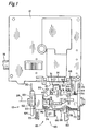
- Fig. 1 is a partial front elevational view of an ink-jet printer illustrating an ink-jet printhead and a service station constructed in accordance with the present invention.
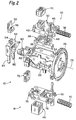
- Fig. 2 is an exploded perspective view of both the black cartridge service station and the color cartridge service station of Fig. 1.
- Fig. 3 is an enlarged perspective view, shown in cross-section, of the color cartridge service station of Figs. 1 and 2.
- Fig. 4 is an elevational section view of the color cartridge service station of Fig. 3.
- Fig. 5 is a view similar to Fig. 4 with the color cartridge cap urged against a printhead.
- a service station for both black cartridge and color cartridge printheads constructed in accordance with the present invention.
- Service station 10 is incorporated into an ink-jet printer into which either a color cartridge or black cartridge may be loaded for color or black ink printing.
- the printer includes a carriage 12 which is shown in the view of Fig. 1 having a black cartridge 14 (shown partially broken away) mounted thereon.
- Cartridge 14 includes a printhead 15 having nozzles (not shown) formed therein for firing ink in the cartridge therefrom.
- Carriage 12 is bidirectionally moveable along a guide rod 16 which substantially spans the width of the printer.
- the carriage is shown in its rightmost position, as viewed in Fig. 1, which places cartridge 14 in service station 10. Carriage 12 moves to the service station when the printer is not printing or when the printhead needs servicing. On other printers the service station may be located at the leftmost side of the printer.
- the printer includes structure for guiding paper through the printer so that the paper surface is positioned immediately beneath printhead 15 when carriage 12 moves leftwardly from service station 10.
- Service station 10 includes a color cartridge service station, indicated generally at 18, and a black cartridge service station, indicated generally at 20.
- Service stations 18, 20 are mounted 180° apart on a rotatable carrier 22.
- Carrier 22 is rotatable 180° about an axis 24. The carrier rotates responsive to a driven gear (not shown) which engages with a sprocket 26 on carrier 22.
- a color cartridge instead of black cartridge 14, is mounted on carriage 12, carrier 22 rotates 180° so that color station 18 is oriented upwardly with black station 20 assuming the position shown for the color station in Fig. 1.
- carrier 22 is in the position illustrated in Fig. 1.
- Black station 20 includes a cap indicated generally at 31.
- the cap includes a basin structure 28, a black sled 30 and a black sled cover 32 all of which are received in a tray 34 formed in carrier 22.
- a spring 36 biases sled 30, as well as sled cover 32 and basin structure 28 which are mounted on the sled, to the left as viewed in Fig. 1.
- Tray 34 includes a pair of opposed cam surfaces, 38, 40 upon which cam followers, like cam followers 42, 44 ride.
- a post 46 presents a leftward-facing surface which engages with an an arm 48 on carriage 12 as the carriage moves to the right.
- spring 36 biases sled 30 to the left.
- Wiper 50 is mounted on a follower bracket 52.
- the follower bracket includes a post 54 which is received in an opening 56 formed in wiper 50.
- a rectangular frame 58 surrounds a cam 60 mounted on carrier 22.
- a pair of downwardly extending posts 62, 64 are received in a pair of corresponding holes (not shown) contained in printer structure (also not shown) beneath carrier 22 in Fig. 1. It can be seen that bracket 52 is maintained in an upper position by cam 60 when carrier 22 is in the position illustrated in Fig. 1. When the carrier rotates 180°, the bracket moves to a lower position as cam 60 rotates from under the bracket.
- Color station 18 includes a color cap indicated generally at 65.
- the color cap includes a sled cover 66 and a color sled 68 (which is also referred to herein as a base).
- a spring 70 biases the sled to the left in Fig. 1.
- sled cover 66 is mounted on sled 68.
- carrier 22 is rotated 180° about axis 24 thus directing sled cover 66 in an upward direction.
- cam 60 inverts and drives bracket 52 to its lower position.
- a color wiper 72 which is mounted on carrier 22 is then also directed upwardly.
- a cam surface 74 (in Fig. 1), such being similar to surface 40, is formed on carrier 22.
- Cam followers 76, 78 ride on the surface similar to the manner in which followers 42, 44 ride on surface 40.
- An arm 80 extends from color sled 68 in the same fashion that arm 46 extends from black sled 30.
- color sled cover 66 is molded from ethylene propylene diene monomer (EPDM) having a hardness of 35 Shore A.
- EPDM ethylene propylene diene monomer
- the sled cover includes an upper sealing lip 82 (also referred to herein as sealing means) which is formed on an upper surface of a tubular structure or member 84 having a substantially rectangular cross section, best viewed in Fig. 2.
- member 84 includes an upper opening 86 which is bounded by the inner perimeter of lip 82, and a lower opening 88, also viewable in Fig. 2.
- Tubular member 84 comprises an upper wall 90 and a lower wall 92 which are integrally formed. As can be seen in Figs. 4 and 5, wall 90 is slightly thinner than wall 92.
- a diaphragm 94 is joined to tubular member 94 about an inner perimeter thereof thus sealing that portion of the tubular member bounded by wall 90 from that portion bounded by wall 92.
- the portion of sled cover 66 between diaphragm 94 and lip 84 comprises a chamber 95, such being also referred to herein as a cavity.
- all of sled cover 66 is integrally molded from EPDM having uniform hardness and flexibility. Because diaphragm 94 is thinner than tubular member 84, the diaphragm flexes more easily than the tubular member. Similarly, because upper wall 90 is thinner than lower wall 92 there is slightly more flex in the upper wall relative to the lower wall. In the present embodiment of the invention, upper wall 90 is sufficiently flexible so that a person may apply lateral and downward pressure against upper wall 90 with his or her finger to deform the cap to the extent that the upper wall folds over against the diaphragm. Upper wall 90 is, however, sufficiently rigid that no drooping or sagging of the wall occurs when pressure is not applied thereto.
- sled 68 is made from nylon 6-10 30% GF.
- sled 68 is substantially rigid.
- the sled includes a substantially square recessed groove 96.
- a substantially square portion 98 of the base extends upwardly interior of groove 96.
- Portion 98 is also referred to herein as a vapor-impervious or vapor-diffusion barrier.
- sled cover 66 is mounted on sled 68 via an interference fit between portion 98 and the lower portion of tubular member 84.
- a seal between square portion 98 and lower wall 92 is formed about the circumference of the cap.
- a diaphragm deflection chamber 100 is formed between diaphragm 94 and square portion 98.
- a vent 102 comprises a bore having an upper opening in communication with chamber 100 and a lower opening in communication with the exterior of sled 68. The lower opening of vent 102 is also visible in Fig. 2.
- Sled 68 further includes a lug 104 over which one end of spring 70 (in Figs. 1 and 2) is received.
- the sled further includes a pair of downward extending legs, one of which is leg 106, which act to retain the sled on carrier 22 while permitting lateral and vertical sled movement as previously described.
- carriage 12 has a color cartridge (not shown) mounted thereon rather than black cartridge 14.
- Carrier 22 is rotated 180° about axis 24 thus placing opening 86 in sled cover 66 immediately beneath the line of travel of the color cartridge printhead.
- arm 48 strikes post 80 thus moving color sled 68 to the right as carriage travel continues.
- the cams like cams 76, 78, which support the color sled on the carrier move up cam surface 74.
- This action moves sled cover 66 toward the color printhead.
- sled cover 66 drives into color printhead 108 (in Fig. 5) beneath a nozzle plate 110 bearing the nozzles (not shown) through which the color cartridge ejects ink onto paper in the printer.
- Lip 82 and upper wall 90 are sufficiently flexible to permit sealing against the lower surface of printhead 108 as illustrated in Fig. 5 and to accommodate any difference in manufacturing tolerances between the cap and the printhead.
- the pressure in chamber 95 rises thus causing diaphragm 94 to deflect downwardly as illustrated in Fig. 5. Such deflection is possible because of the highly flexible nature of membrane 94 and because chamber 100 is vented to atmosphere via vent 102.
- Diaphragm 94 provides an effective liquid barrier between chamber 95 and vent 102 thus preventing moisture from clogging vent 102.
- Vent 102 also serves, as mentioned above, to vent between chamber 100 and atmospheric pressure to permit deflection of diaphragm 94 as shown in Fig. 5. Because vapor diffusion through diaphragm 94 is possible, it is advantageous and desireable for vent 102 to be substantially elongate and relatively narrow in diameter thus minimizing diffusion from chamber 100 to atmosphere. So minimizing the diffusion reduces diffusion from chamber 95 to chamber 100 through diaphragm 94 and thereby inhibits ink drying in the nozzles.
- diaphragm 94 serves to prevent large pressure differentials between chamber 95 and the ambient pressure regardless of the effect tending to cause the pressure differential, e.g., pressure differentials brought about as a result of temperature variations or altitude excursions.
- Diaphragm 94 flexes upwardly in the event of an effect tending to reduce pressure in chamber 95 relative to ambient pressure, e.g., when carriage 12 moves leftwardly from a position in Fig. 1 and spring 70 returns color sled 68 to its leftward, lower position.
- pressure in chamber 95 tends to drop relative to ambient pressure with such a tendency being counteracted by upward flexing of diaphragm 94.
Landscapes
- Ink Jet (AREA)
Claims (9)
- Système de calotte (65) pour une utilisation dans une imprimante à jet d'encre du type comportant un chariot d'impression mobile bidirectionnellement (12) supportant une tête d'impression (15) comportant des éjecteurs d'encre sur elle, ledit système de calotte étant fixe suivant la voie de déplacement du chariot d'impression et comprenant :
une calotte (66) comprenant un élément tubulaire (84) qui peut être poussé contre la tête d'impression lorsque ledit chariot est adjacent audit système de calotte ;
une chambre (95) définie dans ladite calotte ;
une ouverture de calotte (86) en communication avec ladite chambre, lesdits éjecteurs étant en communication avec ladite ouverture lorsque ladite calotte est poussée contre ladite tête d'impression ;
un diaphragme (94) dont un côté est exposé à une pression dans ladite chambre et dont l'autre côté est en communication avec une pression extérieure à ladite chambre ;
une barrière sensiblement imperméable à la vapeur (98) formée dans l'extrémité dudit élément tubulaire opposée à l'extrémité définissant ladite ouverture de calotte ; et
un évent allongé (102) dont une extrémité est en communication avec l'espace entre ledit diaphragme et ladite barrière et dont l'autre extrémité est en communication avec l'extérieur de ladite calotte. - Système de calotte selon la revendication 1, dans lequel ledit système de calotte inclut en outre un moyen d'étanchéité (82) entre ladite calotte et ladite tête d'impression lorsque ladite tête d'impression est poussée contre ladite calotte.
- Système de calotte selon la revendication 1 ou 2, dans lequel ledit diaphragme est formé à partir d'un matériau qui est suffisamment flexible pour être dévié en réponse à une augmentation de la pression de chambre provoquée par une poussée de la calotte contre la tête d'impression.
- Système de calotte selon l'une quelconque des revendications précédentes, dans lequel ledit élément tubulaire de calotte (84) présente une section en coupe sensiblement rectangulaire et dans lequel le périmètre dudit diaphragme est en contact de façon étanche avec ledit élément autour de son périmètre interne.
- Système de calotte selon l'une quelconque des revendications précédentes, dans lequel ladite calotte et ledit diaphragme sont formés d'un seul tenant.
- Système de calotte selon l'une quelconque des revendications précédentes, dans lequel la partie de la calotte qui peut être poussée contre la tête d'impression est moins flexible que ledit diaphragme mais est suffisamment flexible pour assurer l'étanchéité entre la calotte et la tête d'impression lorsque ladite calotte est poussée contre la tête d'impression.
- Système de calotte selon l'une quelconque des revendications précédentes, dans lequel ladite barrière imperméable à la vapeur est définie dans une base sensiblement rigide sur laquelle ladite calotte est montée.
- Système de calotte selon l'une quelconque des revendications précédentes, dans lequel ledit élément tubulaire et ladite barrière imperméable à la vapeur sont sensiblement imperméables à une diffusion de vapeur et dans lequel ledit diaphragme est soumis à une certaine diffusion de vapeur.
- Système de calotte selon l'une quelconque des revendications précédentes, dans lequel ledit élément tubulaire comporte une extrémité en contact de façon étanche avec ladite tête d'impression autour de la circonférence desdits éjecteurs lorsque ladite calotte est poussée contre ladite tête d'impression, ladite barrière imperméable à la vapeur est définie dans une base sensiblement rigide et dans lequel ladite autre extrémité dudit élément tubulaire est emmanchée en force sur ladite base.
Applications Claiming Priority (2)
| Application Number | Priority Date | Filing Date | Title |
|---|---|---|---|
| US737943 | 1991-07-29 | ||
| US07/737,943 US5146243A (en) | 1991-07-29 | 1991-07-29 | Diaphragm cap system for ink-jet printers |
Publications (3)
| Publication Number | Publication Date |
|---|---|
| EP0526010A2 EP0526010A2 (fr) | 1993-02-03 |
| EP0526010A3 EP0526010A3 (en) | 1993-05-26 |
| EP0526010B1 true EP0526010B1 (fr) | 1996-10-16 |
Family
ID=24965905
Family Applications (1)
| Application Number | Title | Priority Date | Filing Date |
|---|---|---|---|
| EP92306212A Expired - Lifetime EP0526010B1 (fr) | 1991-07-29 | 1992-07-07 | Système de calotte à membrane pour imprimantes à jet d'encre |
Country Status (4)
| Country | Link |
|---|---|
| US (1) | US5146243A (fr) |
| EP (1) | EP0526010B1 (fr) |
| JP (1) | JP3342511B2 (fr) |
| DE (1) | DE69214549T2 (fr) |
Families Citing this family (67)
| Publication number | Priority date | Publication date | Assignee | Title |
|---|---|---|---|---|
| DE59007404D1 (de) * | 1990-01-09 | 1994-11-10 | Eastman Kodak Co | Saug- und abdeckeinrichtung zum absaugen von tinte aus tintendruckköpfen eines tintendruckwerkes und zum abdecken der tintendruckköpfe. |
| JP3164156B2 (ja) * | 1990-01-09 | 2001-05-08 | イーストマン コダック カンパニー | 清掃及び密封装置を有するインキジェットプリンタ |
| KR0140505B1 (ko) * | 1991-01-31 | 1998-06-01 | 볼프강 마우스, 지그프리트 나스 | 불균일하게 전기 가열되는 벌집형 본체 |
| DE69307053T2 (de) * | 1992-08-26 | 1997-04-17 | Hewlett Packard Co | Abdeckung mit einer federnden Lippe für einen Tintenstrahl-Druckkopf |
| US5455609A (en) * | 1992-09-30 | 1995-10-03 | Hewlett-Packard Company | Printhead servicing station for printers |
| US5587729A (en) * | 1993-05-11 | 1996-12-24 | Hewlett-Packard Company | Rotatable service station for ink-jet printer |
| ATE177995T1 (de) * | 1993-06-25 | 1999-04-15 | Canon Kk | Tintenstrahlaufzeichnungsgerät |
| US5612722A (en) * | 1993-10-26 | 1997-03-18 | Lexmark International, Inc. | Ink jet printhead wiper having side surfaces intersecting a top surface at acute angles to form wiping edges and a slat centered in a bottom surface |
| US5563637A (en) * | 1993-10-26 | 1996-10-08 | Lexmark International, Inc. | Maintenance station for ink jet printhead |
| US5572245A (en) * | 1994-03-10 | 1996-11-05 | Hewlett-Packard Company | Protective cover apparatus for an ink-jet pen |
| US5712668A (en) * | 1994-03-25 | 1998-01-27 | Hewlett-Packard Company | Rotary Multi-ridge capping system for inkjet printheads |
| US5742308A (en) * | 1994-03-30 | 1998-04-21 | Hewlett-Packard Company | Ink jet printer cartridge refilling method and apparatus |
| JP3259748B2 (ja) * | 1994-03-31 | 2002-02-25 | セイコーエプソン株式会社 | インクジェット式記録装置 |
| US5691755A (en) * | 1994-04-18 | 1997-11-25 | Hewlett-Packard Company | Collapsible ink cartridge |
| US5640182A (en) * | 1994-10-24 | 1997-06-17 | Lexmark International, Inc. | Universal ink-jet printhead maintenance station |
| US5661510A (en) * | 1994-11-22 | 1997-08-26 | Lexmark International, Inc. | Ink-jet cartridge venting |
| US5589865A (en) * | 1994-12-14 | 1996-12-31 | Hewlett-Packard Company | Inkjet page-wide-array printhead cleaning method and apparatus |
| US5635965A (en) * | 1995-01-31 | 1997-06-03 | Hewlett-Packard Company | Wet capping system for inkjet printheads |
| US5583548A (en) * | 1995-03-01 | 1996-12-10 | Hewlett-Packard Company | Bi-directional wiper for ink jet printhead and method of operation |
| US5714991A (en) * | 1995-03-03 | 1998-02-03 | Hewlett-Packard Company | Rotary priming system for inkjet printheads |
| US5801725A (en) * | 1995-05-03 | 1998-09-01 | Encad, Inc. | Slidable wiping and capping service station for ink jet printer |
| US5757395A (en) * | 1995-09-25 | 1998-05-26 | Hewlett-Packard Company | Color capable single-cartridge inkjet service station |
| US5956053A (en) * | 1996-10-31 | 1999-09-21 | Hewlett-Packard Company | Dual seal capping system for inkjet printheads |
| US5936647A (en) * | 1996-10-31 | 1999-08-10 | Hewlett-Packard Company | Flexible frame onsert capping of inkjet printheads |
| JP4022946B2 (ja) * | 1996-11-15 | 2007-12-19 | ブラザー工業株式会社 | キャッピング装置 |
| JP2878214B2 (ja) * | 1996-11-20 | 1999-04-05 | 新潟日本電気株式会社 | インクジェット記録装置 |
| US7037382B2 (en) | 1996-12-20 | 2006-05-02 | Z Corporation | Three-dimensional printer |
| US6007318A (en) | 1996-12-20 | 1999-12-28 | Z Corporation | Method and apparatus for prototyping a three-dimensional object |
| KR100229508B1 (ko) * | 1997-04-22 | 1999-11-15 | 윤종용 | 잉크 카트리지를 감지하여 데이터를 만드는 원도우즈 드라이버 |
| US6493937B1 (en) | 1998-03-16 | 2002-12-17 | Hewlett-Packard Company | Method of manufacture for ink-jet hard copy apparatus using a modular approach to ink-jet technology |
| US6082854A (en) | 1998-03-16 | 2000-07-04 | Hewlett-Packard Company | Modular ink-jet hard copy apparatus and methodology |
| US6406123B1 (en) | 1998-09-07 | 2002-06-18 | Seiko Epson Corporation | Capping unit for ink jet recording head incorporated in ink jet recording apparatus and method of manufacturing the same |
| US6224186B1 (en) | 1999-01-08 | 2001-05-01 | Hewlett-Packard Company | Replaceable inkjet ink solvent application system |
| US6155667A (en) | 1999-01-08 | 2000-12-05 | Hewlett-Packard Company | Replaceable snout wiper for inkjet cartridges |
| JP2000203040A (ja) | 1999-01-08 | 2000-07-25 | Hewlett Packard Co <Hp> | プリントヘッド・クリ―ニング・システム |
| US6520621B1 (en) | 1999-01-08 | 2003-02-18 | Hewlett-Packard Company | Dual wiper scrapers for incompatible inkjet ink wipers |
| US6135585A (en) | 1999-01-08 | 2000-10-24 | Hewlett-Packard Company | Replaceable capping system for inkjet printheads |
| US6283576B1 (en) | 1999-10-29 | 2001-09-04 | Xerox Corporation | Ventable ink jet printhead capping and priming assembly |
| US6406124B1 (en) * | 2000-01-31 | 2002-06-18 | Hewlett-Packard Company | Ganged inkjet printhead capping system |
| US6304728B1 (en) | 2000-03-14 | 2001-10-16 | Concord Camera Corp. | Camera with flash unit disposed in between viewfinder lenses |
| US6382766B1 (en) * | 2000-04-20 | 2002-05-07 | Samsung Electronics Co., Ltd. | Maintenance apparatus for ink nozzle of image forming apparatus |
| US6378980B1 (en) | 2000-05-18 | 2002-04-30 | Samsung Electronics Co., Ltd. | Printer capable of preventing drying of nozzle and control method thereof |
| US6412905B1 (en) * | 2000-12-21 | 2002-07-02 | Acer Communications And Multimedia | Ink jet cap with vent |
| US6623098B2 (en) | 2001-10-31 | 2003-09-23 | Hewlett-Packard Company, L.P. | Positive stop capping system for inkjet printheads |
| US6609779B2 (en) | 2001-10-31 | 2003-08-26 | Hewlett-Packard Development Company, L.P. | Bellows capping system for inkjet printheads |
| US6742860B2 (en) | 2002-01-18 | 2004-06-01 | Hewlett-Packard Development Company, L.P. | Apparatus and method for capping one or more printheads in a printing device |
| US6962408B2 (en) | 2002-01-30 | 2005-11-08 | Hewlett-Packard Development Company, L.P. | Printing-fluid container |
| US7744202B2 (en) * | 2002-01-30 | 2010-06-29 | Hewlett-Packard Development Company, L.P. | Printing-fluid container |
| US7147310B2 (en) * | 2002-01-30 | 2006-12-12 | Hewlett-Packard Development Company, L.P. | Printing-fluid container |
| US6648460B2 (en) | 2002-01-30 | 2003-11-18 | Hewlett-Packard Development Company, L.P. | High volumetric efficiency ink container vessel |
| US6733106B1 (en) * | 2002-10-24 | 2004-05-11 | Lexmark International, Inc. | Ink jet maintenance station with radial orientation |
| US6877849B2 (en) * | 2003-01-23 | 2005-04-12 | Hewlett-Packard Development Company, L.P. | Printing system with high volumetric ink container vessel |
| US6851787B2 (en) * | 2003-03-06 | 2005-02-08 | Hewlett-Packard Development Company, L.P. | Printer servicing system and method |
| US6932455B2 (en) * | 2003-04-30 | 2005-08-23 | Hewlett-Packard Development Company, L.P. | Printing apparatus and method |
| JP2007503342A (ja) | 2003-05-23 | 2007-02-22 | ズィー コーポレイション | 三次元プリント装置及び方法 |
| US7104630B2 (en) * | 2003-07-31 | 2006-09-12 | Hewlett-Packard Development Company, L.P. | Printing-fluid container |
| US7004564B2 (en) | 2003-07-31 | 2006-02-28 | Hewlett-Packard Development Company, L.P. | Printing-fluid container |
| US6959985B2 (en) * | 2003-07-31 | 2005-11-01 | Hewlett-Packard Development Company, L.P. | Printing-fluid container |
| WO2005097476A2 (fr) * | 2004-04-02 | 2005-10-20 | Z Corporation | Procedes et appareil d’impression en trois dimensions |
| US7387359B2 (en) * | 2004-09-21 | 2008-06-17 | Z Corporation | Apparatus and methods for servicing 3D printers |
| US7311376B2 (en) * | 2004-09-22 | 2007-12-25 | Hewlett-Packard Development Company, L.P. | Imaging device and method |
| US7159964B2 (en) * | 2004-09-30 | 2007-01-09 | Lexmark International, Inc. | Inkjet printer spit cup assembly |
| JP2007268852A (ja) * | 2006-03-31 | 2007-10-18 | Brother Ind Ltd | インクジェット記録装置及びキャップ |
| US7828022B2 (en) | 2006-05-26 | 2010-11-09 | Z Corporation | Apparatus and methods for handling materials in a 3-D printer |
| US20100253738A1 (en) * | 2009-04-03 | 2010-10-07 | Keith Jariabka | Carriage-actuated vent system for inkjet print heads |
| US9266336B1 (en) | 2015-04-07 | 2016-02-23 | Xerox Corporation | Ink barrier formed on printhead to prevent air intake |
| JP7087303B2 (ja) * | 2017-08-24 | 2022-06-21 | セイコーエプソン株式会社 | キャップ装置及び液体噴射装置 |
Family Cites Families (12)
| Publication number | Priority date | Publication date | Assignee | Title |
|---|---|---|---|---|
| DE3041187A1 (de) * | 1980-11-03 | 1982-06-03 | Philips Patentverwaltung Gmbh, 2000 Hamburg | Vorrichtung zum elastischen abdecken der duesen eines tintenschreibkopfes |
| AT377726B (de) * | 1981-07-24 | 1985-04-25 | Philips Nv | Kassette mit einer einrichtung zum abdecken und/oder einer einrichtung zum reinigen der duesenflaeche eines schreibkopfes eines tintenstrahlschreibers |
| JPS5945164A (ja) * | 1982-09-08 | 1984-03-13 | Seiko Epson Corp | インクジエツトプリンタのノズルキヤツプ |
| US4511906A (en) * | 1982-10-13 | 1985-04-16 | Sharp Kabushiki Kaisha | Ink liquid reservoir in an ink jet system printer |
| GB2131745B (en) * | 1982-10-14 | 1986-06-25 | Epson Corp | Ink jet head assembly |
| JPH0684081B2 (ja) * | 1983-09-29 | 1994-10-26 | キヤノン株式会社 | 吐出回復方法 |
| US4684963A (en) * | 1984-06-08 | 1987-08-04 | Seiko Epson Kabushiki Kaisha | Nozzle cover assembly for an ink-on-demand type ink jet printer |
| DE3432620A1 (de) * | 1984-09-05 | 1986-03-13 | Agfa-Gevaert Ag, 5090 Leverkusen | Deckel fuer die duesen eines unterdrucktintendruckkopfes |
| JP2522770B2 (ja) * | 1986-08-05 | 1996-08-07 | キヤノン株式会社 | インクジェット装置 |
| JPS6485769A (en) * | 1987-09-28 | 1989-03-30 | Toshiba Corp | Recorder |
| US4853717A (en) * | 1987-10-23 | 1989-08-01 | Hewlett-Packard Company | Service station for ink-jet printer |
| US5027134A (en) * | 1989-09-01 | 1991-06-25 | Hewlett-Packard Company | Non-clogging cap and service station for ink-jet printheads |
-
1991
- 1991-07-29 US US07/737,943 patent/US5146243A/en not_active Expired - Lifetime
-
1992
- 1992-07-07 EP EP92306212A patent/EP0526010B1/fr not_active Expired - Lifetime
- 1992-07-07 DE DE69214549T patent/DE69214549T2/de not_active Expired - Fee Related
- 1992-07-22 JP JP21636892A patent/JP3342511B2/ja not_active Expired - Fee Related
Also Published As
| Publication number | Publication date |
|---|---|
| DE69214549D1 (de) | 1996-11-21 |
| JPH05201007A (ja) | 1993-08-10 |
| EP0526010A2 (fr) | 1993-02-03 |
| EP0526010A3 (en) | 1993-05-26 |
| US5146243A (en) | 1992-09-08 |
| JP3342511B2 (ja) | 2002-11-11 |
| DE69214549T2 (de) | 1997-03-06 |
Similar Documents
| Publication | Publication Date | Title |
|---|---|---|
| EP0526010B1 (fr) | Système de calotte à membrane pour imprimantes à jet d'encre | |
| US5216449A (en) | Rounded capillary vent system for ink-jet printers | |
| US5757395A (en) | Color capable single-cartridge inkjet service station | |
| EP0313204B1 (fr) | Poste de maintenance pour imprimante à jet d'encre | |
| US5027134A (en) | Non-clogging cap and service station for ink-jet printheads | |
| US6174041B1 (en) | Modular printhead service station with self-contained motorized components | |
| EP0622201B1 (fr) | Appareil d'amorçage pour imprimante par jet d'encre | |
| EP0901905B1 (fr) | Dispositif de recouvrement pour une tête d'impression à jet d'encre | |
| US6074037A (en) | Print head capping device | |
| US7527349B2 (en) | Inkjet image forming apparatus and method of maintaining nozzle unit thereof | |
| JP3676792B2 (ja) | インクペンアセンブリ。 | |
| EP0720912B1 (fr) | Dispositif d'entretien dans un appareil d'impression à jet d'encre | |
| JP3091485B2 (ja) | インキジェットプリンタのプリンタヘッドからインキを吸出すためとプリンタヘッドを被覆するための吸込み及び被覆装置 | |
| EP2197682B1 (fr) | Citerne à liquides avec mécanisme de mise à l'air libre | |
| US7806506B2 (en) | Droplet ejecting device having cap that seals nozzles | |
| US4571600A (en) | Nozzle blockage preventing unit in an ink jet system printer | |
| EP0720913B1 (fr) | Dispositif d'entretien dans un appareil d'impression à jet d'encre | |
| US7806507B2 (en) | Liquid ejection apparatus, capping device, and installation device for liquid absorber | |
| US6817695B1 (en) | Printhead capping assembly | |
| JPH05508358A (ja) | 清掃及び密封装置を有するインキジェットプリンタ | |
| US7021741B2 (en) | Printhead cap assembly for an ink jet printer | |
| US20030020782A1 (en) | Method for increasing waste ink collection capacity in an ink jet printer by utilizing multiple ink spit areas along the carrier path | |
| US6709087B2 (en) | Printing device | |
| US7552994B2 (en) | Print-head maintenance device for use in an inkjet printer | |
| JP3765361B2 (ja) | インクジェット式記録装置 |
Legal Events
| Date | Code | Title | Description |
|---|---|---|---|
| PUAI | Public reference made under article 153(3) epc to a published international application that has entered the european phase |
Free format text: ORIGINAL CODE: 0009012 |
|
| AK | Designated contracting states |
Kind code of ref document: A2 Designated state(s): DE FR GB IT |
|
| PUAL | Search report despatched |
Free format text: ORIGINAL CODE: 0009013 |
|
| RIN1 | Information on inventor provided before grant (corrected) |
Inventor name: WARD, JEFFERSON P Inventor name: HARMON, J.P. Inventor name: ENGLISH, KRIS M. |
|
| AK | Designated contracting states |
Kind code of ref document: A3 Designated state(s): DE FR GB IT |
|
| 17P | Request for examination filed |
Effective date: 19931103 |
|
| 17Q | First examination report despatched |
Effective date: 19950210 |
|
| GRAH | Despatch of communication of intention to grant a patent |
Free format text: ORIGINAL CODE: EPIDOS IGRA |
|
| ITF | It: translation for a ep patent filed | ||
| GRAA | (expected) grant |
Free format text: ORIGINAL CODE: 0009210 |
|
| AK | Designated contracting states |
Kind code of ref document: B1 Designated state(s): DE FR GB IT |
|
| REF | Corresponds to: |
Ref document number: 69214549 Country of ref document: DE Date of ref document: 19961121 |
|
| ET | Fr: translation filed | ||
| PLBE | No opposition filed within time limit |
Free format text: ORIGINAL CODE: 0009261 |
|
| STAA | Information on the status of an ep patent application or granted ep patent |
Free format text: STATUS: NO OPPOSITION FILED WITHIN TIME LIMIT |
|
| 26N | No opposition filed | ||
| REG | Reference to a national code |
Ref country code: GB Ref legal event code: 732E |
|
| REG | Reference to a national code |
Ref country code: FR Ref legal event code: TP |
|
| REG | Reference to a national code |
Ref country code: GB Ref legal event code: IF02 |
|
| PGFP | Annual fee paid to national office [announced via postgrant information from national office to epo] |
Ref country code: FR Payment date: 20050718 Year of fee payment: 14 |
|
| REG | Reference to a national code |
Ref country code: FR Ref legal event code: ST Effective date: 20070330 |
|
| PGFP | Annual fee paid to national office [announced via postgrant information from national office to epo] |
Ref country code: DE Payment date: 20070831 Year of fee payment: 16 |
|
| PGFP | Annual fee paid to national office [announced via postgrant information from national office to epo] |
Ref country code: IT Payment date: 20070730 Year of fee payment: 16 |
|
| PG25 | Lapsed in a contracting state [announced via postgrant information from national office to epo] |
Ref country code: FR Free format text: LAPSE BECAUSE OF NON-PAYMENT OF DUE FEES Effective date: 20060731 |
|
| PG25 | Lapsed in a contracting state [announced via postgrant information from national office to epo] |
Ref country code: DE Free format text: LAPSE BECAUSE OF NON-PAYMENT OF DUE FEES Effective date: 20090203 |
|
| PG25 | Lapsed in a contracting state [announced via postgrant information from national office to epo] |
Ref country code: IT Free format text: LAPSE BECAUSE OF NON-PAYMENT OF DUE FEES Effective date: 20080707 |
|
| PGFP | Annual fee paid to national office [announced via postgrant information from national office to epo] |
Ref country code: GB Payment date: 20110725 Year of fee payment: 20 |
|
| REG | Reference to a national code |
Ref country code: GB Ref legal event code: 732E Free format text: REGISTERED BETWEEN 20120329 AND 20120404 |
|
| REG | Reference to a national code |
Ref country code: GB Ref legal event code: PE20 Expiry date: 20120706 |
|
| PG25 | Lapsed in a contracting state [announced via postgrant information from national office to epo] |
Ref country code: GB Free format text: LAPSE BECAUSE OF EXPIRATION OF PROTECTION Effective date: 20120706 |