EP0526049A2 - Dispositif d'alimentation de pièces de monnaie - Google Patents
Dispositif d'alimentation de pièces de monnaie Download PDFInfo
- Publication number
- EP0526049A2 EP0526049A2 EP92306518A EP92306518A EP0526049A2 EP 0526049 A2 EP0526049 A2 EP 0526049A2 EP 92306518 A EP92306518 A EP 92306518A EP 92306518 A EP92306518 A EP 92306518A EP 0526049 A2 EP0526049 A2 EP 0526049A2
- Authority
- EP
- European Patent Office
- Prior art keywords
- coin
- belt
- front surface
- rotary plate
- transporting piece
- Prior art date
- Legal status (The legal status is an assumption and is not a legal conclusion. Google has not performed a legal analysis and makes no representation as to the accuracy of the status listed.)
- Granted
Links
Images


Classifications
-
- G—PHYSICS
- G07—CHECKING-DEVICES
- G07D—HANDLING OF COINS OR VALUABLE PAPERS, e.g. TESTING, SORTING BY DENOMINATIONS, COUNTING, DISPENSING, CHANGING OR DEPOSITING
- G07D1/00—Coin dispensers
-
- G—PHYSICS
- G07—CHECKING-DEVICES
- G07D—HANDLING OF COINS OR VALUABLE PAPERS, e.g. TESTING, SORTING BY DENOMINATIONS, COUNTING, DISPENSING, CHANGING OR DEPOSITING
- G07D9/00—Counting coins; Handling of coins not provided for in the other groups of this subclass
- G07D9/008—Feeding coins from bulk
Definitions
- This invention relates to a coin feeding device, for use in coin exchangers, coin operated gaming machines or the like, which feeds predetermined number of coins one by one held in a hopper in bulk.
- Such a coin feeding device comprises a hopper for holding a supply of coins or tokens in bulk.
- a rotary disc is rotatably disposed and is provided with a central circular stage.
- a plurality of coin transporting pins are provided with a carrier. The pins are protruded in a peripheral portion around the central circular stage and spaced apart in the peripheral direction of the rotary disc.
- a coin delivery guide is extended across the peripheral portion of the rotary disc for guiding coins on the peripheral portion to an outlet chute.
- the carrier having a plurality of coin transporting pins spaced apart in the circumferential direction is rotatably supported at the rear side of the rotary disc.
- the carrier is rotated at an angle to the rotary disc such as to extrude the pins extended through the rotary disc from the surface of the peripheral portion of the rotary disc in a minimum amount at a position of the delivery guide and in a maximum amount at a coin picking up position.
- such structure allows the coin feeding device to improve the function of picking up coins from the bottom portion of the hopper by means of a long transporting pin. In this event, coins are transported without jamming in the upper delivery portion.
- this device it is possible for this device to improve a coin dispensing efficiency by providing means for agitating coins in the lower portion of the hopper. In other words, it is possible to increase the number of coins transported per second.
- the coin feeding device disclosed in the above mentioned U.S. Patent there is no problem of interference between the outlet chute and the coin transporting pins.
- a coin sorting device where the rotary disc is rotated at a high speed.
- the coins are radially outwardly transported on the rotary disc with effectively utilizing the centrifugal force. More particularly, the coins are guided to the outlet chute by means of a peripheral guide member, an outlet guide member or the like arranged at the peripheral portion of the rotary disc.
- a large dish-like hopper is generally used in order to smoothly supply an adequate number of coins.
- a rotary disc having large diameter to prevent the coins flying away of the disc. This results in the device being enlarged.
- an object of the present invention is to provide a coin feeding device where coin feeding efficiency can be improved by increasing the rotation speed of the coin feeding disc without enlarging the device.
- the invention provides a coin sorting device comprising a rotary plate having a surface to which a coin is loaded at a first portion thereof and fed to a coin outlet located at the periphery of said surface; means cooperating with said plate to engage said coin at the first portion of the surface and for disengaging from said coin at a second portion of the surface angularly spaced from the first portion, said device being characterised by a coin feeding belt means for feeding said coin to said coin outlet from the second portion of said plate; said coin feeding belt means comprising a belt member extending from the second portion of said surface to said coin outlet in such a manner that said coin is in contact with a portion thereof; and a belt driving member for driving said belt portion in the same direction as said rotary plate.
- a coin feeding device comprises a rotary plate having a front surface on one side where a coin is loaded at a lower portion thereof and a rear surface on the other side, said rotary plate is for use in feeding said coin to a coin outlet located at or around a periphery of said front surface; a coin transporting piece receiving hole which is penetrating through said rotary plate; a coin transporting piece carrier which is rotated in synchronism with said rotary plate in an opposed position inclined to said rear surface of said rotary plate at a predetermined inclination angle; and a coin transporting piece protruded from said coin transporting piece carrier, said coin transporting piece projects from said front surface passing through said coin transporting piece receiving hole, wherein said coin transporting piece catches said coin at a lower portion of said front surface and feeds it to an upper portion of said front surface, and said predetermined inclination angle is in the range such that said coin transporting piece is substantially extended from said front surface as said coin transporting piece approaches the lower portion from
- the coin feeding belt means comprises a belt driving pulley and two guide pulleys, which are arranged at the vertexes, respectively, of a triangle extending on a plane of the coin feeding disc; and an endless belt passing around these pulleys, wherein the coin feeding belt portion is extended between both guide pulleys and the belt driving pulley is driven in a peripheral portion of the coin feeding disc with frictionally contacting therewith.
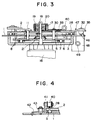
- an illustrated coin feeding device comprises an inclined base plate 1.
- the inclined base plate 1 is secured on a fixed supporting frame (not shown).
- the inclined base plate 1 is secured in a position inclined to the horizontal at a predetermined angle. In this embodiment, the angle between the inclined base plate 1 and the horizontal is 60 degrees.
- a coin feeding disc 2 is rotatably supported on the inclined base plate 1 at a peripheral portion thereof.
- the coin feeding disc 2 is supported by means of a circular thrust bearing 3.
- Such circular thrust bearing 3 is disclosed in, for example, Japanese Patent Examined Publication No. Tokko-hei 3-9512.
- the coin feeding disc 2 has a front surface on one side and a rear surface on the other side.
- a coin is loaded at a lower portion of the front surface and transported to a coin outlet located at or around a periphery of the front surface.
- the coin feeding device also comprises a hopper 4 for holding a supply of coins in bulk.
- the hopper 4 is mounted in such a manner that it surrounds the lower portion of the coin feeding disc 2.
- a carrier supporting disc 6 is fixed to the rear surface of the inclined base plate 1. Between an inner surface of the carrier supporting disc 6 and the rear surface of the coin feeding disc 2, a coin transporting piece carrier 5 is rotatably supported. The coin transporting piece carrier 5 is rotated in synchronism with the coin feeding disc in a manner as described below.
- the coin transporting piece carrier 5 is inclined to the rear surface of the coin feeding disc 2 at a predetermined angle. In the illustrated embodiment, the coin transporting piece carrier 5 is inclined to the inclined base plate 1 at an angle of 5 degrees.
- a circular thrust bearing 7 is provided with the carrier supporting disc for supporting the coin transporting piece carrier 5 in the same manner as described in the above mentioned U.S. Patent No. 5,000,718.
- the circular thrust bearing 7 is similar to the circular thrust bearing 3.
- a plurality of cylindrical coin transporting pieces 8 are protruded from the coin transporting piece carrier 5 at the peripheral portion thereof. Each of the coin transporting pieces 8 is protruded from the coin transporting piece carrier 5 towards the coin feeding disc 2. The coin transporting pieces 8 are equally spaced apart from each other in the circumferential direction of the coin transporting piece carrier 5.
- First coin transporting piece receiving holes 9 are provided with the inclined base plate 1. Each of the first coin transporting piece receiving holes 9 penetrates the inclined base plate 1.
- second coin transporting piece receiving holes 10 are provided with the coin feeding disc 2. Each of the second coin transporting piece receiving holes 10 penetrates the coin feeding disc 2. Both of the fist and second coin transporting piece receiving holes 9 and 10 are equal in number to the coin transporting pieces 8.
- the coin transporting pieces 8 project from the front surface passing through their respective coin transporting piece receiving holes 9 and 10.
- a plurality of cylindrical coin agitating members 11 are protruded towards the coin feeding disc 2.
- the coin agitating members 11 are equally spaced apart with each other in the circumferential direction of the coin transporting piece carrier 5.
- Coin agitating member receiving holes 13, 14 and 15 are provided with the inclined base plate 1, the coin feeding disc 2 and a central stage 12, respectively.
- the coin agitating member receiving holes 13 are equal in number to the coin agitating members 11.
- both the coin agitating member receiving holes 14 and 15 are equal in number to the coin agitating member 11.
- the coin agitating members 11 pass through their respective coin agitating member receiving holes 13, 14, and 15.
- a rotating shaft 17 is driven through a built-in reduction gear (not shown) by means of a motor 16.
- the motor 16 is supported on the carrier supporting disc 6.
- the rotating shaft 17 is extended through the carrier supporting disc 6, the coin transporting piece carrier 5, the inclined base plate 1 and the coin feeding disc 2.
- a cap 19 is fixed to the top of the rotating shaft 17 by means of a screw 18.
- a first biasing member 20 is interposed between the coin feeding disc 2 and the cap 19.
- a second biasing member 21 is interposed between the inclined base plate 1 and the coin transporting piece carrier 5.
- both of the first and second biasing members are in the form of springs.
- the central portion of the coin feeding disc 2 is urged towards the inclined base plate 1 to rotatably support the coin feeding disc 2 on the inclined base plate 1 through the thrust bearing 3.
- the central portion of the inclined base plate 1 is urged towards the carrier supporting disc 6 to rotatably support the inclined base plate 1 on the carrier supporting disc 6 through the thrust bearing 7.
- the coin feeding disc 2 and the coin transporting piece carrier 5 are drivingly connected with each other in a well known manner. Accordingly, they are rotated in synchronism with each other with the rotating shaft 17. More particularly, when the coin feeding disc 2 is rotated by the rotating shaft 17, the coin transporting piece carrier 5 is synchronously rotated with the coin feeding disc 2. As mentioned above, the coin transporting piece carrier 5 is inclined to the coin feeding disc 2 at an angle such that the protrusion amount of the coin transporting pieces 8 is substantially equal to zero at a coin outlet portion 25. At this coin outlet portion 25, the protrusion amount of the coin agitating members 11 is substantially minimum.
- each of the coin transporting pieces 8 and the coin agitating members 11 protrudes into the hopper 4 in a maximum amount. Accordingly, it is possible to effectively pick up coins in the hopper 4 as well as to improve coin agitating efficiency.
- a coin feeding belt arrangement is provided near the coin outlet portion 25 for feeding the coins to the coin outlet portion 25 on the front surface of the coin feeding disc 2.
- the coin feeding belt arrangement comprises a coin feeding belt 28 and a belt driving member.
- the coin feeding belt 28 is an endless belt.
- the coin feeding belt 28 extends from the upper portion of the front surface of the coin feeding disc 2 to the coin outlet portion 25.
- Each of the coins is to be guided to the coin outlet portion 25 in a contact relation with the coin feeding belt 28.
- the coin feeding belt comprises a coin feeding belt portion 28a.
- the coin feeding belt portion 28a directly extends, on a plane including the front surface of the coin feeding disc 2.
- a guiding peripheral wall portion 27 is provided in somewhat short of a coin outlet 26 with respect to the rotation direction of the coin feeding disc 2.
- the coin feeding belt portion 28a extends from the guiding peripheral wall portion 27 to the coin outlet 26.
- the coin feeding belt 28 moves in a rotation direction of the coin feeding disc 2 in a manner described below.
- the belt driving member comprises a belt driving pulley 33.
- the belt driving pulley 33 is rotatably supported by a shaft 30.
- the belt driving pulley 33 is rotated by means of the coin feeding disc 2 in a frictionally well-contact relation therewith. More particularly, the belt driving pulley 33 is frictionally contact with a peripheral surface of the coin feeding disc 2.
- the belt driving member also comprises two guide pulleys 34 and 35. Each of the guide pulleys 34 and 35 is rotatably supported by shaft 31 and 32, respectively. As illustrated in Fig. 1, centers of the three shafts 30, 31 and 32 are located at points A, B and C, respectively.
- Each of the points A, B and C corresponds to each vertex of a triangle extending on a plane including the surface of the coin feeding disc 2.
- Each shaft is disposed integrally to the inclined base plate 1 and the endless coin feeding belt 28 is passed around these pulleys.
- the coin feeding belt portion 28a is extended between both guide pulleys 34 and 35.
- the coin feeding belt portion 28a moves between the two guide pulleys 34 and 35 to transport the coin to the coin outlet 26.
- the shaft 30 of the driving pulley 33 is attached to a lever 37.
- One end of the lever 37 is pivotally attached to the inclined base plate 1 by means of a pivot pin 36.
- the other end of the lever 37 is connected to the inclined base plate 1 through a biasing member in the form of a spring 38.
- the belt driving pulley 33 is forced towards a peripheral surface of the coin feeding disc 2 due to a spring force of the spring 38.
- the belt driving pulley 33 allows to be frictionally contact with a peripheral flange 2a of the coin feeding disc 2.
- the coin feeding belt 28 is driven by the coin feeding disc 2 through the belt driving pulley 33.
- the coin feeding belt arrangement comprises a belt presser roller 40.
- the belt presser roller 40 is rotatably supported by a roller shaft 41.
- the roller shaft 41 is secured on a supporting plate 42.
- a spring 43 is provided on the surface of the supporting plate 42 by means of a screw. Due to the spring force of the spring 43, the belt presser roller 40 allows to press the coin feeding belt portion 28 towards the front surface of the coin feeding disc 2.
- the coin is securely transported to the coin outlet 26 in contact relation with the endless belt 28 without being adversely affected by the centrifugal force.
- a coin counting sensor 46 is provided on the surface of the inclined base plate 1 at a coin outlet chute.
- An outlet gate 47 is attached to a movable member 49 of a electromagnet 48.
- the electromagnet 48 is weakened and the gate 47 is moved by means of a spring to the illustrated coin shutdown position to close the coin outlet.
- the coin feeding disc 2 is rotated at a relatively high speed in a hopper in a position inclined to the horizontal.
- the coin transporting pieces 8 pick up the coin one by one. Then the picked up coin is transported along the peripheral wall with utilizing the centrifugal force which acts to the coin feeding disc 2.
- the hopper 4 is no more required to be formed like a dish having a large surface area. The smaller hopper can be used which is deep for holding a large number of coins. Further, it is unnecessary to prepare a coin feeding disc 2 having large diameter.
- the coin feeding pieces 8 are not protruded from the surface of the coin feeding disc 2 at the coin outlet portion 25. Accordingly, it is possible to securely and smoothly feed the coins to the coin outlet 26 using the coin feeding belt 28 with effectively utilizing the centrifugal force.
Landscapes
- Physics & Mathematics (AREA)
- General Physics & Mathematics (AREA)
- Pinball Game Machines (AREA)
- Filling Or Emptying Of Bunkers, Hoppers, And Tanks (AREA)
- Attitude Control For Articles On Conveyors (AREA)
- Feeding Of Articles To Conveyors (AREA)
- Slot Machines And Peripheral Devices (AREA)
Applications Claiming Priority (2)
| Application Number | Priority Date | Filing Date | Title |
|---|---|---|---|
| JP3269963A JPH0528340A (ja) | 1991-07-19 | 1991-07-19 | コイン送出装置 |
| JP269963/91 | 1991-07-19 |
Publications (3)
| Publication Number | Publication Date |
|---|---|
| EP0526049A2 true EP0526049A2 (fr) | 1993-02-03 |
| EP0526049A3 EP0526049A3 (fr) | 1994-04-06 |
| EP0526049B1 EP0526049B1 (fr) | 1995-12-27 |
Family
ID=17479664
Family Applications (1)
| Application Number | Title | Priority Date | Filing Date |
|---|---|---|---|
| EP92306518A Expired - Lifetime EP0526049B1 (fr) | 1991-07-19 | 1992-07-16 | Dispositif d'alimentation de pièces de monnaie |
Country Status (6)
| Country | Link |
|---|---|
| US (1) | US5254032A (fr) |
| EP (1) | EP0526049B1 (fr) |
| JP (1) | JPH0528340A (fr) |
| KR (1) | KR950014079B1 (fr) |
| AU (1) | AU656599B2 (fr) |
| ES (1) | ES2081571T3 (fr) |
Cited By (3)
| Publication number | Priority date | Publication date | Assignee | Title |
|---|---|---|---|---|
| EP0896302A1 (fr) * | 1997-08-06 | 1999-02-10 | Universal Sales Co., Ltd. | Elévateur pour pièces de monnaie |
| EP1037174A4 (fr) * | 1998-06-15 | 2004-09-15 | Sugai General Ind Ltd | Dispositif permettant de compter des pieces de monnaie ou analogue |
| WO2019063049A1 (fr) * | 2017-09-27 | 2019-04-04 | Ctcoin A/S | Mécanisme de séparation de pièces de monnaie et appareil de traitement de pièces de monnaie comportant un tel mécanisme |
Families Citing this family (14)
| Publication number | Priority date | Publication date | Assignee | Title |
|---|---|---|---|---|
| US5616074A (en) * | 1996-04-29 | 1997-04-01 | Chen; Chin-Nan | Apparatus for counting coins |
| US5988348A (en) | 1996-06-28 | 1999-11-23 | Coinstar, Inc. | Coin discrimination apparatus and method |
| US6520308B1 (en) | 1996-06-28 | 2003-02-18 | Coinstar, Inc. | Coin discrimination apparatus and method |
| US6196371B1 (en) | 1996-06-28 | 2001-03-06 | Coinstar, Inc. | Coin discrimination apparatus and method |
| US5688166A (en) * | 1996-07-10 | 1997-11-18 | Chen; Chih-Nan | Apparatus for counting coins |
| US6168001B1 (en) | 1997-06-27 | 2001-01-02 | Coinstar, Inc. | Positive drive coin discrimination apparatus and method |
| US7152727B2 (en) | 2001-09-21 | 2006-12-26 | Coinstar, Inc. | Method and apparatus for coin or object sensing using adaptive operating point control |
| US6786814B2 (en) * | 2002-11-27 | 2004-09-07 | Chen Chih-Nan | Coin counting device |
| JP4810691B2 (ja) * | 2003-12-12 | 2011-11-09 | 旭精工株式会社 | コインホッパー |
| JP4515361B2 (ja) * | 2005-09-05 | 2010-07-28 | 株式会社オリンピア | ホッパー装置 |
| US9036890B2 (en) | 2012-06-05 | 2015-05-19 | Outerwall Inc. | Optical coin discrimination systems and methods for use with consumer-operated kiosks and the like |
| US8967361B2 (en) | 2013-02-27 | 2015-03-03 | Outerwall Inc. | Coin counting and sorting machines |
| US9022841B2 (en) | 2013-05-08 | 2015-05-05 | Outerwall Inc. | Coin counting and/or sorting machines and associated systems and methods |
| US9443367B2 (en) | 2014-01-17 | 2016-09-13 | Outerwall Inc. | Digital image coin discrimination for use with consumer-operated kiosks and the like |
Family Cites Families (9)
| Publication number | Priority date | Publication date | Assignee | Title |
|---|---|---|---|---|
| SE359669B (fr) * | 1971-05-28 | 1973-09-03 | Scan Coin Ab | |
| DE2510230A1 (de) * | 1975-03-08 | 1976-09-16 | Franz Otto Altenbach | Vorrichtung zum zaehlen und sortieren von muenzen verschiedener groesse |
| JPS5937661B2 (ja) * | 1977-05-25 | 1984-09-11 | 松下電工株式会社 | コアレスモ−タ−の回転子 |
| US4589433A (en) * | 1983-12-07 | 1986-05-20 | Asahi Seiko Kabushiki Kaisha | Coin dispensing apparatus |
| DE3419589C1 (de) * | 1984-05-22 | 1986-01-02 | F. Zimmermann & Co, 1000 Berlin | Vorrichtung zum Sortieren und Zaehlen von Muenzen eines Muenzenkollektives |
| EP0293608B1 (fr) * | 1987-06-03 | 1994-09-14 | Rudolf Stöckli | Dispositif pour séparer des objets en forme de disque, en particulier des pièces de monnaie |
| JPS6446894A (en) * | 1987-08-17 | 1989-02-21 | Ace Denken Kk | Coin feeder |
| US5000718A (en) * | 1988-06-04 | 1991-03-19 | Asahi Seiko Kabushiki Kaisha | Coin dispensing apparatus |
| JPH0797420B2 (ja) * | 1988-06-04 | 1995-10-18 | 旭精工株式会社 | 硬貨送出装置 |
-
1991
- 1991-07-19 JP JP3269963A patent/JPH0528340A/ja active Pending
-
1992
- 1992-07-16 KR KR1019920012720A patent/KR950014079B1/ko not_active Expired - Fee Related
- 1992-07-16 US US07/915,013 patent/US5254032A/en not_active Expired - Lifetime
- 1992-07-16 EP EP92306518A patent/EP0526049B1/fr not_active Expired - Lifetime
- 1992-07-16 ES ES92306518T patent/ES2081571T3/es not_active Expired - Lifetime
- 1992-07-17 AU AU20375/92A patent/AU656599B2/en not_active Ceased
Cited By (4)
| Publication number | Priority date | Publication date | Assignee | Title |
|---|---|---|---|---|
| EP0896302A1 (fr) * | 1997-08-06 | 1999-02-10 | Universal Sales Co., Ltd. | Elévateur pour pièces de monnaie |
| US6095916A (en) * | 1997-08-06 | 2000-08-01 | Universal Sales Co., Ltd. | Coin lifting mechanism |
| EP1037174A4 (fr) * | 1998-06-15 | 2004-09-15 | Sugai General Ind Ltd | Dispositif permettant de compter des pieces de monnaie ou analogue |
| WO2019063049A1 (fr) * | 2017-09-27 | 2019-04-04 | Ctcoin A/S | Mécanisme de séparation de pièces de monnaie et appareil de traitement de pièces de monnaie comportant un tel mécanisme |
Also Published As
| Publication number | Publication date |
|---|---|
| JPH0528340A (ja) | 1993-02-05 |
| KR930002978A (ko) | 1993-02-23 |
| ES2081571T3 (es) | 1996-03-16 |
| KR950014079B1 (ko) | 1995-11-21 |
| AU2037592A (en) | 1993-01-21 |
| AU656599B2 (en) | 1995-02-09 |
| EP0526049B1 (fr) | 1995-12-27 |
| US5254032A (en) | 1993-10-19 |
| EP0526049A3 (fr) | 1994-04-06 |
Similar Documents
| Publication | Publication Date | Title |
|---|---|---|
| EP0526049B1 (fr) | Dispositif d'alimentation de pièces de monnaie | |
| EP0461889B1 (fr) | Distributeur de pièces de monnaie | |
| US5000718A (en) | Coin dispensing apparatus | |
| US4474197A (en) | Coin transfer apparatus | |
| US4810230A (en) | Coin dispenser | |
| EP0044640B1 (fr) | Distributeur de pièces de monnaie | |
| US5282769A (en) | Coin sorting device with an escalator | |
| US5295900A (en) | Coin dispensing device | |
| US6350193B1 (en) | Coin hopper coin feeder mechanism | |
| EP1120754B1 (fr) | Appareil pour séparer des pièces de monnaie | |
| EP0259829A1 (fr) | Machine de triage | |
| US4725052A (en) | Paper discharging device having conveyor sections moving at different speeds | |
| US5092817A (en) | Coin dispensing apparatus | |
| JP2504840Y2 (ja) | 硬貨処理機の硬貨搬送装置 | |
| KR960001446B1 (ko) | 에스컬레이터 부착 코인 송출 장치 | |
| US5152716A (en) | Coin dispensing apparatus | |
| US4078650A (en) | Rotatable drum for feeding small parts | |
| KR940000824B1 (ko) | 경화 송출장치 | |
| JPH02173891A (ja) | 硬貨送出装置 | |
| KR102033679B1 (ko) | 동전분리장치 | |
| JP3268031B2 (ja) | メダル計数機におけるメダル等量分散機構 | |
| JPS5892083A (ja) | 硬貨選別機における被選別硬貨供給装置 | |
| AU657170B2 (en) | Coin sorting device with an escalator | |
| JP3774261B2 (ja) | 硬貨繰出装置 | |
| JPH0670053U (ja) | 硬貨繰出装置 |
Legal Events
| Date | Code | Title | Description |
|---|---|---|---|
| PUAI | Public reference made under article 153(3) epc to a published international application that has entered the european phase |
Free format text: ORIGINAL CODE: 0009012 |
|
| AK | Designated contracting states |
Kind code of ref document: A2 Designated state(s): ES GB |
|
| PUAL | Search report despatched |
Free format text: ORIGINAL CODE: 0009013 |
|
| AK | Designated contracting states |
Kind code of ref document: A3 Designated state(s): ES GB |
|
| 17P | Request for examination filed |
Effective date: 19940513 |
|
| 17Q | First examination report despatched |
Effective date: 19950223 |
|
| GRAA | (expected) grant |
Free format text: ORIGINAL CODE: 0009210 |
|
| AK | Designated contracting states |
Kind code of ref document: B1 Designated state(s): ES GB |
|
| REG | Reference to a national code |
Ref country code: ES Ref legal event code: FG2A Ref document number: 2081571 Country of ref document: ES Kind code of ref document: T3 |
|
| PLBE | No opposition filed within time limit |
Free format text: ORIGINAL CODE: 0009261 |
|
| STAA | Information on the status of an ep patent application or granted ep patent |
Free format text: STATUS: NO OPPOSITION FILED WITHIN TIME LIMIT |
|
| 26N | No opposition filed | ||
| REG | Reference to a national code |
Ref country code: GB Ref legal event code: IF02 |
|
| PGFP | Annual fee paid to national office [announced via postgrant information from national office to epo] |
Ref country code: GB Payment date: 20030716 Year of fee payment: 12 |
|
| PGFP | Annual fee paid to national office [announced via postgrant information from national office to epo] |
Ref country code: ES Payment date: 20030813 Year of fee payment: 12 |
|
| PG25 | Lapsed in a contracting state [announced via postgrant information from national office to epo] |
Ref country code: GB Free format text: LAPSE BECAUSE OF NON-PAYMENT OF DUE FEES Effective date: 20040716 |
|
| PG25 | Lapsed in a contracting state [announced via postgrant information from national office to epo] |
Ref country code: ES Free format text: LAPSE BECAUSE OF NON-PAYMENT OF DUE FEES Effective date: 20040717 |
|
| GBPC | Gb: european patent ceased through non-payment of renewal fee |
Effective date: 20040716 |
|
| REG | Reference to a national code |
Ref country code: ES Ref legal event code: FD2A Effective date: 20040717 |