EP0526078A2 - Bandkassetten und Zusammensetzungsverfahren dafür - Google Patents
Bandkassetten und Zusammensetzungsverfahren dafür Download PDFInfo
- Publication number
- EP0526078A2 EP0526078A2 EP92306670A EP92306670A EP0526078A2 EP 0526078 A2 EP0526078 A2 EP 0526078A2 EP 92306670 A EP92306670 A EP 92306670A EP 92306670 A EP92306670 A EP 92306670A EP 0526078 A2 EP0526078 A2 EP 0526078A2
- Authority
- EP
- European Patent Office
- Prior art keywords
- tape
- cassette
- casings
- casing
- width
- Prior art date
- Legal status (The legal status is an assumption and is not a legal conclusion. Google has not performed a legal analysis and makes no representation as to the accuracy of the status listed.)
- Granted
Links
Images




Classifications
-
- B—PERFORMING OPERATIONS; TRANSPORTING
- B41—PRINTING; LINING MACHINES; TYPEWRITERS; STAMPS
- B41J—TYPEWRITERS; SELECTIVE PRINTING MECHANISMS, i.e. MECHANISMS PRINTING OTHERWISE THAN FROM A FORME; CORRECTION OF TYPOGRAPHICAL ERRORS
- B41J32/00—Ink-ribbon cartridges
Definitions
- the present invention relates to tape cassettes and to a method of assembly thereof.
- Two kinds of tapes of, for example, 12mm and 9mm width have been used as tapes installed in a tape cassette which is to be attached to a tape writer for making a tape on which desired characters or symbols are printed.
- Four kinds of cassette casings comprising an upper casing and a lower casing corresponding to a tape of 12mm width and an upper casing and a lower casing corresponding to a tape of 9mm width are required to form a tape cassette for storing tapes of 12mm width and 9mm width, respectively.
- Each of the tape cassettes are formed by combining an upper casing and a lower casing corresponding to the tape width.
- an upper casing and a lower casing are required for each of tapes of two different widths
- two kinds of upper casings and two kinds of lower casings are required to form cassette casings for the tapes of two different tape widths. That is, four kinds of casings are required in all.
- a tape cassette is formed by an upper casing and a lower casing for each of tapes of different widths, more than three kinds of upper casings and more than three kinds of lower casings are required to make printed tapes of more than three kinds of widths.
- each cassette comprising an upper casing selected from N upper casings of different shape, combined with a lower casing selected from M lower casings of different shape, each of said cassettes comprising a different combination of said M lower casings and N upper casings and each of said N upper casings being combinable with each of said M lower casings, N and M being positive integers with one of them, at least, being greater than 1.
- a tape cassette comprising an upper casing, a lower casing and at least one tape, said upper casing being arranged to combine with lower casings of at least two different shapes and said lower casing being arranged to combine with upper casings of at leat two different shapes, said upper casing and said lower casing being selected according to their shapes whereby, when combined to form said tape cassette, said upper casing and said lower casing define a housing of an internal shape appropriate to the width of said at least one tape therein.
- a method of assembling a tape cassette from an upper casing and a lower casing comprising determining the width of at least one tape to be received in the cassette, selecting an upper casing from said N different upper casing shapes and a lower casing from said M different lower casing shapes, which selected upper and lower casings will, when combined, define a cassette casing of an internal shape appropriate to the determined tape width, and forming the cassette casing by combining the selected upper and lower casings with said at least one tape received therein.
- the tape cassette is formed by combining various kinds of upper casings and various kinds of lower casings, the tape cassette requires approximately half of the kinds of previously required upper casings and lower casings. This allows manufacturing means of the upper casings and the lower casings and manufacturing labor to be reduced and the management of the upper casing and the lower casings to be simplified.
- an upper casing having a shape corresponding to the width of the tape stores the tape in combination with a lower casing
- the lower casing having a shape corresponding to the width of the tape
- the lower casing stores a tape in combination with the upper casing
- a tape cassette stores a tape by exchanging either one of the upper casing or the lower casing with the upper casing or the lower casing of a shape corresponding to the tape width to combine with the lower casing or upper casing.
- a first projection part disposed on an upper casing of the tape cassette is detected by a distinction means of an upper casing of the tape writer corresponding to the shape of the upper casing
- a second projection part disposed on the lower casing is detected by a distinction means of a lower casing of the tape writer corresponding to the shape of the lower casing.
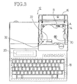
- Key input part 18 is disposed on an upper front side (the lower side in Fig.3) of the tape writer 12.
- the tape writer 12 is operated by an operator's key operation from the key input part 18.
- a power supply key for switching ON/OFF of the tape writer's power supply, character input key for inputting desired characters, symbols, etc., size key for setting the size of characters and symbols input by operations of character input keys, print key for printing by the print device installed in the tape writer 12, and various keys are installed on the key input part 18.
- a liquid crystal display 20 is disposed in the upper left side of the key input part 18. Characters, symbols or messages input by the key input part 18 are displayed on liquid crystal display 20.
- a tape cassette installation part 14 is disposed in the upper right portion of the key input part 18. Tape cassette 10 described below is installed in the tape cassette installation part 14. A tape cassette 10 is attached to and detached from the tape cassette installation part 14 through an opened cover 16, which opens and closes the tape cassette installation part 14 shown in Fig. 3.
- Thermal head 22 spool drive shaft 30, roller drive shaft 32, etc. are disposed in the tape cassette installation part 14.
- Thermal head 22 prints characters or symbols on film tape 34 by melting ink of a heat transfer ribbon 38 based on the print pattern of the characters or symbols.
- Thermal head 22 is installed in the front left side of the tape cassette installation part 14.
- Spool drive shaft 30 and roller drive shaft 32 transmit a rotational drive by pulse motor 24 to a ribbon winding spool 26 and an adjustment roller 28 disposed in the tape cassette 10.
- the spool drive shaft 30 is installed almost in the center of the tape cassette installation part 14, and the roller drive shaft 32 is installed in the left side of thermal head 22.
- the tape cassette installation part 14 is large enough to store all kinds of tape cassettes 10 having different widths corresponding to a tape width of various tapes (film tape 34, double-coated adhesive tape 36, and heat transfer ribbon 38) stored in tape cassette 10.
- a distinction sensor A or B for distinguishing a kind of tape cassette 10, a tape cutting device (not shown), etc. are installed in the tape cassette installation part 14.
- Tape writer 12 is controlled by CPU 40, and ROM 44, CGROM 46, RAM 48 and I/O device (I/O) 50 are connected to CPU 40 via a bus 42.
- ROM 44 memorizes the program by which CPU 40 controls tape writer 12. Based on the program, CPU 40 controls CGROM 46 and RAM 48, and also controls pulse motor 24, thermal head 22, liquid crystal display 20, etc. connected to CPU 40 via I/O device 50 according to the signal from key input part 18, sensor A and sensor B via I/O device 50.
- CGROM 46 memorizes print patterns of characters and symbols. CGROM 46 changes data of characters or symbols input by the control of CPU 40 into print patterns of the characters or the symbols.
- RAM 48 memorizes the print patterns, and RAM 48 memorizes print patterns of characters and symbols changed from data of the characters or the symbols by the control of CPU 40.
- I/O device 50 connects CPU 40, the input device of key input part 18, sensor A, sensor B, etc., and the output device of pulse motor 24, thermal head 22, liquid crystal display 20, etc.. I/O device 50 changes signals from the input device into a form that CPU 40 can read, and I/O device 50 changes signals from CPU 40 into a form enabling each output device to execute its operation.
- tape cassette 10 of the present invention attached to tape writer 12 of the above-mentioned structure is explained.
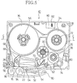
- Tape cassette 10 which stores supply spools and winding spools of tapes and ribbons (film tape 34, double-coated adhesive tape 36, and heat transfer ribbon 38) is installed detachably in the tape cassette installation part 14.
- Space 54 is formed in tape cassette 10 so that thermal head 22 can be provided in the space 54 when the tape cassette 10 is attached to the tape cassette installation part 14.
- Double-coated adhesive tape spool 56 is pivotably installed in the upper direction of the space 54.
- One side of double-coated adhesive tape 36 is covered with exfoliative sheet, and double-coated adhesive tape 36 is wound counterclockwise around the double-coated adhesive tape spool 56 with the exfoliative sheet facing outside.
- Adjustment roller 28 is pivotably installed in the left side of space 54.
- the adjustment roller 28 is engaged to roller drive shaft 32 on the tape writer 12 and the adjustment roller 28 is driven clockwise by roller drive shaft 32, when tape cassette 10 is attached to the tape cassette installation part 14.
- the double-coated adhesive tape 36 wound around the double-coated adhesive tape spool 56 is engaged to the adjustment roller 28 clockwise with its exfoliative sheet facing inside.
- the double-coated adhesive tape 36 is sent off to exit 58 by the clockwise rotation of the adjustment roller 28.
- Ribbon winding spool 26 is pivotably installed in the upper right direction of space 54.
- the ribbon winding spool 26 is engaged to spool drive shaft 30 on tape writer 12 and the ribbon winding spool 26 is driven to rotate counterclockwise by the spool drive shaft 30.
- Ribbon supplying spool 60 is pivotably installed in the lower right direction of ribbon winding spool 26.
- Heat transfer ribbon 38 having almost the same width as double-coated adhesive tape 36 is wound around the ribbon supplying spool 60 counterclockwise with its ink surface facing inside.
- the heat transfer ribbon 38 wound around the ribbon supplying spool 60 is led to thermal head 22 by guides 62 and 64 with its ink surface facing outside, and it is led to ribbon winding spool 26 by guides 66, 68, and 70 with its ink surface facing inside. Since the rotational drive of spool drive shaft 30 by pulse motor 24 rotates ribbon winding spool 26 counterclockwise, the heat transfer ribbon 38 led to ribbon winding spool 26 is wound by the rotation.
- Film tape spool 72 is pivotably installed in the upper right direction of the ribbon winding spool 26.
- Transparent film tape 34 of the same width as double-coated adhesive tape 36 is wound around the film tape spool 72 in a clockwise direction.
- the film tape 34 wound around the film tape spool 72 is led to the outside of the heat transfer ribbon 38 on the thermal head 22 by guides 74 and 64.
- the film tape 34 is led to the outside of the double-coated adhesive tape 36 on adjustment roller 28 by guide 76, and the film tape 34 is adjusted with the double-coated adhesive tape 36, and the film tape 34 is then sent off to the exit 58 with the double-coated adhesive tape 36.
- Support portion 92 is supported pivotably to tape cassette 10 around shaft 90 disposed on tape writer.
- Platen roller 94 is pivotably disposed on the support portion 92 confronting thermal head 22 via heat transfer ribbon 38 and film tape 34.
- Feeding roller 96 is pivotably disposed on the support portion 92 confronting adjustment roller 28 via double-coated adhesive tape 36 and film tape 34. Platen roller 94 is pressed against the support portion 92 when the support portion 92 is selectively biased by the bias member(not shown), and feeding roller 96 is pressed against adjustment roller 28.
- Second projection part 80 described below is installed in the upper left direction of film tape spool 72 of lower casing 78. Hole 82 is located in the right side of the second projection part 80. First projection part 84 is installed on upper casing 52 (not shown). The first projection part 84 projects its top through the hole 82 to the outside of tape cassette 10.
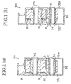
- tape cassette 10 of the above-mentioned structure is formed by combining either one of upper casing 52a or upper casing 52b whose guide ribs 86 have heights which differ by 6 mm and either one of lower casing 78a or lower casing 78b whose spools and outer walls 88 have heights which differ by 12 mm from one another corresponding to the tape width of the tape installed in tape cassette 10.
- the height of guide ribs 86 of upper casing 52a and upper casing 52b differ by 6mm from each other, and the height of guide rib 86 of upper casing 52a is 6mm lower than that of upper casing 52b.
- tape cassettes 10 formed by the upper casing 52a or 52b tape cassette 10a for storing tapes (film tape 34, double-coated adhesive tape 36, heat transfer ribbon 38) of 24mm width is formed by combining upper casing 52a and lower casing 78a.
- Tape cassette 10b for storing tapes (film tape 34, double-coated adhesive tape 36, heat transfer ribbon 38) of 18mm width is formed by combining upper casing 52b and lower casing 78a.
- lower casing 78a can form both tape cassette 10a for storing tapes (film tape 34, double-coated adhesive tape 36, heat transfer ribbon 38) of 24mm width and tape cassette 10b for storing tapes (film tape 34, double-coated adhesive tape 36, heat transfer ribbon 38) of 18mm width.
- the height of spools and outer walls 88 of lower casing 78a and the height of those of lower casing 78b differ by 12mm, and the height of spools and outer walls 88 of lower casing 78a are higher than the height of those of lower casing 78b. Therefore, among tape cassettes 10 formed by lower casing 78b whose spools and outer walls 88 are lower than those of lower casing 78a by 12mm and upper casing 52a or 52b, tape cassette 10c storing tapes of (film tape 34, double-coated adhesive tape 36, heat transfer ribbon 38) 12mm width is formed by combining upper casing 52a and lower casing 78b. Tape cassette 10d storing tapes (film tape 34, double-coated adhesive tape 36, heat transfer ribbon 38) of 6mm width is formed by combining upper casing 52b and lower casing 78b.
- lower casing 78b can form tape cassette 10c for storing tapes (film tape 34, double-coated adhesive tape 36, heat transfer ribbon 38) of 12mm width and tape cassette 10d for storing tapes (film tape 34, double-coated adhesive tape 36, heat transfer ribbon 38) of 6mm width.
- tape writer 12 to which tape cassette 10 is attached is provided hereafter.
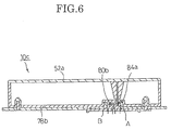
- Second projection part 80 of tape cassette 10 is formed corresponding to a kind of lower casing 78. That is, second projection part 80a of lower casing 78a does not project its top to the outside of tape cassette 10 (lower direction of tape cassette 10 shown in Fig.5). On the other hand, second projection part 80b of lower casing 78b projects its top to the outside of tape cassette 10 (lower direction of tape cassette 10 shown in Fig.5).
- first projection part 84 of tape cassette 10 is forced corresponding to a kind of upper casing 52. That is, first projection part 84a of upper casing 52a projects its top through hole 82 of lower casing 78 to the outside of tape cassette 10 (lower direction of tape cassette 10 shown in Fig.5), and first projection part 84b of upper casing 52b does not project its top to the outside of tape cassette 10 (lower direction of tape cassette 10 shown in Fig.5).
- Each of sensor A and sensor B which is the main element of the distinction means for distinguishing the kind of tape cassette 10 has a luminescence part and a receiving part of infrared radiation corresponding to first projection part 84 and the second projection part 80. Electric current is changed to infrared radiation and infrared radiation is generated in the luminescence part of sensor A (or sensor B). If infrared radiation is received in the receiving part, an electric charge is generated in the receiving part of sensor A (or sensor B).
- first projection part 84b (or second projection part 80a) is not inserted into the hollow of sensor A (or sensor B) when tape cassette 10 having first projection part 84b (or second projection part 80a) is attached to tape writer 12, the infrared radiation generated in the luminescence part is received in the receiving part.
- first projection part 84b (or second projection part 80b) is inserted into the hollow of sensor A (or sensor B) when tape cassette 10 having the first projection part 84b (or second projection part 80b) is attached to tape writer 12
- the infrared radiation generated in the luminescence part is cut off by first projection part 84a (or second projection part 80b), and the infrared radiation is not received in the receiving part.
- the generation of an electric charge is determined by whether infrared radiation is received in the receiving part or not, and the kind of upper casing 52 (or lower casing 78) is distinguished by the generation of the electric charge.
- the kind of cassette case 10 is distinguished by the combination of the distinguished upper casing 52 and lower casing 78.
- tape cassette 10 storing tapes (film tape 34, double-coated adhesive tape 36, heat transfer ribbon 38) of desired tape width is attached to tape cassette installation part 14, and the power supply of tape writer 12 is turned on by an operator.
- tape cassette 10c storing a tape of 12mm width is attached to tape writer 12.
- Tape cassette 10c is formed by upper casing 52a and lower casing 78b as shown in Fig.1. Both of the first projection part 84a and the second projection part 80b project their tops to the outside of the cassette casing 10c as shown in Fig. 6.
- CPU 40 of tape writer 12 reads the input characters or symbols via I/O device 50 and displays them on liquid crystal display 20.
- infrared radiation is generated in the luminescence parts of sensor A and sensor B by the signal from CPU 40 according to the program memorized in ROM 44.
- CPU 40 checks whether an electric charge is generated in the receiving part or not. Since first projection part 84a and second projection part 80b of tape cassette 10c are inserted into the hollows of sensor A and sensor B respectively, an electric charge is not generated in the receiving parts of sensor A and sensor B. As a result, CPU 40 identifies the kind of the installed tape cassette 10 as tape cassette 10c because CPU 40 reads that an electric charge is not generated in the radiation receiving parts of sensor A and sensor B.
- CPU 40 determines whether the size of the input characters or symbols fit in the tapes (film tape 34, double-coated adhesive tape 36, heat transfer ribbon 38) of 12mm width stored in tape cassette 10c. If the character size fits in the tape width, the characters or symbols are printed, and if the character size does not fit in the tape width, an error display appears on the display 20.
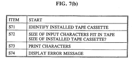
- Figs. 7(a) and 7(b) illustrate an operation sequence when character size set by the size key does not fit within the tape of the installed tape cassette case 10.
- CPU 40 identifies the installed tape cassette. The CPU 40 then determines in step S72 whether the size of input characters fits within the tape size of the installed cassette case 10. If the character size fits (step S72:YES), characters are printed on the tape in step S73. If, however, the character size does not fit (step S72:NO) an error message is displayed in step S74.
- CPU 40 controls the speed or the amount of rotational drive of adjustment roller 28 and ribbon winding spool 26 by controlling pulse motor 24.
- CPU 40 controls the speed and the feeding amount of double-coated adhesive tape 36 engaged to the adjustment roller 28, film tape 34 bonded to the double-coated adhesive tape 36, and heat transfer ribbon 38 wound around ribbon winding up spool 26.
- CPU 40 also controls the generation of heat from thermal head 22, and the print pattern stored in RAM 48 is printed from heat transfer ribbon 38 between thermal head 22 and platen roller 94 to film tape 34.
- the print surface of film tape 34 and the adhesive surface of the double-coated adhesive tape 36 are adjusted by adjustment roller 28 and feeding roller 96 pressed against the adjustment roller 28 sandwiching film tape 34 and double-coated adhesive tape 36.
- the tape 98 adjusted between the adjustment roller 28 and feeding roller 96 is fed to exit 58 and sent outside of tape writer 12 by rotational drive of the adjustment roller 28.
- tape 98 extended out of tape writer 12 is cut off from tape 98 inside tape writer 12 by the tape cutting device installed in tape writer 12, the process of making a tape 98 (a piece of tape) on which desired characters or symbols are printed is completed.
- tapes installed in each of tape cassettes 10a, 10b, 10c and 10d in this embodiment have tape widths of 24mm , 18mm, 12mm, and 6mm tape width, respectively, tapes of tape width other than 24mm, 18mm, 12mm, and 6mm are permitted to be used, and the difference between tape width is not restricted to 6mm.
- tape cassette 10 storing tapes (film tape 34, double-sided adhesive tape 36, heat transfer ribbon 38) of the same width can be formed by using more than two kinds of upper casings 52 or more than two kinds of lower casings 78, even if there are tapes of more than five kinds of tape width.
- the number of sensors is increased to identify tape cassette 10, and a plurality of projection parts (non-projection part) corresponding to each kind of upper casings 52 or lower casings 78 are formed in first projection part 84 of upper casing 52 or second projection part 80 of lower casing 78.
- an error message is displayed on the display 20 to inform the operator of the error and to change the character size or to exchange the tape cassette 10.
- the tape writer may be arranged to automatically change the character size to one which suits the installed tape cassette 10 and to begin printing.
- the tape cassette is shown as comprising three tapes, it may contain other numbers of tapes.
- the cassette may contain only a film tape and heat transfer ribbon.
Landscapes
- Impression-Transfer Materials And Handling Thereof (AREA)
- Handling Of Continuous Sheets Of Paper (AREA)
- Printers Characterized By Their Purpose (AREA)
Applications Claiming Priority (2)
| Application Number | Priority Date | Filing Date | Title |
|---|---|---|---|
| JP181188/91 | 1991-07-22 | ||
| JP3181188A JP2596263B2 (ja) | 1991-07-22 | 1991-07-22 | テープカセット製造方法及びテープカセット |
Publications (3)
| Publication Number | Publication Date |
|---|---|
| EP0526078A2 true EP0526078A2 (de) | 1993-02-03 |
| EP0526078A3 EP0526078A3 (en) | 1993-03-24 |
| EP0526078B1 EP0526078B1 (de) | 1995-02-22 |
Family
ID=16096404
Family Applications (1)
| Application Number | Title | Priority Date | Filing Date |
|---|---|---|---|
| EP92306670A Expired - Lifetime EP0526078B1 (de) | 1991-07-22 | 1992-07-21 | Bandkassetten und Zusammensetzungsverfahren dafür |
Country Status (4)
| Country | Link |
|---|---|
| US (1) | US5277503A (de) |
| EP (1) | EP0526078B1 (de) |
| JP (1) | JP2596263B2 (de) |
| DE (1) | DE69201467T2 (de) |
Cited By (11)
| Publication number | Priority date | Publication date | Assignee | Title |
|---|---|---|---|---|
| EP0574165A1 (de) * | 1992-06-05 | 1993-12-15 | Esselte Dymo N.V. | Druckgerät |
| EP0634274A3 (de) * | 1993-07-12 | 1995-07-26 | Esselte Dymo Nv | Druckvorrichtung. |
| US5492420A (en) * | 1992-10-06 | 1996-02-20 | Seiko Epson Corportion | Tape printing device and tape cartridge used therein |
| GB2270675B (en) * | 1992-09-11 | 1996-10-02 | Alps Electric Co Ltd | Label creation cassette |
| EP0734879A3 (de) * | 1995-03-29 | 1997-05-21 | Brother Ind Ltd | Drucker und zusammengesetzte Kassette für diesen Drucker, bestehend aus Druckband- und Farbbandkassette |
| US5857788A (en) * | 1995-11-10 | 1999-01-12 | Esselte Nv | Thermal printing device with direct thermal cassette |
| EP0919393A1 (de) * | 1997-11-27 | 1999-06-02 | Esselte N.V. | Nachfüllbare Farbbandkassette |
| US5934812A (en) * | 1992-10-06 | 1999-08-10 | Seiko Epson Corp. | Tape printing device and tape cartridge used therein |
| US6092946A (en) * | 1998-04-23 | 2000-07-25 | Esselte Nv | Tape printing apparatus and tape holding case with a sliding switch |
| EP1104701A3 (de) * | 1993-12-09 | 2001-12-19 | Brother Industries, Ltd | Tragbarer Drucker und Kassette dafür |
| EP1733895A1 (de) * | 1994-05-25 | 2006-12-20 | Brother Kogyo Kabushiki Kaisha | Bandkassette |
Families Citing this family (36)
| Publication number | Priority date | Publication date | Assignee | Title |
|---|---|---|---|---|
| JP2927146B2 (ja) * | 1993-06-15 | 1999-07-28 | ブラザー工業株式会社 | テープカセット |
| JP3370740B2 (ja) * | 1993-07-23 | 2003-01-27 | ブラザー工業株式会社 | テープユニット、テープカセット並びにテープ印字装置 |
| US6196740B1 (en) | 1994-05-25 | 2001-03-06 | Brother Kogyo Kabushiki Kaisha | Tape-shaped label printing device |
| US6042280A (en) * | 1995-05-25 | 2000-03-28 | Brother Kogyo Kabushiki Kaisha | Tape label printing device |
| JP3111445B2 (ja) * | 1995-03-29 | 2000-11-20 | ブラザー工業株式会社 | テープ状ラベル作成装置 |
| US6190069B1 (en) | 1994-05-25 | 2001-02-20 | Brother Kogyo Kabushiki Kaisha | Tape-shaped label printing device |
| US6132120A (en) * | 1995-03-29 | 2000-10-17 | Brother Kogyo Kabushiki Kaisha | Tape-shaped label printing device |
| US5793573A (en) * | 1995-06-07 | 1998-08-11 | International Business Machines Corporation | Hybrid actuator servo actuated tape drive having a pivotally mounted motion transmission member |
| US5677806A (en) * | 1995-06-07 | 1997-10-14 | International Business Machines Corporation | Head locking apparatus in a servo system so that the head can read and write data on a tape without servo trucks |
| US5710681A (en) * | 1995-06-07 | 1998-01-20 | International Business Machines Corporation | Pivot bearing having no moving parts for use in a high density data tape drive |
| US6955318B2 (en) * | 2000-10-19 | 2005-10-18 | Brother Kogyo Kabushiki Kaisha | Tape cassette and tape unit |
| US6644701B2 (en) | 2002-01-14 | 2003-11-11 | Shape Corporation | Bumper energy absorber with foam and non-foam pieces |
| US7445324B2 (en) * | 2005-09-29 | 2008-11-04 | Brother Kogyo Kabushiki Kaisha | Ink cartridges |
| US7222951B2 (en) * | 2005-09-29 | 2007-05-29 | Brother Kogyo Kabushiki Kaisha | Ink cartridges |
| BRPI0923680B1 (pt) | 2008-12-25 | 2020-01-28 | Brother Kogyo Kabushiki Kaisha | fita cassete |
| PT2370265E (pt) | 2008-12-25 | 2013-10-04 | Brother Ind Ltd | Cassete de fita e impressora de fita |
| JP5136503B2 (ja) | 2009-03-31 | 2013-02-06 | ブラザー工業株式会社 | テープカセット |
| US12296580B2 (en) | 2009-03-31 | 2025-05-13 | Brother Kogyo Kabushiki Kaisha | Tape cassette |
| JP4947085B2 (ja) * | 2009-03-31 | 2012-06-06 | ブラザー工業株式会社 | テープカセット |
| CN104691118B (zh) | 2009-03-31 | 2017-10-13 | 兄弟工业株式会社 | 带盒 |
| JP4962521B2 (ja) * | 2009-03-31 | 2012-06-27 | ブラザー工業株式会社 | テープカセットおよびテープ印字装置 |
| EP2415612B1 (de) | 2009-03-31 | 2019-09-25 | Brother Kogyo Kabushiki Kaisha | Bandkassette |
| WO2010113445A1 (en) | 2009-03-31 | 2010-10-07 | Brother Kogyo Kabushiki Kaisha | Tape cassette and tape printer |
| EP4067095B1 (de) | 2009-03-31 | 2025-08-20 | Brother Kogyo Kabushiki Kaisha | Bandkassette |
| DK2414165T3 (da) * | 2009-03-31 | 2014-05-05 | Brother Ind Ltd | Båndkassette og båndprinter |
| EP2261040B1 (de) | 2009-06-10 | 2012-02-08 | Brother Kogyo Kabushiki Kaisha | Drucker |
| US8641304B2 (en) | 2009-06-30 | 2014-02-04 | Brother Kogyo Kabushiki Kaisha | Tape cassette |
| US20100329767A1 (en) * | 2009-06-30 | 2010-12-30 | Brother Kogyo Kabushiki Kaisha | Tape cassette |
| JP5326950B2 (ja) * | 2009-09-09 | 2013-10-30 | ブラザー工業株式会社 | テープカセット |
| EP2514600B1 (de) | 2009-12-16 | 2015-01-21 | Brother Kogyo Kabushiki Kaisha | Bandkassette |
| WO2011080840A1 (ja) | 2009-12-28 | 2011-07-07 | ブラザー工業株式会社 | テープカセット |
| JP5093265B2 (ja) | 2010-02-26 | 2012-12-12 | ブラザー工業株式会社 | テープカセット |
| US8384750B2 (en) | 2010-03-31 | 2013-02-26 | Brother Kogyo Kabushiki Kaisha | Printing apparatus |
| EP2371558B1 (de) | 2010-03-31 | 2015-04-15 | Brother Kogyo Kabushiki Kaisha | Wärmedrucker |
| JP6019309B2 (ja) * | 2012-11-27 | 2016-11-02 | フジコピアン株式会社 | インクリボンカセット |
| JP6561750B2 (ja) * | 2015-09-15 | 2019-08-21 | セイコーエプソン株式会社 | テープカートリッジ |
Family Cites Families (15)
| Publication number | Priority date | Publication date | Assignee | Title |
|---|---|---|---|---|
| DE3005260A1 (de) * | 1980-02-13 | 1981-08-20 | Klaus 5600 Wuppertal Turbon | Aus einem deckel- und einem bodenteil bestehende farbbandkassette |
| JPS6050153B2 (ja) * | 1980-10-28 | 1985-11-07 | 株式会社リコー | 印字装置 |
| JPS6310305Y2 (de) * | 1980-12-11 | 1988-03-28 | ||
| JPS5978879A (ja) * | 1982-10-28 | 1984-05-07 | Brother Ind Ltd | プリンタのリボンカセツト判別装置 |
| JPS59222380A (ja) * | 1983-06-02 | 1984-12-14 | Fujitsu Ltd | シリアルプリンタのリボン識別機構 |
| JPS6015188A (ja) * | 1983-07-07 | 1985-01-25 | Tokyo Electric Co Ltd | サ−マルプリンタのリボンカセツト |
| US4531690A (en) * | 1984-03-12 | 1985-07-30 | Condy Robert J | Variable capacity reusable dual tape dispensing cartridge |
| DE3421407C1 (de) * | 1984-06-08 | 1985-12-19 | Triumph-Adler Aktiengesellschaft für Büro- und Informationstechnik, 8500 Nürnberg | Farbbandkassette fuer Schreib- oder aehnliche Maschinen |
| JPH0630449Y2 (ja) * | 1986-09-08 | 1994-08-17 | ブラザー工業株式会社 | 印字装置 |
| US4966476A (en) * | 1987-12-29 | 1990-10-30 | Brother Kogyo Kabushiki Kaisha | Tape printer |
| JPH01195088A (ja) * | 1988-01-30 | 1989-08-04 | Nec Home Electron Ltd | 熱写転プリンタ |
| JPH0434048Y2 (de) * | 1988-10-17 | 1992-08-13 | ||
| JPH02241780A (ja) * | 1989-03-16 | 1990-09-26 | Fujitsu Ltd | プリンタの据置型インクリボンカセット |
| US5022771A (en) * | 1989-07-17 | 1991-06-11 | Kroy Inc. | Thermal printing apparatus and tape supply cartridge therefor |
| US5073052A (en) * | 1991-02-23 | 1991-12-17 | Ncr Corporation | Reuseable ink ribbon cassette adjustable to different ribbon widths and method of use |
-
1991
- 1991-07-22 JP JP3181188A patent/JP2596263B2/ja not_active Expired - Fee Related
-
1992
- 1992-06-29 US US07/905,517 patent/US5277503A/en not_active Expired - Lifetime
- 1992-07-21 EP EP92306670A patent/EP0526078B1/de not_active Expired - Lifetime
- 1992-07-21 DE DE69201467T patent/DE69201467T2/de not_active Expired - Lifetime
Cited By (28)
| Publication number | Priority date | Publication date | Assignee | Title |
|---|---|---|---|---|
| US5605404A (en) * | 1992-02-12 | 1997-02-25 | Seiko Epson Corporation | Tape printing device and tape cartridge used therein |
| US5601375A (en) * | 1992-05-06 | 1997-02-11 | Esselte N.V. | Automatic tape detecting and tape width identifying printing apparatus and tape holder |
| EP0574165A1 (de) * | 1992-06-05 | 1993-12-15 | Esselte Dymo N.V. | Druckgerät |
| US5456545A (en) * | 1992-06-05 | 1995-10-10 | Esselte Dymo N.V. | Tape printing apparatus and tape holding case |
| GB2270675B (en) * | 1992-09-11 | 1996-10-02 | Alps Electric Co Ltd | Label creation cassette |
| US5752777A (en) * | 1992-10-06 | 1998-05-19 | Seiko Epson Corporation | Tape printing device and tape cartridge used therein |
| US5934812A (en) * | 1992-10-06 | 1999-08-10 | Seiko Epson Corp. | Tape printing device and tape cartridge used therein |
| US5599119A (en) * | 1992-10-06 | 1997-02-04 | Seiko Epson Corporation | Tape printing device and tape cartridge used therein |
| EP0592198A3 (en) * | 1992-10-06 | 1996-04-03 | Seiko Epson Corp | Tape printing device and tape cartridge used therein |
| US5492420A (en) * | 1992-10-06 | 1996-02-20 | Seiko Epson Corportion | Tape printing device and tape cartridge used therein |
| EP1132216A3 (de) * | 1992-10-06 | 2002-01-02 | Seiko Epson Corporation | Banddruckvorrichtung und Bandkassette zur Verwendung hierbei |
| US5997194A (en) * | 1992-10-06 | 1999-12-07 | Seiko Epson Corporation | Tape printing device and tape cartridge used therein |
| EP1134086A3 (de) * | 1992-10-06 | 2002-01-02 | Seiko Epson Corporation | Banddruckvorrichtung und Bandkassette zur Verwendung hierbei |
| US5765954A (en) * | 1992-10-06 | 1998-06-16 | Seiko Epson Corporation | Tape printing device and tape cartridge used therein |
| US5967678A (en) * | 1992-10-06 | 1999-10-19 | Seiko Epson Corp. | Tape printing device and tape cartridge used therein |
| US5887993A (en) * | 1992-10-06 | 1999-03-30 | Seiko Epson Corporation | Tape printing device and tape cartridge used therein |
| US5961225A (en) * | 1992-10-06 | 1999-10-05 | Seiko Epson Corporation | Tape printing device and tape cartridge used therein |
| EP0634274A3 (de) * | 1993-07-12 | 1995-07-26 | Esselte Dymo Nv | Druckvorrichtung. |
| US5540510A (en) * | 1993-07-12 | 1996-07-30 | Esselte Dymo N.V. | Printing device for receiving at least two different types of tape holding cases |
| EP1561588A3 (de) * | 1993-12-09 | 2005-08-24 | Brother Industries, Ltd | Bandzufuhrkassette |
| EP1104701A3 (de) * | 1993-12-09 | 2001-12-19 | Brother Industries, Ltd | Tragbarer Drucker und Kassette dafür |
| EP1733895A1 (de) * | 1994-05-25 | 2006-12-20 | Brother Kogyo Kabushiki Kaisha | Bandkassette |
| US5727888A (en) * | 1995-03-29 | 1998-03-17 | Brother Kogyo Kabushiki Kaisha | Printer and a composite cassette including a tape cassette and a ribbon cassette used in the printer |
| EP0734879A3 (de) * | 1995-03-29 | 1997-05-21 | Brother Ind Ltd | Drucker und zusammengesetzte Kassette für diesen Drucker, bestehend aus Druckband- und Farbbandkassette |
| US5857788A (en) * | 1995-11-10 | 1999-01-12 | Esselte Nv | Thermal printing device with direct thermal cassette |
| US7097372B1 (en) | 1997-11-27 | 2006-08-29 | Esselte N.V. | Refillable tape cassette |
| EP0919393A1 (de) * | 1997-11-27 | 1999-06-02 | Esselte N.V. | Nachfüllbare Farbbandkassette |
| US6092946A (en) * | 1998-04-23 | 2000-07-25 | Esselte Nv | Tape printing apparatus and tape holding case with a sliding switch |
Also Published As
| Publication number | Publication date |
|---|---|
| DE69201467D1 (de) | 1995-03-30 |
| US5277503A (en) | 1994-01-11 |
| JPH0524291A (ja) | 1993-02-02 |
| JP2596263B2 (ja) | 1997-04-02 |
| DE69201467T2 (de) | 1995-07-13 |
| EP0526078B1 (de) | 1995-02-22 |
| EP0526078A3 (en) | 1993-03-24 |
Similar Documents
| Publication | Publication Date | Title |
|---|---|---|
| EP0526078B1 (de) | Bandkassetten und Zusammensetzungsverfahren dafür | |
| US5997194A (en) | Tape printing device and tape cartridge used therein | |
| US7121751B2 (en) | Placing printing elements and mark sensor at proper positions with respect to the cutter member | |
| US6132120A (en) | Tape-shaped label printing device | |
| EP0661656B1 (de) | Streifendrucker | |
| EP0862517B1 (de) | Streifendrucker | |
| US5934812A (en) | Tape printing device and tape cartridge used therein | |
| US7258502B2 (en) | Tape producing apparatus | |
| EP0769385A1 (de) | Etikettenbanddrucker benutzbar mit Farbbandkassetten mit neu zugefügten Farben | |
| EP0769386B1 (de) | Etikettenbanddrucker | |
| JP3420544B2 (ja) | テープカートリッジ | |
| JP2893499B2 (ja) | テープカートリッジおよびテープライタ | |
| JP3539007B2 (ja) | テープ状ラベル作成装置 | |
| JP3511985B2 (ja) | テープユニット | |
| JP3002817B2 (ja) | テープ印字装置 | |
| EP0747228A1 (de) | Etikettendrucker und Verfahren zum Bedrucken von identischen mehrfarbigen Etiketten | |
| JP3091175B2 (ja) | テープ印字装置 | |
| JPH06293146A (ja) | テープ印字装置 | |
| JPH09109472A (ja) | テープ状ラベル作成装置 | |
| JPH07132657A (ja) | テープ印刷装置 | |
| JP2007083491A (ja) | 印刷装置 | |
| HK1015738B (en) | Tape printers |
Legal Events
| Date | Code | Title | Description |
|---|---|---|---|
| PUAI | Public reference made under article 153(3) epc to a published international application that has entered the european phase |
Free format text: ORIGINAL CODE: 0009012 |
|
| PUAL | Search report despatched |
Free format text: ORIGINAL CODE: 0009013 |
|
| AK | Designated contracting states |
Kind code of ref document: A2 Designated state(s): BE DE FR GB |
|
| AK | Designated contracting states |
Kind code of ref document: A3 Designated state(s): BE DE FR GB |
|
| 17P | Request for examination filed |
Effective date: 19930624 |
|
| 17Q | First examination report despatched |
Effective date: 19930804 |
|
| GRAA | (expected) grant |
Free format text: ORIGINAL CODE: 0009210 |
|
| AK | Designated contracting states |
Kind code of ref document: B1 Designated state(s): BE DE FR GB |
|
| ET | Fr: translation filed | ||
| REF | Corresponds to: |
Ref document number: 69201467 Country of ref document: DE Date of ref document: 19950330 |
|
| PLBE | No opposition filed within time limit |
Free format text: ORIGINAL CODE: 0009261 |
|
| STAA | Information on the status of an ep patent application or granted ep patent |
Free format text: STATUS: NO OPPOSITION FILED WITHIN TIME LIMIT |
|
| 26N | No opposition filed | ||
| REG | Reference to a national code |
Ref country code: GB Ref legal event code: IF02 |
|
| PGFP | Annual fee paid to national office [announced via postgrant information from national office to epo] |
Ref country code: GB Payment date: 20110622 Year of fee payment: 20 |
|
| PGFP | Annual fee paid to national office [announced via postgrant information from national office to epo] |
Ref country code: FR Payment date: 20110727 Year of fee payment: 20 |
|
| PGFP | Annual fee paid to national office [announced via postgrant information from national office to epo] |
Ref country code: DE Payment date: 20110729 Year of fee payment: 20 |
|
| PGFP | Annual fee paid to national office [announced via postgrant information from national office to epo] |
Ref country code: BE Payment date: 20110727 Year of fee payment: 20 |
|
| REG | Reference to a national code |
Ref country code: DE Ref legal event code: R071 Ref document number: 69201467 Country of ref document: DE |
|
| REG | Reference to a national code |
Ref country code: DE Ref legal event code: R071 Ref document number: 69201467 Country of ref document: DE |
|
| BE20 | Be: patent expired |
Owner name: *BROTHER KOGYO K.K. Effective date: 20120721 |
|
| REG | Reference to a national code |
Ref country code: GB Ref legal event code: PE20 Expiry date: 20120720 |
|
| PG25 | Lapsed in a contracting state [announced via postgrant information from national office to epo] |
Ref country code: DE Free format text: LAPSE BECAUSE OF EXPIRATION OF PROTECTION Effective date: 20120724 Ref country code: GB Free format text: LAPSE BECAUSE OF EXPIRATION OF PROTECTION Effective date: 20120720 |