EP0526108A2 - Boîtier pour des dispositifs de connection de fibres optiques - Google Patents
Boîtier pour des dispositifs de connection de fibres optiques Download PDFInfo
- Publication number
- EP0526108A2 EP0526108A2 EP92306747A EP92306747A EP0526108A2 EP 0526108 A2 EP0526108 A2 EP 0526108A2 EP 92306747 A EP92306747 A EP 92306747A EP 92306747 A EP92306747 A EP 92306747A EP 0526108 A2 EP0526108 A2 EP 0526108A2
- Authority
- EP
- European Patent Office
- Prior art keywords
- closure
- cable
- optical fiber
- end portion
- longitudinally extending
- Prior art date
- Legal status (The legal status is an assumption and is not a legal conclusion. Google has not performed a legal analysis and makes no representation as to the accuracy of the status listed.)
- Granted
Links
Images

Classifications
-
- G—PHYSICS
- G02—OPTICS
- G02B—OPTICAL ELEMENTS, SYSTEMS OR APPARATUS
- G02B6/00—Light guides; Structural details of arrangements comprising light guides and other optical elements, e.g. couplings
- G02B6/24—Coupling light guides
- G02B6/255—Splicing of light guides, e.g. by fusion or bonding
- G02B6/2558—Reinforcement of splice joint
-
- G—PHYSICS
- G02—OPTICS
- G02B—OPTICAL ELEMENTS, SYSTEMS OR APPARATUS
- G02B6/00—Light guides; Structural details of arrangements comprising light guides and other optical elements, e.g. couplings
- G02B6/24—Coupling light guides
- G02B6/36—Mechanical coupling means
- G02B6/38—Mechanical coupling means having fibre to fibre mating means
- G02B6/3807—Dismountable connectors, i.e. comprising plugs
- G02B6/381—Dismountable connectors, i.e. comprising plugs of the ferrule type, e.g. fibre ends embedded in ferrules, connecting a pair of fibres
- G02B6/3816—Dismountable connectors, i.e. comprising plugs of the ferrule type, e.g. fibre ends embedded in ferrules, connecting a pair of fibres for use under water, high pressure connectors
-
- G—PHYSICS
- G02—OPTICS
- G02B—OPTICAL ELEMENTS, SYSTEMS OR APPARATUS
- G02B6/00—Light guides; Structural details of arrangements comprising light guides and other optical elements, e.g. couplings
- G02B6/24—Coupling light guides
- G02B6/36—Mechanical coupling means
- G02B6/38—Mechanical coupling means having fibre to fibre mating means
- G02B6/3807—Dismountable connectors, i.e. comprising plugs
- G02B6/3887—Anchoring optical cables to connector housings, e.g. strain relief features
- G02B6/3888—Protection from over-extension or over-compression
-
- G—PHYSICS
- G02—OPTICS
- G02B—OPTICAL ELEMENTS, SYSTEMS OR APPARATUS
- G02B6/00—Light guides; Structural details of arrangements comprising light guides and other optical elements, e.g. couplings
- G02B6/44—Mechanical structures for providing tensile strength and external protection for fibres, e.g. optical transmission cables
- G02B6/4401—Optical cables
- G02B6/4429—Means specially adapted for strengthening or protecting the cables
- G02B6/44384—Means specially adapted for strengthening or protecting the cables the means comprising water blocking or hydrophobic materials
-
- G—PHYSICS
- G02—OPTICS
- G02B—OPTICAL ELEMENTS, SYSTEMS OR APPARATUS
- G02B6/00—Light guides; Structural details of arrangements comprising light guides and other optical elements, e.g. couplings
- G02B6/44—Mechanical structures for providing tensile strength and external protection for fibres, e.g. optical transmission cables
- G02B6/4439—Auxiliary devices
- G02B6/444—Systems or boxes with surplus lengths
- G02B6/44528—Patch-cords; Connector arrangements in the system or in the box
-
- G—PHYSICS
- G02—OPTICS
- G02B—OPTICAL ELEMENTS, SYSTEMS OR APPARATUS
- G02B6/00—Light guides; Structural details of arrangements comprising light guides and other optical elements, e.g. couplings
- G02B6/24—Coupling light guides
- G02B6/255—Splicing of light guides, e.g. by fusion or bonding
-
- G—PHYSICS
- G02—OPTICS
- G02B—OPTICAL ELEMENTS, SYSTEMS OR APPARATUS
- G02B6/00—Light guides; Structural details of arrangements comprising light guides and other optical elements, e.g. couplings
- G02B6/46—Processes or apparatus adapted for installing or repairing optical fibres or optical cables
- G02B6/56—Processes for repairing optical cables
- G02B6/564—Repair sets
Definitions
- This invention relates to a closure for optical fiber connective arrangements.
- Drop cables are those cables which extend from distribution cables at the street to the premises.
- the sought after closure is relatively small in size yet able to accommodate a suitable number of splices for fiber-in-the-loop.
- fiber closures are available in the prior art.
- a tubular cover having a closed end and an open end is adapted to receive and be sealed to a cable termination assembly.
- the cable termination assembly includes cable entry facilities through which the cables to be spliced are routed.
- a support member extends from the cable entry facilities and has a free end disposed adjacent to the closed end of the cover.
- the support member includes a support base for supporting an optical fiber breakout and a plurality of optical fiber splice trays.
- each tray Mounted centrally of each tray is at least one organizing module each of which is capable of holding a plurality of optical fiber connective arrangements.
- Each tray is capable of holding a plurality of organizing modules which may be added as needed.
- the prior art also includes at least one drop repair closure. See U.S. patent 4,820,007.
- a splice tray includes provisions on one side for holding optical fiber splices and metallic conductor splices on an opposite side.
- An electrical bonding and gripping assembly is adapted to be mounted on the splice tray.
- the closure also includes mating cover portions which are moved into engagement with each other to enclose the tray. Also, a waterblocking encapsulant may be introduced into the closure.
- the last described prior art drop repair closure is designed primarily for mechanical and fusion splices which require long lengths of fiber slack for splicing and bend radius controllers. Because of the amount of slack, a fiber organizer and splice holder are required for storage of slack fiber. Also, it has a relatively large size compared to the transverse cross section of cables which are spliced therein. As such, it is more vulnerable than desired to repeated engagement by excavation tools. Further, because of its relatively large size compared to the cables to be spliced therein, the amount of encapsulant necessary to fill it is relatively large. Gripping of the cables at the ends of the closure is accomplished with the same assembly which is used for bonding. Lastly, the only effective barrier to moisture ingress is the encapsulant.
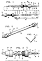
- FIGS. 1 and 2 there is shown an optical fiber closure of this invention which is designated generally by the numeral 20.
- the closure 20 is adapted to provide an enclosure in which optical fibers 22-22 of an optical fiber cable 24 are spliced to optical fibers of another optical fiber cable 26.
- the optical fibers 22-22 comprise a core which is disposed in a core tube 28.
- a metallic shield 29 which is corrugated and which has an overlapped seam 31.
- a plastic jacket 33 is disposed about the metallic shield 29.
- the cable sheath gripping and sealing assembly 40 includes a collar 42 having a truncated conically shaped portion 44 and a cylindrically shaped portion 46 which is threaded internally.
- Acollet grip portion 48 is adapted to have the cable end portion extend therethrough as is a grommet 51.
- the grommet 51 is made of a neoprene or other suitable elastomeric material and has a truncated conical shape such that a small diameter portion thereof is adapted to be received in an externally threaded end portion 53 of an adapter 55.
- the externally threaded end of the adapter 55 is adapted to be received in the internally threaded end of the collar 42.
- a housing 60 Connected to the cable sheath gripping and sealing assembly 40 is a housing 60 (see FIGS. 1 and 2) in the form of a tubular member.
- the housing 60 is an elongated tubular member having outer and inner diameters of about 2.5 and 2.2 cm, respectively, and being made of a suitable plastic material.
- An end portion of the housing 60 is adapted to become secured within an enlarged unthreaded portion 62 (see FIG. 3) of the adapter 55, thereby providing a watertight seal.
- An adhesive material may be used to secure the end portion of the housing 60 within an adapter 55, thereby providing a watertight seal.
- the bonding and support member 70 Disposed within the housing 60 is a longitudinally extending electrical bonding and support member 70 (see FIGS. 1 and 4).
- the bonding and support member 70 which extends generally collinearly with the housing 60 has a dual function. First, it is adapted to support optical fibers 22-22 of the cables which extend into the closure and to support connections therebetween. Secondly, the member 70 functions as an electrical bonding member to carry electrical continuity across the connections from a metallic shield portion of one cable to a metallic shield portion of the other cable.
- the bonding and support member 70 is made of metal, has a V-shaped cross section (see FIG 4) transverse to a longitudinal axis of the closure and has a length of about 37 cm. Also, as can be seen in FIGS. 1 and 4, inner surfaces of the end portions of the member 70 are provided with upstanding portions 71-71 to enhance gripping of jacketed cable portions which extend into member 70.
- the closure 20 is completed with a second cable gripping and sealing assembly 40 which is caused to grip the end portion of the cable 26 and which has its adapter 55 secured to an opposite end of the housing 60.
- each prepared end portion of a cable to be spliced has about 15.2 cm of exposed fibers, about 0.6 cm of exposed core tube and about 1.9 cm of exposed metallic shield.
- the craftsperson moves unassembled portions of a cable gripping and sealing assembly 40 over the end portion of a first cable, which in this instance is the cable 26, for a distance which is sufficient then to move slidably a housing 60 onto the first one of the cables to be spliced.
- the unassembled portions of a cable gripping and sealing assembly 40 are moved over the end portion of a second cable, which in this instance is the cable 24, that is to be spliced to the first. This is accomplished in a manner such that the elements of each assembly are oriented with respect to its associated cable end portion as shown in FIGS. 1 and 3.
- the craftsperson positions the first or left hand cable 26 as viewed in FIG. 5 such that about 2.5 cm of the jacketed portion extends into a left hand end of the bonding and support member 70.
- Three turns of a vinyl adhesive tape 72 are wrapped about the jacketed portion of the end portion of the cable 26 and the bonding and support member 70 (see FIG. 5).
- a tie 75 is wrapped about the tape to secure the tape to the jacketed portion of the cable 26 and to the left end portion of the bonding and support member 70.
- the craftsperson positions the other or second cable 24, the right hand cable end portion as viewed in FIG. 5, such that about 6.4 cm of the jacketed end portion is positioned in the bonding and supporting member 70.
- three turns of an adhesive vinyl tape 77 are used to secure this cable end portion to the supporting an bonding member; however unlike for the cable 26, the securement of the cable 24 is only temporary.
- the craftsperson positions the bonding and support member 70 with respect to apparatus (not shown) which is used to connect fibers of the cable 26 to fibers of the cable 24 with connective arrangements 76-76.
- apparatus not shown
- Such splices may be made by using AT&T's CSL Lightsplice S fiber optic splice. The slack in the fibers allows portions of them to be moved outside the member 70 so that the splicing operation may be performed.
- the three turns of adhesive tape 77 are removed from the right hand cable end portion and the right hand cable 24 is moved to the right as viewed in FIG. 5 while the fibers and splices are repositioned in the support member. Care is taken so that the fibers are not taut. Then, turns of an adhesive tape 78 (see FIG. 6) are wrapped about the jacketed portion of cable 24 and the right hand end (as viewed in FIG. 6) of the support member 70 and a tie wrap 79 applied to secure the jacketed portion to the support member.
- the craftsperson separates an overlapped portion 20 of the corrugated shield portion of the cable 26 which is exposed within the support member 70 and positions that overlapped portion in engagement with the bonding and support member 70 (see FIGS. 6 and 7).
- An electrical bonding clip 80 (see FIGS. 4 and 5) is caused to be disposed on the portion of the metallic shield and over an edge portion of the bonding and support member 70 to hold the portion of the shield in electrical engagement with the bonding and support member. This step is repeated for the end portion of the cable 24 at an opposite end of the member 70.
- the housing 60 is moved slidably along the cable 26 over the bonding and support member 70 and an adhesive material applied about an outer surface of each end portion thereof.
- the threaded adapters 55-55 are moved slidably to cause each end of the housing 60 to be received in the enlarged unthreaded end 62 of an adapter.
- the grommet, collet grip and collar of each cable gripping and sealing the assembly are moved to cause the grommet and grip to be received in the adapter.
- the collar 42 is turned threadably onto the associated adapter to cause the grommet and grip to become disposed in compressive engagement with the cable extending therethrough to seal the cable against the ingress of moisture.
- the housing 60 also is provided with several access ports 90-90.
- the craftsperson may remove a plug 92 from each port 90 and position a feed end of a funnel 94 (see FIG. 8) in the port.
- a suitable encapsulant material such as AT&T D1000 encapsulant, for example, then is introduced into the closure 20 to provide additional waterblocking capability.
- the closure 20 of this invention is one in which there is very little slack in the optical fibers. No bend radius controllers are necessary. There is no substantial intended curvature in any of the associated connected pairs of optical fibers. Indeed the length of each associated connected pair of fibers within the electrical bonding and support member is substantially equal to the length of the electrical bonding and support member. Because the fibers are not taut, there may be some undulations in their paths. What is important is that unlike in prior art closures where fiber organizers, for example, are used and where bend diameters may be as low as in the 7.6 to 10.2 cm range, the only curvature of the fibers in the closure of this invention is that of relatively large radii of curvature indulations.
- the closure 20 of this invention is referred to as an in-line closure.
- a cable enters the closure at each end and is substantially aligned with the longitudinal centerline of the closure.
- the closure itself has a relatively small profile compared to the cables which are connected therein.
- the diameter of the housing 60 is relatively close to the diameter of each of the cables to be connected together.
- the housing 60 has an outer diameter of 2.5 cm, as mentioned hereinbefore, whereas each of the cables has a diameter of about 1 cm. As such its vulnerability to excavation problems is diminished and the requirements for encapsulant are reduced substantially.
- the closure of the preferred embodiment is suitably sized for use in the local loop in that it can accommodate four connected fiber pairs.
- the connector which is preferred. It does not require that fiber ends be polished prior to assembly, and it is relatively simple to use to provide a connective arrangement. Accordingly, the apparatus needed to perform the connectorization is relatively uncomplicated and requires only a relatively small length of fiber of each cable be moved outside the electrical bonding and support member 70. When those portions of the lengths which are moved outside the bonding and support member to allow the connecting process to be carried out are repositioned in the support member and moved by removing the temporary securement at the right hand end, as viewed in FIG. 5, not much additional length of support member is required to eliminate the slack. As a result, the length of the closure is not large.
- the bonding and support member 70 also functions as a gauging member.
- the fibers of the cable which have been prepared with predetermined exposed lengths of the fibers, core tubes shields and jackets are disposed so that the fibers overlap to allow splicing.
- the fibers are not taut but are substantially without slack.
- the bonding and support member 70 floats mechanically within the closure. It is not used to transfer forces from one cable to the other as in some prior art closures. Rather the transfer of forces is effected through the connection between the cable gripping and sealing assemblies 40-40 and the housing 60.
- a dual water barrier is provided. Not only is an encapsulant used, but also the cable gripping and sealing assembly at each end of the housing 60 provides excellent sealing against the cable.
Landscapes
- Physics & Mathematics (AREA)
- General Physics & Mathematics (AREA)
- Optics & Photonics (AREA)
- Engineering & Computer Science (AREA)
- Plasma & Fusion (AREA)
- Cable Accessories (AREA)
- Mechanical Coupling Of Light Guides (AREA)
- Light Guides In General And Applications Therefor (AREA)
Applications Claiming Priority (2)
| Application Number | Priority Date | Filing Date | Title |
|---|---|---|---|
| US07/736,850 US5185844A (en) | 1991-07-29 | 1991-07-29 | Closure for optical fiber connective arrangements and method of providing same |
| US736850 | 1991-07-29 |
Publications (3)
| Publication Number | Publication Date |
|---|---|
| EP0526108A2 true EP0526108A2 (fr) | 1993-02-03 |
| EP0526108A3 EP0526108A3 (en) | 1993-06-30 |
| EP0526108B1 EP0526108B1 (fr) | 1998-09-23 |
Family
ID=24961564
Family Applications (1)
| Application Number | Title | Priority Date | Filing Date |
|---|---|---|---|
| EP92306747A Expired - Lifetime EP0526108B1 (fr) | 1991-07-29 | 1992-07-23 | Boítier pour des dispositifs de connection de fibres optiques |
Country Status (7)
| Country | Link |
|---|---|
| US (1) | US5185844A (fr) |
| EP (1) | EP0526108B1 (fr) |
| CN (1) | CN1036872C (fr) |
| CA (1) | CA2073481C (fr) |
| DE (1) | DE69227079T2 (fr) |
| MX (1) | MX9204401A (fr) |
| TW (1) | TW213988B (fr) |
Cited By (3)
| Publication number | Priority date | Publication date | Assignee | Title |
|---|---|---|---|---|
| WO2002063359A3 (fr) * | 2001-02-02 | 2003-09-18 | Tycom Us Inc | Connexion de cable etanche |
| DE10009845B4 (de) * | 2000-03-01 | 2011-06-01 | Escha Bauelemente Gmbh | Steckverbinder für einen Lichtwellenleiter |
| WO2015175363A1 (fr) * | 2014-05-12 | 2015-11-19 | Corning Optical Communications LLC | Ensembles câble à fibres optiques pour la terminaison d'un câble à fibres optiques et ses procédés de fabrication |
Families Citing this family (58)
| Publication number | Priority date | Publication date | Assignee | Title |
|---|---|---|---|---|
| US5440665A (en) * | 1993-04-16 | 1995-08-08 | Raychem Corporation | Fiber optic cable system including main and drop cables and associated fabrication method |
| FR2729230B1 (fr) * | 1995-01-09 | 1997-03-28 | Crespel Daniel | Dispositif de fixation, de reprise de masse et d'etancheite pour cable optique |
| US5802715A (en) * | 1995-01-17 | 1998-09-08 | Thomas & Betts Corporation | Method of sealing an elongate cable splice |
| US5613298A (en) * | 1995-01-17 | 1997-03-25 | Thomas & Betts Corporation | Forced encapsulation cable splice enclosure |
| US5647045A (en) * | 1996-02-23 | 1997-07-08 | Leviton Manufacturing Co., Inc. | Multi-media connection housing |
| US5943462A (en) * | 1997-11-12 | 1999-08-24 | Methode Electronics, Inc. | Fiber optic stub assembly having a water resistant barrier and method for manufacturing the same |
| US6382845B1 (en) * | 1999-03-02 | 2002-05-07 | Ameritech Corporation | Fiber optic patch kit and method for using same |
| US6522804B1 (en) * | 1999-08-12 | 2003-02-18 | Bellsouth Intellectual Property Corporation | Connectorized outside fiber optic drop |
| US6539147B1 (en) * | 1999-08-12 | 2003-03-25 | Bellsouth Intellectual Property Corporation | Connectorized inside fiber optic drop |
| US7676132B1 (en) * | 2002-08-06 | 2010-03-09 | Cisco Technology, Inc. | Bend radius control |
| US7120347B2 (en) * | 2004-01-27 | 2006-10-10 | Corning Cable Systems Llc | Multi-port optical connection terminal |
| US7013074B2 (en) * | 2004-02-06 | 2006-03-14 | Corning Cable Systems Llc | Optical connection closure having at least one connector port |
| US7489849B2 (en) | 2004-11-03 | 2009-02-10 | Adc Telecommunications, Inc. | Fiber drop terminal |
| US7680388B2 (en) | 2004-11-03 | 2010-03-16 | Adc Telecommunications, Inc. | Methods for configuring and testing fiber drop terminals |
| US20060153516A1 (en) * | 2005-01-13 | 2006-07-13 | Napiorkowski John J | Network interface device having integral slack storage compartment |
| AU2006236409B2 (en) | 2005-04-19 | 2011-05-19 | Adc Telecommunications, Inc. | Loop back plug and method |
| JP4161984B2 (ja) * | 2005-06-09 | 2008-10-08 | 住友電気工業株式会社 | 光ファイバの加熱補強処理装置及び光ファイバ融着接続装置並びに融着接続方法 |
| US7568943B2 (en) * | 2005-07-27 | 2009-08-04 | Corning Cable Systems Llc | Sealing and retaining cable attachment for telecommunications closures |
| US7418177B2 (en) | 2005-11-10 | 2008-08-26 | Adc Telecommunications, Inc. | Fiber optic cable breakout system, packaging arrangement, and method of installation |
| US7393148B2 (en) * | 2005-12-06 | 2008-07-01 | Tyco Electronics Corporation | Optical fiber splicing closures and methods |
| US7590321B2 (en) * | 2006-03-09 | 2009-09-15 | Adc Telecommunications, Inc. | Mid-span breakout with helical fiber routing |
| US7424189B2 (en) * | 2006-03-09 | 2008-09-09 | Adc Telecommunications, Inc. | Mid-span breakout with potted closure |
| US7317863B2 (en) * | 2006-03-09 | 2008-01-08 | Adc Telecommunications, Inc. | Fiber optic cable breakout configuration with retention block |
| US7251411B1 (en) | 2006-03-09 | 2007-07-31 | Adc Telecommunication, Inc. | Fiber optic cable breakout configuration with “Y” block |
| US7422378B2 (en) | 2006-03-09 | 2008-09-09 | Adc Telecommunications, Inc. | Fiber optic cable breakout configuration with excess fiber length |
| US7599598B2 (en) * | 2006-08-09 | 2009-10-06 | Adc Telecommunications, Inc. | Cable payout systems and methods |
| US7840109B2 (en) * | 2006-08-14 | 2010-11-23 | Adc Telecommunications, Inc. | Factory spliced cable assembly |
| WO2008021253A2 (fr) * | 2006-08-14 | 2008-02-21 | Adc Telecommunications, Inc. | Ensemble câble épissé en usine |
| US7480436B2 (en) * | 2006-10-10 | 2009-01-20 | Adc Telecommunications, Inc. | Systems and methods for securing a tether to a distribution cable |
| US7403685B2 (en) * | 2006-10-13 | 2008-07-22 | Adc Telecommunications, Inc. | Overmold zip strip |
| US7489843B2 (en) * | 2007-02-06 | 2009-02-10 | Adc Telecommunications, Inc. | Polyurethane to polyethylene adhesion process |
| US7558458B2 (en) * | 2007-03-08 | 2009-07-07 | Adc Telecommunications, Inc. | Universal bracket for mounting a drop terminal |
| US7532799B2 (en) * | 2007-04-12 | 2009-05-12 | Adc Telecommunications | Fiber optic telecommunications cable assembly |
| US7609925B2 (en) * | 2007-04-12 | 2009-10-27 | Adc Telecommunications, Inc. | Fiber optic cable breakout configuration with tensile reinforcement |
| WO2009022095A1 (fr) * | 2007-08-10 | 2009-02-19 | Schlumberger Holdings Limited | Procédés et systèmes d'installation d'un câble pour la mesure d'un paramètre physique |
| US7769261B2 (en) * | 2007-09-05 | 2010-08-03 | Adc Telecommunications, Inc. | Fiber optic distribution cable |
| US7740409B2 (en) * | 2007-09-19 | 2010-06-22 | Corning Cable Systems Llc | Multi-port optical connection terminal |
| CN102057308B (zh) | 2008-06-06 | 2013-10-09 | 3M创新有限公司 | 具有接合元件的可现场端接的光纤连接器 |
| TWI410016B (zh) * | 2009-01-05 | 2013-09-21 | Chi Yu Fen | A cable fixing device outside the heat - shrinkable cable splice box |
| US8295669B2 (en) * | 2009-08-27 | 2012-10-23 | 3M Innovative Properties Company | Compact optical fiber splice holder device |
| US8915659B2 (en) | 2010-05-14 | 2014-12-23 | Adc Telecommunications, Inc. | Splice enclosure arrangement for fiber optic cables |
| CN103221863B (zh) | 2010-10-28 | 2016-06-01 | 康宁光缆系统有限责任公司 | 抗冲击光纤外壳及相关方法 |
| US8885998B2 (en) | 2010-12-09 | 2014-11-11 | Adc Telecommunications, Inc. | Splice enclosure arrangement for fiber optic cables |
| CN102073107B (zh) * | 2011-02-22 | 2012-06-06 | 中国海洋石油总公司 | 一种井下光缆连接装置 |
| US8876405B2 (en) | 2011-06-27 | 2014-11-04 | 3M Innovative Properties Company | Field terminable optical connector with splice element for jacketed cable |
| US8781281B2 (en) * | 2011-07-21 | 2014-07-15 | Adc Telecommunications, Inc. | Drop cable with angled reinforcing member configurations |
| US9069151B2 (en) | 2011-10-26 | 2015-06-30 | Corning Cable Systems Llc | Composite cable breakout assembly |
| US8873926B2 (en) | 2012-04-26 | 2014-10-28 | Corning Cable Systems Llc | Fiber optic enclosures employing clamping assemblies for strain relief of cables, and related assemblies and methods |
| TWI477013B (zh) * | 2012-07-12 | 2015-03-11 | Acbel Polytech Inc | Power supply of the shell of the cable waterproof structure |
| US20140161401A1 (en) * | 2012-12-11 | 2014-06-12 | Tyco Electronics Corporation | Field-installable optical slice |
| CN103149644B (zh) * | 2013-02-28 | 2015-08-19 | 辽宁省电力有限公司营口供电公司 | 一种耐温耐压光纤适配器及其制作检测工艺 |
| CN104216059B (zh) * | 2013-06-27 | 2016-09-21 | 中航光电科技股份有限公司 | 气密封光连接器及其制造方法 |
| US9304266B2 (en) * | 2014-01-08 | 2016-04-05 | Avago Technologies General Ip (Singapore) Pte. Ltd. | Optical communications module having an optical port that prevents relative movement from occurring between the optical port and a ferrule that is mated with the optical port |
| CN104931190B (zh) * | 2015-07-16 | 2018-03-09 | 吉林大学 | 一种光纤光栅渗压计无胶机械密封结构 |
| CN105974526B (zh) * | 2016-05-16 | 2017-10-10 | 宁波大学 | 一种fc型硫系玻璃光纤连接器的加工方法 |
| CN109441434A (zh) * | 2018-12-19 | 2019-03-08 | 常州艾控智能仪表有限公司 | 光电混合井下多参数测量系统 |
| WO2025072632A1 (fr) * | 2023-09-27 | 2025-04-03 | Ppc Broadband, Inc. | Coupleur structurellement configuré pour coupler mécaniquement une gaine de câble à fibre avec un connecteur de fibre mécanique pour améliorer la connexion d'une fibre optique au connecteur de fibre |
| CN119310688B (zh) * | 2024-12-18 | 2025-05-13 | 国网湖北省电力有限公司 | 一种拖曳光缆对接装置及其使用方法 |
Family Cites Families (20)
| Publication number | Priority date | Publication date | Assignee | Title |
|---|---|---|---|---|
| GB2025650B (en) * | 1978-07-18 | 1982-08-18 | Standard Telephones Cables Ltd | Fibre-optic cable joints |
| NL7900432A (nl) * | 1979-01-19 | 1980-07-22 | Nkf Groep Bv | Glasvezel verbindingsmof. |
| US4359262A (en) * | 1980-06-30 | 1982-11-16 | Northern Telecom Limited | Tray for organizing optical fiber splices and enclosures embodying such trays |
| US4428645A (en) * | 1981-01-28 | 1984-01-31 | Gk Technologies, Incorporated | Cable accumulator |
| DE3275324D1 (en) * | 1981-06-17 | 1987-03-05 | British Telecomm | Improvements in the joining of optical fibre cables |
| ATE22494T1 (de) * | 1981-10-08 | 1986-10-15 | British Telecomm | Verbindungen von lichtleitfaserkabeln. |
| FR2519149B1 (fr) * | 1981-12-30 | 1985-07-26 | Cables De Lyon Geoffroy Delore | Dispositif de jonction des extremites de deux cables sous-marins a fibres optiques et son procede de fabrication |
| US4512628A (en) * | 1983-05-31 | 1985-04-23 | Gte Products Corporation | Splice casing assembly |
| FR2552237B1 (fr) * | 1983-09-16 | 1986-10-17 | Cables De Lyon Geoffroy Delore | |
| US5093886A (en) * | 1984-10-15 | 1992-03-03 | Telephone Cables Limited | Optical communication system |
| US4746187A (en) * | 1985-10-07 | 1988-05-24 | The United States Of America As Represented By The Secretary Of The Navy | Kink-free fiber optic cable connector |
| US4805979A (en) * | 1987-09-04 | 1989-02-21 | Minnesota Mining And Manufacturing Company | Fiber optic cable splice closure |
| US4820007A (en) * | 1988-02-12 | 1989-04-11 | American Telephone And Telegraph Company At&T Bell Laboratories | Cable closure and methods of assembling |
| US4927227A (en) * | 1988-10-31 | 1990-05-22 | At&T Bell Laboratories | Optical fiber cable closure |
| US4958903A (en) * | 1988-12-09 | 1990-09-25 | At&T Bell Laboratories | Splice closure |
| GB2233782B (en) * | 1989-07-14 | 1993-07-07 | Stc Plc | Optical fibre cable joint |
| US4961623A (en) * | 1989-09-05 | 1990-10-09 | Siecor Corporation | Preterminated optical cable |
| US4974925A (en) * | 1990-02-02 | 1990-12-04 | Gte Products Corporation | Splice casing assembly |
| US5092663A (en) * | 1990-05-21 | 1992-03-03 | Gte North Incorporated | Apparatus and method for maintaining slack of fiber optic cable or the like |
| US5042901A (en) * | 1990-07-31 | 1991-08-27 | Siecor Corporation | Preconnectorized optical splice closure |
-
1991
- 1991-07-29 US US07/736,850 patent/US5185844A/en not_active Expired - Fee Related
-
1992
- 1992-07-08 CA CA002073481A patent/CA2073481C/fr not_active Expired - Fee Related
- 1992-07-10 TW TW081105476A patent/TW213988B/zh active
- 1992-07-23 EP EP92306747A patent/EP0526108B1/fr not_active Expired - Lifetime
- 1992-07-23 DE DE69227079T patent/DE69227079T2/de not_active Expired - Fee Related
- 1992-07-28 CN CN92108987A patent/CN1036872C/zh not_active Expired - Fee Related
- 1992-07-28 MX MX9204401A patent/MX9204401A/es not_active IP Right Cessation
Cited By (5)
| Publication number | Priority date | Publication date | Assignee | Title |
|---|---|---|---|---|
| DE10009845B4 (de) * | 2000-03-01 | 2011-06-01 | Escha Bauelemente Gmbh | Steckverbinder für einen Lichtwellenleiter |
| WO2002063359A3 (fr) * | 2001-02-02 | 2003-09-18 | Tycom Us Inc | Connexion de cable etanche |
| EP1491930A3 (fr) * | 2001-02-02 | 2005-01-19 | Tyco Telecommunications (US) Inc. | Connexion de cable etanche |
| WO2015175363A1 (fr) * | 2014-05-12 | 2015-11-19 | Corning Optical Communications LLC | Ensembles câble à fibres optiques pour la terminaison d'un câble à fibres optiques et ses procédés de fabrication |
| US10620388B2 (en) | 2014-05-12 | 2020-04-14 | Corning Optical Communications LLC | Fiber optic cable assemblies for terminating a fiber optic cable and methods of making the same |
Also Published As
| Publication number | Publication date |
|---|---|
| DE69227079D1 (de) | 1998-10-29 |
| MX9204401A (es) | 1993-05-01 |
| CA2073481C (fr) | 1997-10-14 |
| CA2073481A1 (fr) | 1993-01-30 |
| CN1070268A (zh) | 1993-03-24 |
| EP0526108B1 (fr) | 1998-09-23 |
| US5185844A (en) | 1993-02-09 |
| CN1036872C (zh) | 1997-12-31 |
| TW213988B (fr) | 1993-10-01 |
| EP0526108A3 (en) | 1993-06-30 |
| DE69227079T2 (de) | 1999-04-15 |
Similar Documents
| Publication | Publication Date | Title |
|---|---|---|
| EP0526108B1 (fr) | Boítier pour des dispositifs de connection de fibres optiques | |
| EP0553992B1 (fr) | Fermeture pour fibres optiques | |
| US4171867A (en) | Device for and method of splicing fiber-optical cables | |
| US7228036B2 (en) | Adjustable tether assembly for fiber optic distribution cable | |
| US7302152B2 (en) | Overmolded multi-port optical connection terminal having means for accommodating excess fiber length | |
| US7277614B2 (en) | Tether assembly having individual connector ports | |
| US5097529A (en) | Space-saving optical fiber cable closure | |
| US6856748B1 (en) | Interconnection enclosure having a connector port and preterminated optical connector | |
| US7136555B2 (en) | Distribution cable having articulated optical connection nodes | |
| US7660501B2 (en) | Distribution cable assembly having overmolded mid-span access location | |
| US5185845A (en) | Optical fiber closure having enhanced storage capability | |
| EP0367477A2 (fr) | Clôture pour câble à fibre optique | |
| US20070077010A1 (en) | Fiber optic drop cables and preconnectorized assemblies having toning portions | |
| US20050259928A1 (en) | Distribution cable assembly having overmolded mid-span access location | |
| JPH024202A (ja) | ケーブル包囲体とその組立方法 | |
| WO2008097214A2 (fr) | Câbles de distribution à fibres optiques pour amener la fibre vers des applications d'abonné | |
| US11874500B2 (en) | Fusion spliced fiber optic cable assemblies and breakout kits | |
| KR20230001756A (ko) | 광케이블 트레이 및 이를 포함하는 광전 복합케이블 | |
| RU201115U1 (ru) | Кабельная оптическая сборка |
Legal Events
| Date | Code | Title | Description |
|---|---|---|---|
| PUAI | Public reference made under article 153(3) epc to a published international application that has entered the european phase |
Free format text: ORIGINAL CODE: 0009012 |
|
| AK | Designated contracting states |
Kind code of ref document: A2 Designated state(s): DE FR GB IT NL SE |
|
| PUAL | Search report despatched |
Free format text: ORIGINAL CODE: 0009013 |
|
| AK | Designated contracting states |
Kind code of ref document: A3 Designated state(s): DE FR GB IT NL SE |
|
| 17P | Request for examination filed |
Effective date: 19931203 |
|
| RAP3 | Party data changed (applicant data changed or rights of an application transferred) |
Owner name: AT&T CORP. |
|
| 17Q | First examination report despatched |
Effective date: 19950522 |
|
| GRAG | Despatch of communication of intention to grant |
Free format text: ORIGINAL CODE: EPIDOS AGRA |
|
| GRAG | Despatch of communication of intention to grant |
Free format text: ORIGINAL CODE: EPIDOS AGRA |
|
| GRAH | Despatch of communication of intention to grant a patent |
Free format text: ORIGINAL CODE: EPIDOS IGRA |
|
| GRAH | Despatch of communication of intention to grant a patent |
Free format text: ORIGINAL CODE: EPIDOS IGRA |
|
| GRAA | (expected) grant |
Free format text: ORIGINAL CODE: 0009210 |
|
| AK | Designated contracting states |
Kind code of ref document: B1 Designated state(s): DE FR GB IT NL SE |
|
| REF | Corresponds to: |
Ref document number: 69227079 Country of ref document: DE Date of ref document: 19981029 |
|
| ET | Fr: translation filed | ||
| PLBE | No opposition filed within time limit |
Free format text: ORIGINAL CODE: 0009261 |
|
| STAA | Information on the status of an ep patent application or granted ep patent |
Free format text: STATUS: NO OPPOSITION FILED WITHIN TIME LIMIT |
|
| 26N | No opposition filed | ||
| PGFP | Annual fee paid to national office [announced via postgrant information from national office to epo] |
Ref country code: SE Payment date: 20010621 Year of fee payment: 10 |
|
| PGFP | Annual fee paid to national office [announced via postgrant information from national office to epo] |
Ref country code: NL Payment date: 20010717 Year of fee payment: 10 |
|
| REG | Reference to a national code |
Ref country code: GB Ref legal event code: IF02 |
|
| PGFP | Annual fee paid to national office [announced via postgrant information from national office to epo] |
Ref country code: FR Payment date: 20020702 Year of fee payment: 11 |
|
| PGFP | Annual fee paid to national office [announced via postgrant information from national office to epo] |
Ref country code: GB Payment date: 20020717 Year of fee payment: 11 |
|
| PG25 | Lapsed in a contracting state [announced via postgrant information from national office to epo] |
Ref country code: SE Free format text: LAPSE BECAUSE OF NON-PAYMENT OF DUE FEES Effective date: 20020724 |
|
| PGFP | Annual fee paid to national office [announced via postgrant information from national office to epo] |
Ref country code: DE Payment date: 20020730 Year of fee payment: 11 |
|
| PG25 | Lapsed in a contracting state [announced via postgrant information from national office to epo] |
Ref country code: NL Free format text: LAPSE BECAUSE OF NON-PAYMENT OF DUE FEES Effective date: 20030201 |
|
| EUG | Se: european patent has lapsed | ||
| NLV4 | Nl: lapsed or anulled due to non-payment of the annual fee |
Effective date: 20030201 |
|
| PG25 | Lapsed in a contracting state [announced via postgrant information from national office to epo] |
Ref country code: GB Free format text: LAPSE BECAUSE OF NON-PAYMENT OF DUE FEES Effective date: 20030723 |
|
| PG25 | Lapsed in a contracting state [announced via postgrant information from national office to epo] |
Ref country code: DE Free format text: LAPSE BECAUSE OF NON-PAYMENT OF DUE FEES Effective date: 20040203 |
|
| GBPC | Gb: european patent ceased through non-payment of renewal fee |
Effective date: 20030723 |
|
| PG25 | Lapsed in a contracting state [announced via postgrant information from national office to epo] |
Ref country code: FR Free format text: LAPSE BECAUSE OF NON-PAYMENT OF DUE FEES Effective date: 20040331 |
|
| REG | Reference to a national code |
Ref country code: FR Ref legal event code: ST |
|
| PG25 | Lapsed in a contracting state [announced via postgrant information from national office to epo] |
Ref country code: IT Free format text: LAPSE BECAUSE OF NON-PAYMENT OF DUE FEES;WARNING: LAPSES OF ITALIAN PATENTS WITH EFFECTIVE DATE BEFORE 2007 MAY HAVE OCCURRED AT ANY TIME BEFORE 2007. THE CORRECT EFFECTIVE DATE MAY BE DIFFERENT FROM THE ONE RECORDED. Effective date: 20050723 |