EP0526320A1 - Circuit de compression d'un fluide gazeux à basse pression et à basse température - Google Patents
Circuit de compression d'un fluide gazeux à basse pression et à basse température Download PDFInfo
- Publication number
- EP0526320A1 EP0526320A1 EP92402160A EP92402160A EP0526320A1 EP 0526320 A1 EP0526320 A1 EP 0526320A1 EP 92402160 A EP92402160 A EP 92402160A EP 92402160 A EP92402160 A EP 92402160A EP 0526320 A1 EP0526320 A1 EP 0526320A1
- Authority
- EP
- European Patent Office
- Prior art keywords
- capacity
- temperature
- exchanger
- pressure
- fluid
- Prior art date
- Legal status (The legal status is an assumption and is not a legal conclusion. Google has not performed a legal analysis and makes no representation as to the accuracy of the status listed.)
- Granted
Links
- 239000012530 fluid Substances 0.000 title claims abstract description 21
- 238000007906 compression Methods 0.000 title abstract description 22
- 230000006835 compression Effects 0.000 title abstract description 21
- 239000001307 helium Substances 0.000 claims abstract description 22
- 229910052734 helium Inorganic materials 0.000 claims abstract description 22
- SWQJXJOGLNCZEY-UHFFFAOYSA-N helium atom Chemical compound [He] SWQJXJOGLNCZEY-UHFFFAOYSA-N 0.000 claims abstract description 22
- 238000005057 refrigeration Methods 0.000 claims abstract description 7
- 239000007789 gas Substances 0.000 claims description 20
- 239000007788 liquid Substances 0.000 claims description 18
- 238000011144 upstream manufacturing Methods 0.000 claims description 7
- 239000007791 liquid phase Substances 0.000 claims description 6
- 239000012071 phase Substances 0.000 claims description 6
- 239000007792 gaseous phase Substances 0.000 claims description 3
- 238000001816 cooling Methods 0.000 abstract description 8
- 238000009434 installation Methods 0.000 abstract description 5
- 238000009835 boiling Methods 0.000 description 4
- 239000000463 material Substances 0.000 description 1
- 230000004048 modification Effects 0.000 description 1
- 238000012986 modification Methods 0.000 description 1
- 238000005457 optimization Methods 0.000 description 1
- 239000002245 particle Substances 0.000 description 1
Images

Classifications
-
- F—MECHANICAL ENGINEERING; LIGHTING; HEATING; WEAPONS; BLASTING
- F25—REFRIGERATION OR COOLING; COMBINED HEATING AND REFRIGERATION SYSTEMS; HEAT PUMP SYSTEMS; MANUFACTURE OR STORAGE OF ICE; LIQUEFACTION SOLIDIFICATION OF GASES
- F25B—REFRIGERATION MACHINES, PLANTS OR SYSTEMS; COMBINED HEATING AND REFRIGERATION SYSTEMS; HEAT PUMP SYSTEMS
- F25B9/00—Compression machines, plants or systems, in which the refrigerant is air or other gas of low boiling point
- F25B9/10—Compression machines, plants or systems, in which the refrigerant is air or other gas of low boiling point with several cooling stages
-
- F—MECHANICAL ENGINEERING; LIGHTING; HEATING; WEAPONS; BLASTING
- F25—REFRIGERATION OR COOLING; COMBINED HEATING AND REFRIGERATION SYSTEMS; HEAT PUMP SYSTEMS; MANUFACTURE OR STORAGE OF ICE; LIQUEFACTION SOLIDIFICATION OF GASES
- F25J—LIQUEFACTION, SOLIDIFICATION OR SEPARATION OF GASES OR GASEOUS OR LIQUEFIED GASEOUS MIXTURES BY PRESSURE AND COLD TREATMENT OR BY BRINGING THEM INTO THE SUPERCRITICAL STATE
- F25J1/00—Processes or apparatus for liquefying or solidifying gases or gaseous mixtures
- F25J1/0002—Processes or apparatus for liquefying or solidifying gases or gaseous mixtures characterised by the fluid to be liquefied
- F25J1/0005—Light or noble gases
- F25J1/0007—Helium
-
- F—MECHANICAL ENGINEERING; LIGHTING; HEATING; WEAPONS; BLASTING
- F25—REFRIGERATION OR COOLING; COMBINED HEATING AND REFRIGERATION SYSTEMS; HEAT PUMP SYSTEMS; MANUFACTURE OR STORAGE OF ICE; LIQUEFACTION SOLIDIFICATION OF GASES
- F25J—LIQUEFACTION, SOLIDIFICATION OR SEPARATION OF GASES OR GASEOUS OR LIQUEFIED GASEOUS MIXTURES BY PRESSURE AND COLD TREATMENT OR BY BRINGING THEM INTO THE SUPERCRITICAL STATE
- F25J1/00—Processes or apparatus for liquefying or solidifying gases or gaseous mixtures
- F25J1/003—Processes or apparatus for liquefying or solidifying gases or gaseous mixtures characterised by the kind of cold generation within the liquefaction unit for compensating heat leaks and liquid production
- F25J1/0032—Processes or apparatus for liquefying or solidifying gases or gaseous mixtures characterised by the kind of cold generation within the liquefaction unit for compensating heat leaks and liquid production using the feed stream itself or separated fractions from it, i.e. "internal refrigeration"
- F25J1/0035—Processes or apparatus for liquefying or solidifying gases or gaseous mixtures characterised by the kind of cold generation within the liquefaction unit for compensating heat leaks and liquid production using the feed stream itself or separated fractions from it, i.e. "internal refrigeration" by gas expansion with extraction of work
- F25J1/0037—Processes or apparatus for liquefying or solidifying gases or gaseous mixtures characterised by the kind of cold generation within the liquefaction unit for compensating heat leaks and liquid production using the feed stream itself or separated fractions from it, i.e. "internal refrigeration" by gas expansion with extraction of work of a return stream
-
- F—MECHANICAL ENGINEERING; LIGHTING; HEATING; WEAPONS; BLASTING
- F25—REFRIGERATION OR COOLING; COMBINED HEATING AND REFRIGERATION SYSTEMS; HEAT PUMP SYSTEMS; MANUFACTURE OR STORAGE OF ICE; LIQUEFACTION SOLIDIFICATION OF GASES
- F25J—LIQUEFACTION, SOLIDIFICATION OR SEPARATION OF GASES OR GASEOUS OR LIQUEFIED GASEOUS MIXTURES BY PRESSURE AND COLD TREATMENT OR BY BRINGING THEM INTO THE SUPERCRITICAL STATE
- F25J1/00—Processes or apparatus for liquefying or solidifying gases or gaseous mixtures
- F25J1/003—Processes or apparatus for liquefying or solidifying gases or gaseous mixtures characterised by the kind of cold generation within the liquefaction unit for compensating heat leaks and liquid production
- F25J1/0032—Processes or apparatus for liquefying or solidifying gases or gaseous mixtures characterised by the kind of cold generation within the liquefaction unit for compensating heat leaks and liquid production using the feed stream itself or separated fractions from it, i.e. "internal refrigeration"
- F25J1/004—Processes or apparatus for liquefying or solidifying gases or gaseous mixtures characterised by the kind of cold generation within the liquefaction unit for compensating heat leaks and liquid production using the feed stream itself or separated fractions from it, i.e. "internal refrigeration" by flash gas recovery
-
- F—MECHANICAL ENGINEERING; LIGHTING; HEATING; WEAPONS; BLASTING
- F25—REFRIGERATION OR COOLING; COMBINED HEATING AND REFRIGERATION SYSTEMS; HEAT PUMP SYSTEMS; MANUFACTURE OR STORAGE OF ICE; LIQUEFACTION SOLIDIFICATION OF GASES
- F25J—LIQUEFACTION, SOLIDIFICATION OR SEPARATION OF GASES OR GASEOUS OR LIQUEFIED GASEOUS MIXTURES BY PRESSURE AND COLD TREATMENT OR BY BRINGING THEM INTO THE SUPERCRITICAL STATE
- F25J1/00—Processes or apparatus for liquefying or solidifying gases or gaseous mixtures
- F25J1/003—Processes or apparatus for liquefying or solidifying gases or gaseous mixtures characterised by the kind of cold generation within the liquefaction unit for compensating heat leaks and liquid production
- F25J1/0032—Processes or apparatus for liquefying or solidifying gases or gaseous mixtures characterised by the kind of cold generation within the liquefaction unit for compensating heat leaks and liquid production using the feed stream itself or separated fractions from it, i.e. "internal refrigeration"
- F25J1/0042—Processes or apparatus for liquefying or solidifying gases or gaseous mixtures characterised by the kind of cold generation within the liquefaction unit for compensating heat leaks and liquid production using the feed stream itself or separated fractions from it, i.e. "internal refrigeration" by liquid expansion with extraction of work
-
- F—MECHANICAL ENGINEERING; LIGHTING; HEATING; WEAPONS; BLASTING
- F25—REFRIGERATION OR COOLING; COMBINED HEATING AND REFRIGERATION SYSTEMS; HEAT PUMP SYSTEMS; MANUFACTURE OR STORAGE OF ICE; LIQUEFACTION SOLIDIFICATION OF GASES
- F25J—LIQUEFACTION, SOLIDIFICATION OR SEPARATION OF GASES OR GASEOUS OR LIQUEFIED GASEOUS MIXTURES BY PRESSURE AND COLD TREATMENT OR BY BRINGING THEM INTO THE SUPERCRITICAL STATE
- F25J1/00—Processes or apparatus for liquefying or solidifying gases or gaseous mixtures
- F25J1/006—Processes or apparatus for liquefying or solidifying gases or gaseous mixtures characterised by the refrigerant fluid used
- F25J1/0062—Light or noble gases, mixtures thereof
- F25J1/0065—Helium
-
- F—MECHANICAL ENGINEERING; LIGHTING; HEATING; WEAPONS; BLASTING
- F25—REFRIGERATION OR COOLING; COMBINED HEATING AND REFRIGERATION SYSTEMS; HEAT PUMP SYSTEMS; MANUFACTURE OR STORAGE OF ICE; LIQUEFACTION SOLIDIFICATION OF GASES
- F25J—LIQUEFACTION, SOLIDIFICATION OR SEPARATION OF GASES OR GASEOUS OR LIQUEFIED GASEOUS MIXTURES BY PRESSURE AND COLD TREATMENT OR BY BRINGING THEM INTO THE SUPERCRITICAL STATE
- F25J1/00—Processes or apparatus for liquefying or solidifying gases or gaseous mixtures
- F25J1/02—Processes or apparatus for liquefying or solidifying gases or gaseous mixtures requiring the use of refrigeration, e.g. of helium or hydrogen ; Details and kind of the refrigeration system used; Integration with other units or processes; Controlling aspects of the process
- F25J1/0201—Processes or apparatus for liquefying or solidifying gases or gaseous mixtures requiring the use of refrigeration, e.g. of helium or hydrogen ; Details and kind of the refrigeration system used; Integration with other units or processes; Controlling aspects of the process using only internal refrigeration means, i.e. without external refrigeration
- F25J1/0202—Processes or apparatus for liquefying or solidifying gases or gaseous mixtures requiring the use of refrigeration, e.g. of helium or hydrogen ; Details and kind of the refrigeration system used; Integration with other units or processes; Controlling aspects of the process using only internal refrigeration means, i.e. without external refrigeration in a quasi-closed internal refrigeration loop
-
- F—MECHANICAL ENGINEERING; LIGHTING; HEATING; WEAPONS; BLASTING
- F25—REFRIGERATION OR COOLING; COMBINED HEATING AND REFRIGERATION SYSTEMS; HEAT PUMP SYSTEMS; MANUFACTURE OR STORAGE OF ICE; LIQUEFACTION SOLIDIFICATION OF GASES
- F25J—LIQUEFACTION, SOLIDIFICATION OR SEPARATION OF GASES OR GASEOUS OR LIQUEFIED GASEOUS MIXTURES BY PRESSURE AND COLD TREATMENT OR BY BRINGING THEM INTO THE SUPERCRITICAL STATE
- F25J1/00—Processes or apparatus for liquefying or solidifying gases or gaseous mixtures
- F25J1/02—Processes or apparatus for liquefying or solidifying gases or gaseous mixtures requiring the use of refrigeration, e.g. of helium or hydrogen ; Details and kind of the refrigeration system used; Integration with other units or processes; Controlling aspects of the process
- F25J1/0243—Start-up or control of the process; Details of the apparatus used; Details of the refrigerant compression system used
- F25J1/0257—Construction and layout of liquefaction equipments, e.g. valves, machines
- F25J1/0275—Construction and layout of liquefaction equipments, e.g. valves, machines adapted for special use of the liquefaction unit, e.g. portable or transportable devices
- F25J1/0276—Laboratory or other miniature devices
-
- F—MECHANICAL ENGINEERING; LIGHTING; HEATING; WEAPONS; BLASTING
- F25—REFRIGERATION OR COOLING; COMBINED HEATING AND REFRIGERATION SYSTEMS; HEAT PUMP SYSTEMS; MANUFACTURE OR STORAGE OF ICE; LIQUEFACTION SOLIDIFICATION OF GASES
- F25J—LIQUEFACTION, SOLIDIFICATION OR SEPARATION OF GASES OR GASEOUS OR LIQUEFIED GASEOUS MIXTURES BY PRESSURE AND COLD TREATMENT OR BY BRINGING THEM INTO THE SUPERCRITICAL STATE
- F25J1/00—Processes or apparatus for liquefying or solidifying gases or gaseous mixtures
- F25J1/02—Processes or apparatus for liquefying or solidifying gases or gaseous mixtures requiring the use of refrigeration, e.g. of helium or hydrogen ; Details and kind of the refrigeration system used; Integration with other units or processes; Controlling aspects of the process
- F25J1/0243—Start-up or control of the process; Details of the apparatus used; Details of the refrigerant compression system used
- F25J1/0279—Compression of refrigerant or internal recycle fluid, e.g. kind of compressor, accumulator, suction drum etc.
- F25J1/0292—Refrigerant compression by cold or cryogenic suction of the refrigerant gas
-
- F—MECHANICAL ENGINEERING; LIGHTING; HEATING; WEAPONS; BLASTING
- F25—REFRIGERATION OR COOLING; COMBINED HEATING AND REFRIGERATION SYSTEMS; HEAT PUMP SYSTEMS; MANUFACTURE OR STORAGE OF ICE; LIQUEFACTION SOLIDIFICATION OF GASES
- F25J—LIQUEFACTION, SOLIDIFICATION OR SEPARATION OF GASES OR GASEOUS OR LIQUEFIED GASEOUS MIXTURES BY PRESSURE AND COLD TREATMENT OR BY BRINGING THEM INTO THE SUPERCRITICAL STATE
- F25J2230/00—Processes or apparatus involving steps for increasing the pressure of gaseous process streams
- F25J2230/04—Compressor cooling arrangement, e.g. inter- or after-stage cooling or condensate removal
-
- F—MECHANICAL ENGINEERING; LIGHTING; HEATING; WEAPONS; BLASTING
- F25—REFRIGERATION OR COOLING; COMBINED HEATING AND REFRIGERATION SYSTEMS; HEAT PUMP SYSTEMS; MANUFACTURE OR STORAGE OF ICE; LIQUEFACTION SOLIDIFICATION OF GASES
- F25J—LIQUEFACTION, SOLIDIFICATION OR SEPARATION OF GASES OR GASEOUS OR LIQUEFIED GASEOUS MIXTURES BY PRESSURE AND COLD TREATMENT OR BY BRINGING THEM INTO THE SUPERCRITICAL STATE
- F25J2240/00—Processes or apparatus involving steps for expanding of process streams
- F25J2240/40—Expansion without extracting work, i.e. isenthalpic throttling, e.g. JT valve, regulating valve or venturi, or isentropic nozzle, e.g. Laval
-
- F—MECHANICAL ENGINEERING; LIGHTING; HEATING; WEAPONS; BLASTING
- F25—REFRIGERATION OR COOLING; COMBINED HEATING AND REFRIGERATION SYSTEMS; HEAT PUMP SYSTEMS; MANUFACTURE OR STORAGE OF ICE; LIQUEFACTION SOLIDIFICATION OF GASES
- F25J—LIQUEFACTION, SOLIDIFICATION OR SEPARATION OF GASES OR GASEOUS OR LIQUEFIED GASEOUS MIXTURES BY PRESSURE AND COLD TREATMENT OR BY BRINGING THEM INTO THE SUPERCRITICAL STATE
- F25J2270/00—Refrigeration techniques used
- F25J2270/90—External refrigeration, e.g. conventional closed-loop mechanical refrigeration unit using Freon or NH3, unspecified external refrigeration
- F25J2270/912—Liquefaction cycle of a low-boiling (feed) gas in a cryocooler, i.e. in a closed-loop refrigerator
Definitions
- the present invention relates to a circuit for compressing a gaseous fluid at low pressure and low temperature, in particular helium, from a first capacity containing said fluid in the gas phase and in the liquid phase at a first pressure and a first temperature, the circuit comprising, in a line connecting the first capacity to a heater, at least two compressors in series, the first capacity being supplied by a second capacity containing said fluid in gaseous and liquid phases at a second pressure and a second temperature higher at first pressures and temperatures, respectively.
- the object of the present invention is to provide a compression circuit of the above-mentioned type offering increased operating stability, making it possible to optimize the compression stages and in particular to reduce their size and power and to increase the efficiency. overall of the installation incorporating the circuit.
- the circuit comprises, between the two compressors, at least a first exchanger cooled by fluid from the second capacity.
- the first exchanger is cooled by the liquid phase coming from the second capacity, by using the liquid fluid boiling at atmospheric pressure.
- the first exchanger is cooled by the gas phase coming from the second capacity by exploiting the boiling liquid fluid at reduced pressure.
- the liquid in the capacity 5 is extracted by a line 6 to be cooled in an exchanger 7 and expanded in an expansion member 8, constituted by an isenthalpic valve, a turbine or a piston regulator, so as to deliver in a super capacity cold 9 of fluid and gaseous helium at a temperature T2 of the order of 1.75 K and at a pressure P2 of the order of 13 hPa.
- the overhead gas in capacity 9 must be recompressed and reheated to be recycled to the cycle compressor 1.
- a compression line 10 extends from the capacity 9 to the pre-cooling stage 2 by first passing counter-current through the exchanger 7 and passing through a series of cryogenic compressors 11 to 15, here five in number.
- Each compressor has a compression ratio of the order of 3 so as to bring the gas pressure in line 10, upstream of the pre-cooling stage 2, to a value slightly higher than the atmospheric pressure, of the order of 1.2 x 10⁵ Pa.
- the temperature T3 of the gas at the outlet of the exchanger 7 and at the inlet of the first stage of the compressor 11 is of the order of 3.5 K and l '' it is understood that any variations in the conditions of pressure and especially of temperature at the inlet of the compression chain can cause operating instabilities in the downstream stages, all the more so as each compression causes a slight increase in the temperature of the gas .
- the compression power, therefore the size of the compressor, being proportional to the temperature of the compressor suction and, for a given mass flow, the volume flow, varying inversely with the temperature, cooling the gas between two stages of compression has significant advantages over the optimization of these compression stages and makes it possible to stabilize at least one of the inlet temperatures of an inter-compression stage, which greatly facilitates the management of the compression chain.
- a first exchanger 16 is disposed between the second and third compressors 12 and 13, this exchanger being cooled by the withdrawn liquid, by a pipe 17, advantageously provided with a flow control member 170 , from line 6, that is to say at the temperature T1 of 4.4 K.
- the line 17 is extended to cool, by the vaporized gas leaving the exchanger 16 at a temperature of the order of 10 K, a second exchanger 18 interposed between the fourth and fifth compressors 14, 15, the pipe 17 being extended to recycle the gas withdrawn to the cycle compressor 1 through the pre stage -cooling 2.
- the temperature of the gas in line 10 at the inlet of the third compressor 13 is reduced and stabilized at a temperature T4 of the order of 5 to 6 K and the temperature of the gas at the inlet of the fifth compressor 15 is brought back and stabilized at a temperature T5 of the order of 12 K.
- the inter-stage cooling of the compression chain is ensured by gaseous helium coming from an additional capacity 5 ′ where the helium boils at a reduced pressure.
- the line 6 for collecting the liquid helium in the capacity 5 passes through an exchanger 19 to deliver, via an expansion member 20, liquid and gaseous helium in the capacity 5 ′ at a pressure P6 of approximately 0.5 x 10⁵ Pa and a temperature of approximately 3.5 K.
- the liquid helium in capacity 5 ′ is withdrawn through a line 6 ′ to be conveyed, via the exchanger 7 and the expansion member 8, as in the previous embodiment, in capacity 9 at pressure and temperature P2 and T2.
- the temperature of the liquid helium in the pipe 6 ′ at the inlet of the hot end of the exchanger 7 being 3.5 K instead of 4.4 K as in the previous embodiment
- the temperature of the gas in line 10, at the outlet of this exchanger 7 and at the inlet of the first compression stage 11 is here at a temperature T′3 of the order of 2.5 K, which makes it possible to gain 1 K upstream of the compression chain and therefore further gain on the mechanical and thermodynamic performance of the compression chain.
- an exchanger 16 ′ is interposed between the second (12) and third (13) compression stages, this exchanger 16 ′ being here cooled by gas taken from the capacity 5 ′ by a pipe 21 passing through first the exchanger 19, then the exchanger 16 ′, so that the temperature T′4 of the gas at the inlet of the third compression stage 13 is brought down and stabilized at around 5 K, the pipe 21 extending to re-inject the heated gas into the exchanger 16 ′ upstream of the downstream compressor 15 so as to reduce and stabilize the inlet temperature of the last stage 15 to a value T′5 of the order of 7 K.
- the embodiment of Figure 3 includes a combination of the controllable variant using the boiling liquid at substantially atmospheric pressure of Figure 1 and the non-controllable but increased stability variant using the boiling liquid at reduced pressure of Figure 2. It is recognized in this FIG. 3, the elements of FIGS. 1 and 2 retaining the same reference numbers as on the latter.
- the first exchanger is broken down into at least two exchangers 16 ′, crossed by the pipe 21, and 16, upstream, crossed by the pipes 21 and 17 which, here, is connected to the line 10 downstream of the last compressor 15, the two pipes 17 and 21 also passing through a third exchanger 22 advantageously interposed between the third and fourth compressors 13 and 14.
- the embodiment of FIG. 3 further comprises, in order to further reduce the suction temperature of the first stage 11, in line 6 ′ downstream of the first additional capacity 5 ′, a second associated additional capacity 5 ⁇ , upstream, like the first additional capacity 5, at an exchanger 19 ′ with an intermediate expansion member 20 ′.
- the 5 ⁇ capacity thus contains liquid and gaseous helium at a pressure P7 of approximately 0.15 x 10⁵ Pa and a temperature of approximately 2.8 K.
- the liquid helium in the capacity 5 conclude is removed by a line 6 ⁇ to be sent to the exchanger 7 and to the capacity 9 at pressure and temperature P2 and T2.
- the helium gas in capacity 5 ⁇ is routed through a line 21 ′ to the exchangers 16 ′ and 16, via a third first exchanger 16 ⁇ , then to line 10, upstream of the fourth compressor 14.
Landscapes
- Engineering & Computer Science (AREA)
- Physics & Mathematics (AREA)
- Mechanical Engineering (AREA)
- Thermal Sciences (AREA)
- General Engineering & Computer Science (AREA)
- Health & Medical Sciences (AREA)
- Clinical Laboratory Science (AREA)
- Separation By Low-Temperature Treatments (AREA)
- Containers, Films, And Cooling For Superconductive Devices (AREA)
- Filling Or Discharging Of Gas Storage Vessels (AREA)
- Structures Of Non-Positive Displacement Pumps (AREA)
Abstract
Description
- La présente invention concerne un circuit de compression d'un fluide gazeux à basse pression et basse température, notamment de l'hélium, à partir d'une première capacité contenant ledit fluide en phase gazeuse et en phase liquide à une première pression et une première température, le circuit comprenant, dans une ligne reliant la première capacité à un réchauffeur, au moins deux compresseurs en série, la première capacité étant alimentée par une seconde capacité contenant ledit fluide en phases gazeuse et liquide à une seconde pression et une seconde température supérieures aux premières pressions et températures, respectivement.
- Dans certaines applications, notamment pour la réfrigération d'éléments supraconducteurs dans des accélérateurs de particules, on a besoin de disposer de fluide à des températures très basses, inférieures à 4,2 K, la pression du fluide, dans ces conditions, étant également très réduite, inférieure à 20 hPa. Pour réinjecter le fluide gazeux à cette pression très basse dans le cycle de réfrigération, il faut mettre en oeuvre au moins deux, dans la pratique plusieurs compresseurs cryogéniques en série, dans un agencement délicat à maîtriser en raison des instabilités pouvant apparaître dans la ligne.
- La présente invention a pour objet de proposer un circuit de compression du type sus-mentionné offrant une stabilité de fonctionnement accrue, permettant d'optimiser les étages de compression et notamment d'en réduire la taille et la puissance et d'accroître l'efficacité globale de l'installation incorporant le circuit.
- Pour ce faire, selon une caractéristique de l'invention, le circuit comprend, entre les deux compresseurs, au moins un premier échangeur refroidi par du fluide provenant de la seconde capacité.
- Selon un aspect de l'invention, le premier échangeur est refroidi par la phase liquide provenant de la seconde capacité, en exploitant le fluide liquide bouillant à pression atmosphérique. Selon un autre aspect de l'invention, le premier échangeur est refroidi par la phase gazeuse provenant de la deuxième capacité en exploitant le fluide liquide bouillant à pression réduite.
- D'autres caractéristiques et avantages de la présente invention ressortiront de la description suivante de modes de réalisation, donnés à titre illustratif mais nullement limitatif, faite en relation avec les dessins annexés, sur lesquels :
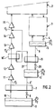
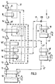
- la figure 1 est une vue schématique d'une installation de réfrigération incorporant un premier mode de réalisation du circuit de compression selon l'invention ;
- la figure 2 est une vue analogue à la précédente illustrant un deuxième mode de réalisation de l'invention, et
- la figure 3 est une vue analogue aux précédentes illustrant un troisième mode de réalisation de l'invention.
- Dans la description qui va suivre et sur les dessins, les éléments identiques ou analogues portent les mêmes chiffres de références, éventuellement indicés.
- On reconnaît sur la figure 1 un cycle de réfrigération hélium comprenant un compresseur de cycle 1, un étage de pré-refroidissement 2, un étage de refroidissement 3 et un organe de détente final 4 délivrant dans une capacité 5 de l'hélium liquide à une pression P₁ de l'ordre de 1,2 x 10⁵ Pa et une température T₁ d'environ 4,4 K. Une telle installation est décrite dans la demande de brevet français FR 90.13280, au nom de la Demanderesse, dont le contenu est supposé intégré ici pour référence. Le liquide dans la capacité 5 est extrait par une ligne 6 pour être refroidi dans un échangeur 7 et détendu dans un organe de détente 8, constitué par une vanne isenthalpique, une turbine ou un détendeur à piston, de façon à délivrer dans une capacité super-froide 9 de l'hélium fluide et gazeux à une température T₂ de l'ordre de 1,75 K et à une pression P₂ de l'ordre de 13 hPa. Le ciel gazeux dans la capacité 9 doit être recomprimé et réchauffé pour être recyclé vers le compresseur de cycle 1.
- A cet effet, une ligne de compression 10 s'étend depuis la capacité 9 jusqu'à l'étage de pré-refroidissement 2 en traversant tout d'abord à contre-courant l'échangeur 7 et en passant dans une série de compresseurs cryogéniques 11 à 15, ici au nombre de cinq. Chaque compresseur a un taux de compression de l'ordre de 3 de façon à ramener la pression de gaz dans la ligne 10, en amont de l'étage de pré-refroidissement 2, à une valeur légèrement supérieure à la pression atmosphérique, de l'ordre de 1,2 x 10⁵ Pa. La température T₃ du gaz en sortie de l'échangeur 7 et à l'entrée du premier étage du compresseur 11 est de l'ordre de 3,5 K et l'on comprend que toutes variations dans les conditions de pression et surtout de température à l'entrée de la chaîne de compression peuvent entraîner des instabilités de fonctionnement dans les étages aval, d'autant que chaque compression entraîne une légère augmentation de la température du gaz. La puissance de compression, donc la taille du compresseur, étant proportionnelle à la température de l'aspiration du compresseur et, pour un débit massique donné, le débit volumique, variant en raison inverse de la température, un refroidissement du gaz entre deux étages de compression présente des avantages notables sur l'optimisation de ces étages de compression et permet de restabiliser au moins une des températures d'entrée d'un inter-étage de compression, ce qui facilite grandement la gestion de la chaîne de compression.
- A cet effet, selon l'invention, un premier échangeur 16 est disposé entre les deuxième et troisième compresseurs 12 et 13, cet échangeur étant refroidi par du liquide prélevé, par une canalisation 17, avantageusement pourvue d'un organe de réglage de débit 170, à partir de la ligne 6, c'est-à-dire à la température T₁ de 4,4 K. Dans le mode de réalisation représenté, la conduite 17 est prolongée pour refroidir, par le gaz vaporisé sortant de l'échangeur 16 à une température de l'ordre de 10 K, un second échangeur 18 interposé entre les quatrième et cinquième compresseurs 14, 15, la conduite 17 étant prolongée pour recycler le gaz prélevé vers le compresseur de cycle 1 au travers de l'étage de pré-refroidissement 2. De cette façon, la température du gaz dans la ligne 10 à l'entrée du troisième compresseur 13 est ramenée et stabilisée à une température T₄ de l'ordre de 5 à 6 K et la température du gaz à l'entrée du cinquième compresseur 15 est ramenée et stabilisée à une température T₅ de l'ordre de 12 K.
- Dans le mode de réalisation de la figure 2, le refroidissement inter-étages de la chaîne de compression est assuré par de l'hélium gazeux provenant d'une capacité additionnelle 5′ où l'hélium bout à une pression réduite. Dans ce mode de réalisation, la canalisation 6 de prélèvement de l'hélium liquide dans la capacité 5 traverse un échangeur 19 pour délivrer, via un organe de détente 20, de l'hélium liquide et gazeux dans la capacité 5′ à une pression P₆ d'environ 0,5 x 10⁵ Pa et une température d'environ 3,5 K. L'hélium liquide dans la capacité 5′ est prélevé par une canalisation 6′ pour être acheminé, via l'échangeur 7 et l'organe de détente 8, comme dans le mode de réalisation précédent, dans la capacité 9 aux pression et température P₂ et T₂.
- Dans ce mode de réalisation, la température de l'hélium liquide dans la conduite 6′ à l'entrée du bout chaud de l'échangeur 7 étant de 3,5 K au lieu de 4,4 K comme dans le mode de réalisation précédent, la température du gaz dans la ligne 10, à la sortie de cet échangeur 7 et à l'entrée du premier étage de compression 11 est ici à une température T′₃ de l'ordre de 2,5 K, ce qui permet de gagner 1 K en amont de la chaîne de compression et donc de gagner encore sur les performances mécaniques et thermodynamiques de la chaîne de compression. Comme dans le mode de réalisation précédent, un échangeur 16′ est intercalé entre les deuxième (12) et troisième (13) étages de compression, cet échangeur 16′ étant ici refroidi par du gaz prélevé dans la capacité 5′ par une conduite 21 traversant tout d'abord l'échangeur 19, puis l'échangeur 16′, de sorte que la température T′₄ du gaz à l'entrée du troisième étage de compression 13 soit ramenée et stabilisée à environ 5 K, la conduite 21 se prolongeant pour réinjecter le gaz réchauffé dans l'échangeur 16′ en amont du compresseur aval 15 de façon à ramener et stabiliser la température d'admission du dernier étage 15 à une valeur T′₅ de l'ordre de 7 K.
- Le mode de réalisation de la figure 3 inclut une combinaison de la variante pilotable exploitant le liquide bouillant à pression sensiblement atmosphérique de la figure 1 et la variante non pilotable mais à stabilité accrue exploitant le liquide bouillant à pression réduite de la figure 2. On reconnaît sur cette figure 3 les éléments des figures 1 et 2 conservant les mêmes chiffres de référence que sur ces dernières. Sur la figure 3, le premier échangeur est décomposé en au moins deux échangeurs 16′, traversé par la conduite 21, et 16, en amont, traversé par les conduites 21 et 17 qui se raccorde, ici, à la ligne 10 en aval du dernier compresseur 15, les deux conduites 17 et 21 traversant en outre un troisième échangeur 22 avantageusement interposé entre les troisième et quatrième compresseurs 13 et 14.
- Le mode de réalisation de la figure 3 comporte en outre, en vue de réduire encore la température d'aspiration du premier étage 11, dans la ligne 6′ en aval de la première capacité additionnelle 5′, une seconde capacité additionnelle 5˝ associée, en amont, comme la première capacité additionnelle 5, à un échangeur 19′ avec un organe de détente intermédiaire 20′. La capacité 5˝ contient ainsi de l'hélium liquide et gazeux à une pression P₇ d'environ 0,15 x 10⁵ Pa et une température d'environ 2,8 K. L'hélium liquide dans la capacité 5˝ est prélevé par une canalisation 6˝ pour être acheminé à l'échangeur 7 et à la capacité 9 aux pression et température P₂ et T₂. L'hélium gazeux dans la capacité 5˝ est acheminé par une conduite 21′ vers les échangeurs 16′ et 16, via un troisième premier échangeur 16˝, puis vers la ligne 10, en amont du quatrième compresseur 14.
- Dans cette variante, on peut utiliser, selon les besoins soit uniquement les circuits mettant en oeuvre les capacités additionnelles 5′ et 5˝, soit simultanément ces circuits et le circuit pilotable mettant en oeuvre la ligne d'hélium liquide 17, ce qui offre ainsi une grande latitude de plages de fonctionnements pour la ligne de compresseurs 10.
- Quoique la présente invention ait été décrite en relation avec des modes de réalisation particuliers, elle ne s'en trouve pas limitée mais est au contraire susceptible de modifications et de variantes qui apparaîtront à l'homme de l'art. En particulier, selon les besoins et les matériels disponibles, on peut diminuer ou augmenter le nombre d'étages de compression et les échangeurs inter-étages.
Claims (12)
- Circuit de compression d'un fluide gazeux à basse pression et basse température provenant d'une première capacité (9) contenant le fluide en phase liquide et en phase gazeuse à une première pression (P₂) et une première température (T₂), comprenant, dans une ligne (10) reliant la première capacité à un réchauffeur (2), au moins deux compresseurs en série (11-15), la première capacité (9) étant alimentée par une seconde capacité (5;5′;5˝) contenant le fluide en phase liquide et en phase gazeuse à une seconde pression (P₁;P₆;P₇) et une seconde température (T₁;T₆;T₇) supérieures aux premières pression et température, caractérisé en ce qu'il comprend, entre les deux compresseurs, au moins un premier échangeur (16;16′;16˝) refroidi par du fluide provenant de la seconde capacité (5;5′; 5˝).
- Circuit selon la revendication 1, caractérisé en ce que le premier échangeur (16) est refroidi (6,17) par la phase liquide de la seconde capacité (5).
- Circuit selon la revendication 2, caractérisé en ce qu'il comprend au moins trois compresseurs et au moins un second échangeur (18) entre deux compresseurs aval (14,15), le second échangeur étant refroidi par la phase gazeuse issue du premier échangeur (16).
- Circuit selon l'une des revendications 1 à 3, caractérisé en ce que le premier échangeur (16′;16˝) est refroidi (21) par la phase gazeuse de la seconde capacité (5′;5˝).
- Circuit selon la revendication 4, caractérisé en ce qu'il comprend au moins trois compresseurs, la phase gazeuse provenant de la seconde capacité (5′;5˝) et réchauffée dans le premier échangeur (16′) étant réinjectée en amont d'un compresseur aval (15;14).
- Circuit selon l'une des revendications 1 à 5, caractérisé en ce que la seconde capacité (5′;5˝) est alimentée par une troisième capacité (5;5′).
- Circuit selon la revendication 6, caractérisé en ce que le fluide en phase gazeuse dans la troisième capacité (5′) refroidit au moins le premier échangeur (16˝)
- Circuit selon l'une des revendications précédentes, caractérisé en ce que le fluide dans la première capacité (9) est de l'hélium à une pression (P₂) inférieure à 20 hPa et une température (T₂) inférieure à 4,2 K.
- Circuit selon la revendication 2 et la revendication 8, caractérisé en ce que la seconde capacité (5) est la capacité d'un cycle de réfrigération hélium contenant de l'hélium liquide à une pression (P₁) d'environ 1,2 x 10⁵ Pa et une température (T₁) d'environ 4,4 K.
- Circuit selon la revendication 4 et la revendication 8, caractérisé en ce que la seconde capacité (5′) contient de l'hélium liquide et gazeux à une pression (P₆) d'environ 0,5 x 10⁵ Pa et une température (T₆) supérieure à 3 K.
- Circuit selon la revendication 10, caractérisé en ce que la seconde capacité (5′) est alimentée par une capacité (5) d'un cycle de réfrigération hélium contenant de l'hélium liquide à une pression (P₁) d'environ 1,2 x 10⁵ Pa et une température (T₁) d'environ 4,4 K.
- Circuit selon l'une des revendications 8 à 11, caractérisé en ce que la première capacité (9) est alimentée en hélium liquide par la seconde capacité (5;5′;5˝) via un échangeur (7) et un organe de détente (8).
Applications Claiming Priority (2)
| Application Number | Priority Date | Filing Date | Title |
|---|---|---|---|
| FR9109482A FR2679635B1 (fr) | 1991-07-26 | 1991-07-26 | Circuit de compression d'un fluide gazeux a basse pression et a basse temperature. |
| FR9109482 | 1991-07-26 |
Publications (2)
| Publication Number | Publication Date |
|---|---|
| EP0526320A1 true EP0526320A1 (fr) | 1993-02-03 |
| EP0526320B1 EP0526320B1 (fr) | 1995-03-01 |
Family
ID=9415572
Family Applications (1)
| Application Number | Title | Priority Date | Filing Date |
|---|---|---|---|
| EP92402160A Expired - Lifetime EP0526320B1 (fr) | 1991-07-26 | 1992-07-27 | Circuit de compression d'un fluide gazeux à basse pression et à basse température |
Country Status (5)
| Country | Link |
|---|---|
| US (1) | US5265426A (fr) |
| EP (1) | EP0526320B1 (fr) |
| JP (1) | JPH05215421A (fr) |
| DE (1) | DE69201541T2 (fr) |
| FR (1) | FR2679635B1 (fr) |
Families Citing this family (10)
| Publication number | Priority date | Publication date | Assignee | Title |
|---|---|---|---|---|
| FR2708093B1 (fr) * | 1993-07-23 | 1995-09-01 | Air Liquide | Installation de réfrigération à très basse température. |
| FR2760074B1 (fr) * | 1997-02-24 | 1999-04-23 | Air Liquide | Procede de compression d'un gaz a basse temperature et a basse pression, ligne de compression et installation de refrigeration correspondantes |
| FR2775518B1 (fr) * | 1998-03-02 | 2000-05-05 | Air Liquide | Procede et installation de production frigorifique a partir d'un cycle thermique d'un fluide a bas point d'ebullition |
| FR2840060B1 (fr) | 2002-05-24 | 2004-07-02 | Air Liquide | Procede et installation de pilotage d'au moins un compresseur centrifuge cryogenique, ligne de compression et installation de refrigeration correspondantes |
| US7409834B1 (en) * | 2005-03-10 | 2008-08-12 | Jefferson Science Associates Llc | Helium process cycle |
| US7278280B1 (en) * | 2005-03-10 | 2007-10-09 | Jefferson Science Associates, Llc | Helium process cycle |
| JP2008109035A (ja) * | 2006-10-27 | 2008-05-08 | Hitachi Ltd | 加圧超流動ヘリウムクライオスタット |
| WO2008079129A1 (fr) * | 2006-12-26 | 2008-07-03 | Carrier Corporation | Système de réfrigération équipé d'un économiseur, d'un refroidisseur intermédiaire et d'un compresseur à plusieurs étages |
| FR2924205B1 (fr) * | 2007-11-23 | 2013-08-16 | Air Liquide | Dispositif et procede de refrigeration cryogenique |
| FR3149678B1 (fr) * | 2023-06-12 | 2025-10-31 | Air Liquide | Installation et un procédé de réfrigération d’un fluide à température cryogénique |
Citations (2)
| Publication number | Priority date | Publication date | Assignee | Title |
|---|---|---|---|---|
| US3092976A (en) * | 1960-08-03 | 1963-06-11 | Conch Int Methane Ltd | Refrigeration of one fluid by heat exchange with another |
| US4910972A (en) * | 1988-12-23 | 1990-03-27 | General Electric Company | Refrigerator system with dual evaporators for household refrigerators |
Family Cites Families (4)
| Publication number | Priority date | Publication date | Assignee | Title |
|---|---|---|---|---|
| GB1135871A (en) * | 1965-06-29 | 1968-12-04 | Air Prod & Chem | Liquefaction of natural gas |
| US4267701A (en) * | 1979-11-09 | 1981-05-19 | Helix Technology Corporation | Helium liquefaction plant |
| SU1086319A1 (ru) * | 1980-09-08 | 1984-04-15 | Всесоюзный научно-исследовательский институт гелиевой техники | Расширительное устройство дл получени холода |
| GB8418840D0 (en) * | 1984-07-24 | 1984-08-30 | Boc Group Plc | Gas refrigeration |
-
1991
- 1991-07-26 FR FR9109482A patent/FR2679635B1/fr not_active Expired - Fee Related
-
1992
- 1992-07-21 JP JP4193701A patent/JPH05215421A/ja active Pending
- 1992-07-24 US US07/918,020 patent/US5265426A/en not_active Expired - Fee Related
- 1992-07-27 EP EP92402160A patent/EP0526320B1/fr not_active Expired - Lifetime
- 1992-07-27 DE DE69201541T patent/DE69201541T2/de not_active Expired - Fee Related
Patent Citations (2)
| Publication number | Priority date | Publication date | Assignee | Title |
|---|---|---|---|---|
| US3092976A (en) * | 1960-08-03 | 1963-06-11 | Conch Int Methane Ltd | Refrigeration of one fluid by heat exchange with another |
| US4910972A (en) * | 1988-12-23 | 1990-03-27 | General Electric Company | Refrigerator system with dual evaporators for household refrigerators |
Also Published As
| Publication number | Publication date |
|---|---|
| DE69201541D1 (de) | 1995-04-06 |
| EP0526320B1 (fr) | 1995-03-01 |
| FR2679635A1 (fr) | 1993-01-29 |
| US5265426A (en) | 1993-11-30 |
| DE69201541T2 (de) | 1995-07-13 |
| JPH05215421A (ja) | 1993-08-24 |
| FR2679635B1 (fr) | 1993-10-15 |
Similar Documents
| Publication | Publication Date | Title |
|---|---|---|
| EP0526320B1 (fr) | Circuit de compression d'un fluide gazeux à basse pression et à basse température | |
| EP4107450B1 (fr) | Dispositif et procédé de réfrigération à dilution | |
| EP2185873B1 (fr) | Procédé de réfrigération cryogénique d'un fluide, par exemple d'hélium, destiné à alimenter un consommateur de fluide, ainsi qu'à une installation correspondante | |
| EP0024962A1 (fr) | Procédé cryogénique de séparation d'air avec production d'oxygène sous haute pression | |
| FR3000541A1 (fr) | Dispositif de refrigeration et/ou de liquefaction et procede correspondant | |
| EP2936006B1 (fr) | Dispositif de réfrigération et/ou de liquéfaction et procédé correspondant | |
| EP2827068B1 (fr) | Pompe à chaleur en cascade | |
| WO2023088607A1 (fr) | Système de pompage cryogénique et intégration innovante pour la cryogénie sub kelvin inférieure à 1,5k | |
| FR2479846A1 (fr) | Procede de refrigeration, pour la recuperation ou le fractionnement d'un melange compose principalement de butane et propane, contenu dans un gaz brut, par utilisation d'un cycle mecanique exterieur | |
| FR2775518A1 (fr) | Procede et installation de production frigorifique a partir d'un cycle thermique d'un fluide a bas point d'ebullition | |
| EP3077736B1 (fr) | Procédé de réfrigération, boîte froide et installation cryogénique correspondantes | |
| CH683287A5 (fr) | Installation de réfrigération. | |
| EP2758725B1 (fr) | Procede et installation de refrigeration | |
| FR2760074A1 (fr) | Procede de compression d'un gaz a basse temperature et a basse pression, ligne de compression et installation de refrigeration correspondantes | |
| WO2019073132A1 (fr) | Procede et appareil de separation d'air par distillation cryogenique | |
| EP2444759B1 (fr) | Procédé et dispositif de refroidissement/liquéfaction à basse température | |
| FR3148082A3 (fr) | Dispositif de refroidissement pour installation de liquéfaction de gaz | |
| FR3167199A3 (fr) | Installation et procédé de réfrigération d’un flux de fluide. | |
| EP4686900A1 (fr) | Procédé et appareil de séparation d'un mélange gazeux | |
| WO2024153378A1 (fr) | Installation et procédé de liquéfaction d'un flux de fluide | |
| EP4463662A1 (fr) | Dispositif et procédé de réchauffement puis détente d'un gaz | |
| WO2023180391A1 (fr) | Procédé de liquéfaction d'un gaz d'alimentation riche en méthane, et installation correspondante | |
| FR3079918A1 (fr) | Dispositif reversible de recuperation d'energie calorifique. | |
| FR2967761A1 (fr) | Module d'echange thermique, installation de production de froid et/ou de chaud comprenant ledit module, et procede de production de froid et/ou de chaud a partir de ladite installation |
Legal Events
| Date | Code | Title | Description |
|---|---|---|---|
| PUAI | Public reference made under article 153(3) epc to a published international application that has entered the european phase |
Free format text: ORIGINAL CODE: 0009012 |
|
| 17P | Request for examination filed |
Effective date: 19920730 |
|
| AK | Designated contracting states |
Kind code of ref document: A1 Designated state(s): CH DE FR GB LI NL |
|
| 17Q | First examination report despatched |
Effective date: 19940526 |
|
| GRAA | (expected) grant |
Free format text: ORIGINAL CODE: 0009210 |
|
| AK | Designated contracting states |
Kind code of ref document: B1 Designated state(s): CH DE FR GB LI NL |
|
| GBT | Gb: translation of ep patent filed (gb section 77(6)(a)/1977) |
Effective date: 19950228 |
|
| REF | Corresponds to: |
Ref document number: 69201541 Country of ref document: DE Date of ref document: 19950406 |
|
| PLBE | No opposition filed within time limit |
Free format text: ORIGINAL CODE: 0009261 |
|
| STAA | Information on the status of an ep patent application or granted ep patent |
Free format text: STATUS: NO OPPOSITION FILED WITHIN TIME LIMIT |
|
| 26N | No opposition filed | ||
| PGFP | Annual fee paid to national office [announced via postgrant information from national office to epo] |
Ref country code: GB Payment date: 20010615 Year of fee payment: 10 |
|
| PGFP | Annual fee paid to national office [announced via postgrant information from national office to epo] |
Ref country code: NL Payment date: 20010619 Year of fee payment: 10 |
|
| REG | Reference to a national code |
Ref country code: GB Ref legal event code: IF02 |
|
| PGFP | Annual fee paid to national office [announced via postgrant information from national office to epo] |
Ref country code: FR Payment date: 20020610 Year of fee payment: 11 |
|
| PGFP | Annual fee paid to national office [announced via postgrant information from national office to epo] |
Ref country code: CH Payment date: 20020617 Year of fee payment: 11 |
|
| PGFP | Annual fee paid to national office [announced via postgrant information from national office to epo] |
Ref country code: DE Payment date: 20020619 Year of fee payment: 11 |
|
| PG25 | Lapsed in a contracting state [announced via postgrant information from national office to epo] |
Ref country code: GB Free format text: LAPSE BECAUSE OF NON-PAYMENT OF DUE FEES Effective date: 20020727 |
|
| PG25 | Lapsed in a contracting state [announced via postgrant information from national office to epo] |
Ref country code: NL Free format text: LAPSE BECAUSE OF NON-PAYMENT OF DUE FEES Effective date: 20030201 |
|
| GBPC | Gb: european patent ceased through non-payment of renewal fee |
Effective date: 20020727 |
|
| NLV4 | Nl: lapsed or anulled due to non-payment of the annual fee |
Effective date: 20030201 |
|
| PG25 | Lapsed in a contracting state [announced via postgrant information from national office to epo] |
Ref country code: LI Free format text: LAPSE BECAUSE OF NON-PAYMENT OF DUE FEES Effective date: 20030731 Ref country code: CH Free format text: LAPSE BECAUSE OF NON-PAYMENT OF DUE FEES Effective date: 20030731 |
|
| PG25 | Lapsed in a contracting state [announced via postgrant information from national office to epo] |
Ref country code: DE Free format text: LAPSE BECAUSE OF NON-PAYMENT OF DUE FEES Effective date: 20040203 |
|
| REG | Reference to a national code |
Ref country code: CH Ref legal event code: PL |
|
| PG25 | Lapsed in a contracting state [announced via postgrant information from national office to epo] |
Ref country code: FR Free format text: LAPSE BECAUSE OF NON-PAYMENT OF DUE FEES Effective date: 20040331 |
|
| REG | Reference to a national code |
Ref country code: FR Ref legal event code: ST |