EP0526363A2 - Biegsame Verbundisolationsdecke - Google Patents
Biegsame Verbundisolationsdecke Download PDFInfo
- Publication number
- EP0526363A2 EP0526363A2 EP92420261A EP92420261A EP0526363A2 EP 0526363 A2 EP0526363 A2 EP 0526363A2 EP 92420261 A EP92420261 A EP 92420261A EP 92420261 A EP92420261 A EP 92420261A EP 0526363 A2 EP0526363 A2 EP 0526363A2
- Authority
- EP
- European Patent Office
- Prior art keywords
- insulation
- fabric
- blanket
- honeycomb
- silicon carbide
- Prior art date
- Legal status (The legal status is an assumption and is not a legal conclusion. Google has not performed a legal analysis and makes no representation as to the accuracy of the status listed.)
- Withdrawn
Links
Images




Classifications
-
- B—PERFORMING OPERATIONS; TRANSPORTING
- B32—LAYERED PRODUCTS
- B32B—LAYERED PRODUCTS, i.e. PRODUCTS BUILT-UP OF STRATA OF FLAT OR NON-FLAT, e.g. CELLULAR OR HONEYCOMB, FORM
- B32B3/00—Layered products comprising a layer with external or internal discontinuities or unevennesses, or a layer of non-planar shape; Layered products comprising a layer having particular features of form
- B32B3/10—Layered products comprising a layer with external or internal discontinuities or unevennesses, or a layer of non-planar shape; Layered products comprising a layer having particular features of form characterised by a discontinuous layer, i.e. formed of separate pieces of material
- B32B3/12—Layered products comprising a layer with external or internal discontinuities or unevennesses, or a layer of non-planar shape; Layered products comprising a layer having particular features of form characterised by a discontinuous layer, i.e. formed of separate pieces of material characterised by a layer of regularly- arranged cells, e.g. a honeycomb structure
-
- B—PERFORMING OPERATIONS; TRANSPORTING
- B32—LAYERED PRODUCTS
- B32B—LAYERED PRODUCTS, i.e. PRODUCTS BUILT-UP OF STRATA OF FLAT OR NON-FLAT, e.g. CELLULAR OR HONEYCOMB, FORM
- B32B27/00—Layered products comprising a layer of synthetic resin
- B32B27/06—Layered products comprising a layer of synthetic resin as the main or only constituent of a layer, which is next to another layer of the same or of a different material
- B32B27/08—Layered products comprising a layer of synthetic resin as the main or only constituent of a layer, which is next to another layer of the same or of a different material of synthetic resin
-
- B—PERFORMING OPERATIONS; TRANSPORTING
- B32—LAYERED PRODUCTS
- B32B—LAYERED PRODUCTS, i.e. PRODUCTS BUILT-UP OF STRATA OF FLAT OR NON-FLAT, e.g. CELLULAR OR HONEYCOMB, FORM
- B32B27/00—Layered products comprising a layer of synthetic resin
- B32B27/12—Layered products comprising a layer of synthetic resin next to a fibrous or filamentary layer
-
- B—PERFORMING OPERATIONS; TRANSPORTING
- B32—LAYERED PRODUCTS
- B32B—LAYERED PRODUCTS, i.e. PRODUCTS BUILT-UP OF STRATA OF FLAT OR NON-FLAT, e.g. CELLULAR OR HONEYCOMB, FORM
- B32B27/00—Layered products comprising a layer of synthetic resin
- B32B27/28—Layered products comprising a layer of synthetic resin comprising synthetic resins not wholly covered by any one of the sub-groups B32B27/30 - B32B27/42
- B32B27/281—Layered products comprising a layer of synthetic resin comprising synthetic resins not wholly covered by any one of the sub-groups B32B27/30 - B32B27/42 comprising polyimides
-
- B—PERFORMING OPERATIONS; TRANSPORTING
- B32—LAYERED PRODUCTS
- B32B—LAYERED PRODUCTS, i.e. PRODUCTS BUILT-UP OF STRATA OF FLAT OR NON-FLAT, e.g. CELLULAR OR HONEYCOMB, FORM
- B32B27/00—Layered products comprising a layer of synthetic resin
- B32B27/28—Layered products comprising a layer of synthetic resin comprising synthetic resins not wholly covered by any one of the sub-groups B32B27/30 - B32B27/42
- B32B27/285—Layered products comprising a layer of synthetic resin comprising synthetic resins not wholly covered by any one of the sub-groups B32B27/30 - B32B27/42 comprising polyethers
-
- B—PERFORMING OPERATIONS; TRANSPORTING
- B32—LAYERED PRODUCTS
- B32B—LAYERED PRODUCTS, i.e. PRODUCTS BUILT-UP OF STRATA OF FLAT OR NON-FLAT, e.g. CELLULAR OR HONEYCOMB, FORM
- B32B27/00—Layered products comprising a layer of synthetic resin
- B32B27/30—Layered products comprising a layer of synthetic resin comprising vinyl (co)polymers; comprising acrylic (co)polymers
- B32B27/304—Layered products comprising a layer of synthetic resin comprising vinyl (co)polymers; comprising acrylic (co)polymers comprising vinyl halide (co)polymers, e.g. PVC, PVDC, PVF, PVDF
-
- B—PERFORMING OPERATIONS; TRANSPORTING
- B32—LAYERED PRODUCTS
- B32B—LAYERED PRODUCTS, i.e. PRODUCTS BUILT-UP OF STRATA OF FLAT OR NON-FLAT, e.g. CELLULAR OR HONEYCOMB, FORM
- B32B5/00—Layered products characterised by the non- homogeneity or physical structure, i.e. comprising a fibrous, filamentary, particulate or foam layer; Layered products characterised by having a layer differing constitutionally or physically in different parts
- B32B5/22—Layered products characterised by the non- homogeneity or physical structure, i.e. comprising a fibrous, filamentary, particulate or foam layer; Layered products characterised by having a layer differing constitutionally or physically in different parts characterised by the presence of two or more layers which are next to each other and are fibrous, filamentary, formed of particles or foamed
- B32B5/24—Layered products characterised by the non- homogeneity or physical structure, i.e. comprising a fibrous, filamentary, particulate or foam layer; Layered products characterised by having a layer differing constitutionally or physically in different parts characterised by the presence of two or more layers which are next to each other and are fibrous, filamentary, formed of particles or foamed one layer being a fibrous or filamentary layer
- B32B5/26—Layered products characterised by the non- homogeneity or physical structure, i.e. comprising a fibrous, filamentary, particulate or foam layer; Layered products characterised by having a layer differing constitutionally or physically in different parts characterised by the presence of two or more layers which are next to each other and are fibrous, filamentary, formed of particles or foamed one layer being a fibrous or filamentary layer another layer next to it also being fibrous or filamentary
-
- B—PERFORMING OPERATIONS; TRANSPORTING
- B64—AIRCRAFT; AVIATION; COSMONAUTICS
- B64G—COSMONAUTICS; VEHICLES OR EQUIPMENT THEREFOR
- B64G1/00—Cosmonautic vehicles
- B64G1/22—Parts of, or equipment specially adapted for fitting in or to, cosmonautic vehicles
- B64G1/52—Protection, safety or emergency devices; Survival aids
- B64G1/58—Thermal protection, e.g. heat shields
-
- D—TEXTILES; PAPER
- D02—YARNS; MECHANICAL FINISHING OF YARNS OR ROPES; WARPING OR BEAMING
- D02G—CRIMPING OR CURLING FIBRES, FILAMENTS, THREADS, OR YARNS; YARNS OR THREADS
- D02G3/00—Yarns or threads, e.g. fancy yarns; Processes or apparatus for the production thereof, not otherwise provided for
- D02G3/44—Yarns or threads characterised by the purpose for which they are designed
- D02G3/46—Sewing-cottons or the like
-
- F—MECHANICAL ENGINEERING; LIGHTING; HEATING; WEAPONS; BLASTING
- F16—ENGINEERING ELEMENTS AND UNITS; GENERAL MEASURES FOR PRODUCING AND MAINTAINING EFFECTIVE FUNCTIONING OF MACHINES OR INSTALLATIONS; THERMAL INSULATION IN GENERAL
- F16L—PIPES; JOINTS OR FITTINGS FOR PIPES; SUPPORTS FOR PIPES, CABLES OR PROTECTIVE TUBING; MEANS FOR THERMAL INSULATION IN GENERAL
- F16L59/00—Thermal insulation in general
- F16L59/02—Shape or form of insulating materials, with or without coverings integral with the insulating materials
- F16L59/026—Mattresses, mats, blankets or the like
-
- B—PERFORMING OPERATIONS; TRANSPORTING
- B32—LAYERED PRODUCTS
- B32B—LAYERED PRODUCTS, i.e. PRODUCTS BUILT-UP OF STRATA OF FLAT OR NON-FLAT, e.g. CELLULAR OR HONEYCOMB, FORM
- B32B2305/00—Condition, form or state of the layers or laminate
- B32B2305/02—Cellular or porous
- B32B2305/024—Honeycomb
-
- B—PERFORMING OPERATIONS; TRANSPORTING
- B64—AIRCRAFT; AVIATION; COSMONAUTICS
- B64G—COSMONAUTICS; VEHICLES OR EQUIPMENT THEREFOR
- B64G1/00—Cosmonautic vehicles
- B64G1/22—Parts of, or equipment specially adapted for fitting in or to, cosmonautic vehicles
- B64G1/46—Arrangements or adaptations of devices for control of environment or living conditions
- B64G1/50—Arrangements or adaptations of devices for control of environment or living conditions for temperature control
- B64G1/503—Radiator panels
-
- Y—GENERAL TAGGING OF NEW TECHNOLOGICAL DEVELOPMENTS; GENERAL TAGGING OF CROSS-SECTIONAL TECHNOLOGIES SPANNING OVER SEVERAL SECTIONS OF THE IPC; TECHNICAL SUBJECTS COVERED BY FORMER USPC CROSS-REFERENCE ART COLLECTIONS [XRACs] AND DIGESTS
- Y10—TECHNICAL SUBJECTS COVERED BY FORMER USPC
- Y10S—TECHNICAL SUBJECTS COVERED BY FORMER USPC CROSS-REFERENCE ART COLLECTIONS [XRACs] AND DIGESTS
- Y10S428/00—Stock material or miscellaneous articles
- Y10S428/92—Fire or heat protection feature
-
- Y—GENERAL TAGGING OF NEW TECHNOLOGICAL DEVELOPMENTS; GENERAL TAGGING OF CROSS-SECTIONAL TECHNOLOGIES SPANNING OVER SEVERAL SECTIONS OF THE IPC; TECHNICAL SUBJECTS COVERED BY FORMER USPC CROSS-REFERENCE ART COLLECTIONS [XRACs] AND DIGESTS
- Y10—TECHNICAL SUBJECTS COVERED BY FORMER USPC
- Y10T—TECHNICAL SUBJECTS COVERED BY FORMER US CLASSIFICATION
- Y10T428/00—Stock material or miscellaneous articles
- Y10T428/24—Structurally defined web or sheet [e.g., overall dimension, etc.]
- Y10T428/24149—Honeycomb-like
-
- Y—GENERAL TAGGING OF NEW TECHNOLOGICAL DEVELOPMENTS; GENERAL TAGGING OF CROSS-SECTIONAL TECHNOLOGIES SPANNING OVER SEVERAL SECTIONS OF THE IPC; TECHNICAL SUBJECTS COVERED BY FORMER USPC CROSS-REFERENCE ART COLLECTIONS [XRACs] AND DIGESTS
- Y10—TECHNICAL SUBJECTS COVERED BY FORMER USPC
- Y10T—TECHNICAL SUBJECTS COVERED BY FORMER US CLASSIFICATION
- Y10T428/00—Stock material or miscellaneous articles
- Y10T428/26—Web or sheet containing structurally defined element or component, the element or component having a specified physical dimension
-
- Y—GENERAL TAGGING OF NEW TECHNOLOGICAL DEVELOPMENTS; GENERAL TAGGING OF CROSS-SECTIONAL TECHNOLOGIES SPANNING OVER SEVERAL SECTIONS OF THE IPC; TECHNICAL SUBJECTS COVERED BY FORMER USPC CROSS-REFERENCE ART COLLECTIONS [XRACs] AND DIGESTS
- Y10—TECHNICAL SUBJECTS COVERED BY FORMER USPC
- Y10T—TECHNICAL SUBJECTS COVERED BY FORMER US CLASSIFICATION
- Y10T428/00—Stock material or miscellaneous articles
- Y10T428/27—Web or sheet containing structurally defined element or component, the element or component having a specified weight per unit area [e.g., gms/sq cm, lbs/sq ft, etc.]
-
- Y—GENERAL TAGGING OF NEW TECHNOLOGICAL DEVELOPMENTS; GENERAL TAGGING OF CROSS-SECTIONAL TECHNOLOGIES SPANNING OVER SEVERAL SECTIONS OF THE IPC; TECHNICAL SUBJECTS COVERED BY FORMER USPC CROSS-REFERENCE ART COLLECTIONS [XRACs] AND DIGESTS
- Y10—TECHNICAL SUBJECTS COVERED BY FORMER USPC
- Y10T—TECHNICAL SUBJECTS COVERED BY FORMER US CLASSIFICATION
- Y10T442/00—Fabric [woven, knitted, or nonwoven textile or cloth, etc.]
- Y10T442/30—Woven fabric [i.e., woven strand or strip material]
- Y10T442/3179—Woven fabric is characterized by a particular or differential weave other than fabric in which the strand denier or warp/weft pick count is specified
- Y10T442/3195—Three-dimensional weave [e.g., x-y-z planes, multi-planar warps and/or wefts, etc.]
- Y10T442/3211—Multi-planar weft layers
Definitions
- the present invention relates to a new and improved composite flexible blanket insulation (CFBI) useful as a thermal protection system for specific heating environments which contain conductive, convective and radiative heating components.
- this invention relates to CFBI comprising essentially of interlocked silicon carbide fabric and multiple alternating layers of single aluminized foil and/or honeycomb patterned foil.
- the blanket has high emissivity and resistance to a high heat flux and thermal insulation capability between 1450°C and 1650°C.
- the new CFBI contains three improvements: honeycomb patterned radiation shield or spacer, single-side aluminized foil radiation shield and a new interlock silicon carbide fabric. Individually and particularly when combined, these improvements result in substantial weight saving, lower thermal diffusivity and/or conductivity and high density surface which assures the high emissivity of the CFBI.
- Aerospace vehicles are subject to aeroconvective and radiative heating, launch acoustics and rain during atmospheric entry and consequently require extremely efficient thermal protection as described in systems capable of protecting their metal or composite substructures from reaching temperatures above their operating limit.
- AFRSI Advanced Flexible Reusable Surface Insulation
- AFRSI insulation is a quilt-like material made of two layers of silica and glass cloth interspaced with one layer of fibrous silica felt, sewn together with silica and glass threads.
- the AFRSI has a thickness between 1-5 cm and a temperature capability in excess of 650°C.
- TABI Tailorable Advanced Blanket Insulation
- MLA blanket multilayer insulation blanket, which has a much lower thermal conductivity.
- This MLA blanket is commonly used for thermal control within spacecraft.
- an all ceramic fibrous insulation such as the AFRSI or TABI, much lower effective thermal conductivities can be achieved.
- This insulation consists of ceramic alumino borosilicate fabrics used for top and bottom surfaces, silica, aluminoborosilicate (ABS) or alumina insulations, and multilayers of stainless steel foils separated by ABS scrim, all quilted together using ceramic thread.
- SiC fabric surfaces can survive higher heating loads than silica fabric. For example, exposure to a heating rate of 37 W/cm2 resulted in no observable deterioration of the SiC fabric surface, whereas a silica fabric became brittle after exposure to 10 W/cm2.
- the higher emissivity of SiC over silica was found to be another advantage for high-temperature environments.
- the current invention represents substantial improvement of the CFBI as described in the 07/410,576 patent application.
- the main improvements concern the aluminumization and the pattern of the foil and the new design of silicon carbide fabric. It has been now found that single-side aluminized foils exhibit lower thermal conductivity than double-side aluminized foils, that the honeycomb technology used for aluminum foil instead of flat foil has lower thermal diffusivity and conductivity and provides substantial weight savings, and that certain new design of silicon carbide fabric has higher emittance than other silicon carbide fabrics.
- honeycomb technology is described in the U.S. patent 4,550,046, incorporated herein by reference. That patent discloses an insulating material made of one or more layers of open ended cells formed from flexible thin plastic sheets.
- honeycomb insulation was first used around the turn of the century in early solar water heaters. Since then, many applications have been considered but certain limitations have prohibited its widespread use, including production cost, mechanical problems of application and limitations on materials used in honeycomb construction.
- honeycomb technology for aluminum foil such as aluminized Kapton foil (Al Kapton), and incorporation of such honeycomb-like patterned aluminized foil in multilayered insulation materials have not been previously described or suggested.
- the new blanket has thermal insulation capability well above those insulations known and used until now and provides at the same time, the substantial weight savings.
- the new blanket is suitable for use in the spacecraft industry, for furnace curtains, fire tools and equipment or for any other use where the temperature capability, the insulation efficiency and weight are all equally important.
- One aspect of this invention is a lightweight, composite, multilayered, flexible, durable and reusable multilayer blanket insulation consisting of top and bottom layers of silicon carbide fabric, one or both of which have a new interlock design, of insulation layers, of multilayer area made of reflecting radiation shield layers of single or double aluminized polyimide or metallic film on a polymeric substrate, or a honeycomb metal foil made of the same material as the shield alternating with aluminoborosilicate scrim, felt or polyimide film or other suitable spacer, all these layers sewn together into a quilt-like blanket with high temperature withstanding ceramic thread.
- Another aspect of this invention is an insulation blanket having a thermal insulating capability for temperatures up to 1650°C on the hot exterior surface wherein the current improvements result in low backface temperature, in substantial weight savings, in lower thermal diffusivity or conductivity and the surface density is significantly higher than those state of the art insulations, thus assuring the higher emissivity of the new blanket.
- Still yet another aspect of this invention is a composite flexible blanket insulation wherein the foil is aluminized Kapton honeycomb foil.
- Still another aspect of this invention is a composite flexible blanket insulation wherein the aluminized foil is Kapton aluminized on one side only.
- Yet another aspect of this invention is the insulation blanket of which outer surface (top) is silicon carbide fabric having interlock design and the inner backface (bottom) fabric can be ABS or silica.
- Fig. 1 is a perspective view of a configuration of CFBI multilayer and composite insulations of this invention.
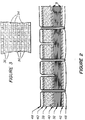
- Fig. 2 is a side cross-sectional view of the multilayered insulation blanket.
- Fig. 3 is an enlarged cut out portion of the insulation of Fig. 2, showing the alternating layers of honeycomb metal foil and spacer.
- Fig. 4 is a perspective overview of completed quilted insulation blanket configuration.
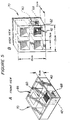
- Fig. 5 is a thermal diffusivity sample holder front view (5A) and back view (5B) with test sample in position.
- Fig. 6 depicts a honeycomb foil configuration of cells before (6A) and after (6B) stretch forming.
- Fig. 7 depicts a thermal response of multilayer foil insulations with or without honeycomb foil.
- Fig. 8 depicts an apparent thermal conductivity of CFBI with one and two side aluminized foils.
- Fig. 9 depicts a comparison of weave type interlock three-ply silicon carbide fabric.
- Fig. 10 depicts a comparison of a new silicon carbide and a regular silicon carbide fabrics and the effect of temperature on their total hemispherical emittance.
- nier refers to the number of grams per 9000 m, using a direct yarn numbering system expressing yarn number in terms of mass per unit length.
- Fiber refers to a variety of fiber having an extreme length which are not readily measured.
- Thread refers to a flexible small diameter yarn or strand, usually treated with a surface coating, lubricant or both used to stitch one or more pieces of material.
- Tow refers to a twistless multi-filament strand suitable for conversion into staple fibers or sliver, or for direct spinning into yarn.
- “Yarn” refers to a continuous strand of textile fibers, filaments or materials in a form suitable for knitting, weaving, or otherwise intertwining to form a textile fabric.
- Interlock design or "interlock silicon carbide fabric” refers to silicon carbide fabric having the pattern as shown in Figure 9, and generally it consists of three layers of at least three-ply silicon carbide yarn interlocked in a specific pattern of interweaving one ply with the second and third ply.
- the resulting fabric acquires two very important features compared to the regularly weaved fabric. First, it has a much larger surface which has high density, and second, it has high emissivity.
- “Honeycomb” or “honeycomb technology” refers to a honeycomb-like pattern, as described in U.S. patent 4,550,046, issued on October 29, 1985.
- the composite flexible blanket insulation of the current invention provides an improved lightweight insulation which is extremely effective in terms of thermal protection of structures subjected singly or repeatedly to high heat fluxes.
- the present insulation utilizes the previously known multilayer insulation concept, in particular CFBI, to derive a new lightweight insulation configuration having improved insulation properties at high temperatures and at near vacuum conditions.
- the new insulation blanket is made generally of the same components as CFBI but these components are improved to provide substantial weight savings, substantial decrease in backface temperature, lower thermal conductivity and increased emittance. These improvements are caused partly by newly designed interlock silicon carbide fabric used for the outer surface covers, partly by substituting flat foil aluminized on both sides with foil aluminized on one side only and partly by using the honeycomb pattern instead of the flat foil.
- the new insulation blanket materials are quilted together into an insulation blanket with durable silicon carbide or with other high temperature withstanding ceramic threads.
- Optimal blanket insulation layers configuration, optimal combination of multilayer area (MLA) within the insulation, improved thermal insulation capability and significant weight savings are primary features of this invention.
- CFRP Composite Flexible Blanket Insulation
- a high temperature insulation of this invention utilizing honeycomb technology, similar in construction to a CFBI, provides two additional features/advantages over the use of flat insulation sheets.
- the honeycomb patterned sheets have lower thermal diffusivity/conductivity without increase in weight and provide substantial weight savings over conventional insulations.
- the new CFBI insulation of this invention utilizes honeycomb-like patterned foils which reduce the weight of the CFBI blanket or other insulation material and improve its durability in thermal protection systems able to withstand temperatures around and above 1450°C. When the honeycomb is used in conjunction or combination with an insulation such as CFBI, it reduces the overall thermal diffusivity and thermal conductivity of the system.
- the honeycomb foils singly or two or more stacked together, effectively prevent convection and reduce conduction through the structure.
- the honeycomb patterned materials can be produced from highly reflective, highly absorptive or nearly transparent materials to prevent or allow radiation depending on the heating environment.
- the honeycomb cell dimensions may be designed in such a way as to prevent or allow convection, or to increase or decrease the solid viewing angle through the insulation which impacts radiation.
- the versatility of the honeycomb containing CFBI is unlimited and depends on the degree of stretch introduced, on size and geometry of slits, on material used on number of sheets and on combination of all these together.
- the honeycomb containing CFBI blanket can be tailored with the different types of honeycomb to be an effective insulator for specific heating environments which may contain both convective and radiative heating components.
- Honeycomb technology seen in Figures 6A and 6B generally represents a layer of open ended cells 58 fabricated from a flat, preferably flexible, sheet of thin material 50 into which flat sheet numerous slits 56 are made in a pattern resulting in controlled geometry air cells 58 upon stretching the foil perpendicularly to the axis of the cells as seen in Figure 6B.
- the non-stretched flat sheet 50 of material showing the slits 56 is seen in Figure 6A.
- the stretched, that is expanded material 52 containing expanded slits 56 in a cross-direction of the slits 56, forming open ended cells 58 is seen in Figure 6B.
- the sheet 52 shows the honeycomb-like pattern fabrication containing multiplicity of honeycomb-like cells 58.
- the manufacture of honeycomb-like materials is included in U.S. patent 4,550,046, incorporated herein by reference.
- honeycomb technology is flexible in allowing use of a wide variety of materials, various cell dimensions and numerous combinations of honeycomb and barrier elements.
- honeycomb-like material uses an unusual geometry.
- the process for preparing honeycomb-like pattern involves expanding a previously flat two dimensional sheet of material into a three dimensional structure in such a way that the occupied volume increases substantially.
- This honeycomb pattern can be produced from many non-woven materials including polyimide plastic film, metal foil, aluminized foil, Saran® wrap, Mylar film, ceramic metalized papers such as silica or quartz and any other suitable material.
- the geometry of the honeycomb pattern is unusual because many of the honeycomb walls are angled at 60° instead of vertical as in load bearing honeycomb.
- the preferred material for use in this invention is a polyimide foil aluminized or gold plated on one or both sides, or a metal foil made of aluminum or stainless steel.
- the polyimide foil (DuPont Kapton®), which is particularly preferred, is available in 0.00076 cm thickness, coated on one side or on both sides with 700 to 1000 angstroms vacuum-deposited aluminum from sources such as Sheldahl (Sheldahl, Inc., 1150 Sheldahl Rd., Northfield, MN 55057.)
- the non-woven quartz paper is available in a 0.0127 cm thickness from Pallflex Corporation, Denver, Colorado.
- honeycomb-like patterned material in the fabrication of CFBI results in substantial weight savings.
- the original CFBI insulation uses as spacers scrim elements that weigh approximately 34 g/sq.m.
- the honeycomb patterned alternative material produced from 0.00076 cm thick Kapton would weigh approximately 7.8 g/sq.m. Because at least nine such elements would be used and up to thirty such elements could be used in these insulations, the total weight savings possible by substituting honeycomb foil for scrim would be from 300-800 g/sq.m. Since the honeycomb layers may also be aluminized, the need for reflective foil layers may be reduced or eliminated, providing further weight saving of another 150-400 g/sq.m.
- CFBI blankets were originally designed for thermal insulation of spaceships. The latest improvements are specifically designed for insulation for the Aeroassist Flight Experiment (AFE).
- AFE Aeroassist Flight Experiment
- the total weight of the current blanket designed to limit AFE skin temperature to 176°C would be around 1177 g/sq.m. which provides a total savings of around 1.2 kg/sq.m. compared to prior CFBI and Tailorable Advanced Blanket Insulation.
- honeycomb materials will significantly reduce weight without sacrificing durability. While the most preferable material for insulation of this invention is a polyimide honeycomb, quartz honeycomb able to withstand temperatures to 1950°C, similarly finds wide utility in other atmospheric entry vehicles.
- honeycomb separators would preferably substitute the scrim-cloth or crinkled Kapton currently used in multilayer area (MLA) 32, as seen in Figures 1-4.
- MVA multilayer area
- the flexible honeycomb layers, produced from polymeric or ceramic materials, are more durable than the crinkled Kapton and significantly lighter in weight than scrim.
- honeycomb-like material is quite versatile in its application in various insulation designs. For example, several layers of honeycomb stacked together effectively prevent convection and reduce conduction and radiation with a lightweight homogeneous assembly. If reflective barriers are inserted between some or all of the honeycomb layers, radiation is further reduced and the conductivity decreases substantially. Furthermore, the honeycomb may be selectively produced from highly reflective, highly absorptive or nearly transparent materials to prevent or allow radiation. Lastly, cell dimensions may be varied to prevent or allow convection, or to increase or decrease the solid viewing angle through the insulation which impacts radiation.
- the honeycomb insulation is an improvement in CFBI because it reduces the weight of the multilayer area 32 elements. In Figure 1, the MLA 32, for example, is shown as 10 layers of reflective shield 34 alternating with spacers 36.
- the reflective shield is currently made of stainless steel and the spacer is made of Aluminoborosilicate scrim cloth, by using the honeycomb concept when the scrim is replaced with honeycomb structure, a substantial weight savings is realized. That is even more so when the stainless steel is substituted with Al Kapton aluminized on one side.
- CFBI Blankets consisting of an outer layer of silicon carbide fabric, Alumina (Saffil®) Insulation and Aluminized Kapton Honeycomb foil of various weights were compared with a similar blanket containing flat aluminized Kapton foil.
- the blankets were exposed to the Thermal Diffusivity Apparatus and the thermal response of the composite insulations was determined using a procedure and apparatus described previously in NASA Tech. Brief , 10642 (January 1979).
- the pressure used in the apparatus for testing configurations 1-4 (Table 1) was 1.2-1.5 mm Hg.
- the pressure 1.5 mm Hg simulates the vacuum environment of the various aerospace vehicles.
- the temperature pulse applied to the front surface was between 1000°C and 1200°C.
- the backface temperature was measured for 15-20 minutes.
- the insulation thermal diffusivity or thermal response is generally measured by the increase in backface temperature as a function of time.
- the backface temperature means the temperature measured in the bottom inner mold line fabric 42 after exposure of the front face or the outer mold line fabric 40 surface to high temperature, in this instance to temperatures between 1000°C and 1200°C.
- the test results of backface temperature as seen in Figure 7 are the average of eight test runs from each configuration.
- Backface temperature was measured with an apparatus shown in Figures 5A and 5B.
- Two thermocouples 60 and 62 were used to determine the top 60 and bottom 62 temperatures.
- Furnace control thermocouple was embedded in a black reaction cured glass coating 66 on the top ( Figure 5A) of the thermal diffusivity sample holder 70, shown in Figures 5A and 5B.
- the second calorimetric thermocouple 62 was embedded in the fabric 42 covering the bottom or the backface of the CFBI 30 insulation, as seen in Figure 1.
- FIG. 5A shows the thermal diffusivity sample holder 70 from the front view.
- the sample 68 of CFBI was placed in one of the chambers of the holder 70.
- the top side of the holder has a black coating 66.
- the furnace control thermocouples 60 are embedded which measure temperature to which the outer mold line fabric 40 is subjected.
- the second thermocouple 62 is embedded in the inner mold line fabric 42.
- the temperature measured by the second thermocouple 42 is the backface temperature.
- the backface temperature is commonly used to describe the insulation properties of the material or composite blanket.
- the thermocouple 60 measures the temperature of the furnace 1000°C and the second thermocouple 62 measures only 100°C backface temperatures, the insulation capacity of the tested material is around 90%.
- the backface temperature is 900°C, insulation capacity is only 10% and the insulation properties of the tested material are poor.
- the blankets containing honeycomb foils of lesser weight show the lesser insulation capability than the heavier and thicker blanket, ( ⁇ ), but their insulation capability is still better than that of the flat foil ( ⁇ ).
- Al Kapton honeycomb 0.7 g ( ⁇ ) reaches maximal backface temperature around 120-125°C and the really thin Al Kapton honeycomb (O), having mass and thickness almost 4 times lesser than flat foil, shows the maximal backface temperature around 150°C. All blankets containing honeycomb insulations are thus better than the flat foil insulation ( ⁇ ).
- Table 1 illustrates a composition of MLA of CFBI blankets tested for their thermal response mass and thickness comparing conventional ⁇ and honeycomb ⁇ , ⁇ , and ⁇ MLAs.
- Honeycomb material be it polyimide or quartz
- honeycomb material was produced by creating a continuous pattern of staggered perforations in the web using a matched set of rotary dies.
- a pattern of slits in the foil allows it to expand if stretched lengthwise that is perpendicularly to the axis of the slits. In this way, the occupied volume increased approximately 140%.
- the honeycomb structure can be used to create an efficient thermal insulation as seen from the results.
- the perforated material is expanded to form the honeycomb-like structure.
- Kapton honeycomb is set in place with heat, while quartz honeycomb is set by misting with water.
- honeycomb fabric For testing, eight inch diameter circles are cut from the honeycomb fabric by using a template as a guide. For those specimens requiring flat barriers to block or reflect radiation, eight inch diameter circles are cut from nonperforated aluminized Kapton and quartz as well.
- the honeycomb and barrier elements are next assembled according to the design of the CFBI to be tested. To better block radiation, the honeycomb elements are alternately rotated 90° using the axis of expansion as the reference. Following assembly, the specimens are stored in a plastic bag to await testing. These construction steps and storage are the same for each of the four designs tested.
- the second novel feature of this invention concerns findings that the single side aluminized foils exhibit lower thermal conductivity than the double side aluminized foils. This feature provides a new insulation with extremely low thermal conductivity useful especially in low pressure environments such as used for aerospace applications.
- CFRP composite flexible blanket insulations
- CFBI-1 was made of silicon carbide, alumina, aluminized Kapton on one side, 1.03 inches thick, 8.23-8.38 lb/ft3 density.
- CFBI-2 was made of silicon carbide, alumina, aluminized Kapton on both sides only, 1.03 inch thick, 9.25 - 9.40 lb/ft3 density.
- Tables 2 and 3 list the apparent thermal conductivity and thermal resistance values for the two insulation materials measured.
- Figure 8 presents the apparent thermal conductivity vs. temperature relation for the two materials measured.
- CFBI-1 containing single aluminized Kapton exhibited lower thermal conductivity than double CFBI-2 at all test conditions.
- CFBI-1 Single Aluminized Kapton
- CFBI-2 Double Aluminized Kapton
- W/(mK) apparent thermal conductivity
- their apparent conductivities and thermal resistance differ. While the apparent conductivity of the CFBI-1 increases at 1 ATM only slightly from 0.051 at 200°C to 0.59 at 400°C, it increases substantially from 0.049 at 200°C to 0.084 at 400°C for CFBI-2.
- Silicon carbide fabric has previously been found to provide certain advantages when used as top and bottom cover layers of the CFBI. Recently, it has been discovered that silicon carbide fabric having the special interlock design has a higher emittance than other silicon carbide fabrics. Previously used silicon carbide fabrics are fabricated in plain weave or satin weave. These materials do not achieve the high surface density and packing that the new interlock fabric provides. The high density and packing of the interlock fabric increases its emittance over other silicon carbide fabrics resulting in a cooler surface temperature. The higher the emittance of the fabric, the better the thermal performance of the fabric, particularly in an aeroconvective heating environment. Fabric which has higher emittance can function at higher heat flux. This allows it to operate and perform at higher temperatures.
- interlock design silicon carbide fabric is shown in Figure 9 where the "O” designates picks and fill and " ⁇ " designates warp and binder yarn.
- the new fabric is a type of fabric having generally the same or similar composition as SiC-1.
- SiC-1 is described as the yarn Nicalon® type NLM 202, size P, 600 denier, 200 filaments/tow.
- Fabric yarn count is 93/inch (warp) x 87 inch (fill) ⁇ 5%.
- Fabric width is 30.5 inch minimum; fabric weight is 15.7 ⁇ 5% oz/yd ⁇ 2; fabric thickness is 0.025 inch ⁇ 10%; and weave type is interlock 3 ply as shown in Figure 9.
- the fabric is manufactured by processors known in the art, supplied by, for example, Fabric Development, Inc., Qusquertown, PA.
- the original silicon carbide fabric (SiC-2) is described as silicon carbide type NLM 202;5 Harness active weave with sizing type M yarn count 1260 warp by 670 fill per meter; 600 denier fabric weight 570 g/sq. meter; yarn factor .25, 1.5 X10 ⁇ 3 filaments per sq. meter.
- a new fabric of the present invention is identified as SiC-1 in Figure 10, the control fabric is SiC-2.
- SiC-2 Commercially available silicon carbide fabric identified in Figure 10 as SiC-2 was compared for emissivity at various temperatures with the fabric of the present invention identified as SiC-1.
- the emissivities of two silicon carbide fabrics SiC-1 and SiC-2 were determined at 1800°F, 1900°F, 2000°F, 2100°F, and 2200°F. A description of the equipment used for these measurements as well as the test procedures that were followed are described in Example 7.
- Example 7 The two used methods described in Example 7 yielded results that were in good agreement. The systems were also checked on standard surfaces (Reynolds aluminum foil and other high emissivity surfaces).
- the unique structure and design of the fabric shown is in Figure 9.
- the fabric consists of at least 3 layers which are interlocked. It provides interstructures having a very high density surface, which contributes to the high emissivity of the fabric.
- a comparison of the emissivities of the two fabrics is made in Figure 10.
- the present fabric SiC-1 ( ⁇ ) exhibits higher emissivities values at all temperatures than the prior art fabric.
- Other state of the art fabrics such as plain weave fabric exhibit similar lower emissivities due to the less dense surfaces.
- the present fabric can be used as the outer layer of aerospace thermal insulations such as the composite flexible blanket insulation, as the inner layer of the CFBI, or for both outer 40 and inner 42 layers.
- CFBI encompassing one or all improvement described in this invention were insulation blankets fabricated by the process described in Example 1.
- FIG. 1 is a perspective view of CFBI blanket 30 of this invention.
- CFBI 30 is generally composed of top 40 and bottom fabric 42, the multilayer insulation 32 composed of reflective shield layer 34 interspaced with spacers 36.
- MLA insulation layer 32 of the blanket 30 contains reflective shield metal foils 34 separated by spacers 36. Ten alternating layers 34 and 36 are shown in this figure. There may be between 3-50 alternating layers, with 9-39 alternating layers being preferred. Variations of the MLA are shown in Table 4.
- Composite insulation contains aluminized polyimide (Kapton R ) or gold CVD film as the radiation shield material. The film is composed of 700 ⁇ of vacuum deposited aluminum on 0.0012 cm thick polyimide film. The use of this film may eliminate the need for spacer material.
- the metal foils 34 act as the radiation shield in the multilayer assembly and must maintain their optical properties at high temperatures.
- the main advantage of the use of the aluminized film as reflective shield is the weight savings.
- the film weighs approximately 18 g/m2.
- the thinnest aluminum foil commercially available is 0.00076 cm thick and weights 20 g/m2.
- the total weight is 46 g/m2.
- the weight is very important and thus this weight savings is substantial when applied to the whole area.
- the spectral reflectance of the aluminum as a foil or chemically vapor-deposited aluminum on polyimide film does not degrade significantly as a function of temperature.
- the high reflectance of these films make them attractive as radiation shields.
- composition of the blankets are shown in Table 4. These compositions are in no way exhaustive and all other possible combinations containing one, two or all three improvements described herein are intended to be within a scope of this invention.
- each CFBI is composed of top and bottom fabric covers, insulation layer, multilayer area (MLA) comprising generally of two layers, reflective shield and spacer, alternating. There may be from 2-50 layers alternating reflective shield and spacer.
- MVA multilayer area
- CFBI will preferably have 9-30 layers of each. However, depending on intended use, there may be less or more layers, as needed. In such case where the honeycomb patterned material is used, it may completely substitute for the spacer. In any case, optimal insulation capacity will be designed according to use requirement. Thus, for example, for CFBI, there will be between 9-30 layers of reflective shield and spacers or 9-30 layers of honeycomb patterned material, while for intended house insulation, there may be up to 50 or even more layers since supposedly the weight will not be that important. On the other hand, for use as fireman suits or parkas, there will be less than 9 layers because the weight of the insulation is critical.
- CFBIs 1-17 Several types of CFBIs were evaluated with various types of ceramic insulations, reflective shields and a new type of silicon carbide fabric.
- the CFBIs 1-17 combinations are listed in Table 4.
- the new interlock silicon carbide, prepared by the new design was used.
- the top and bottom fabric was silica.
- the insulations used in CFBIs 1-17 included either silica, aluminoborosilicate, or silica felt.
- the reflective shield polyimide or aluminum foils in two different geometries, that is flat or honeycomb were used.
- the foils were separated by spacer such as ABS or silica scrim or, particularly when honeycomb-patterned, were substituted by this material completely, so that in those instances, as in CFBI 1-4 (Table 4), the reflective shield was made of aluminized Kapton on one or both sides interspaced by honeycomb patterned material.
- spacers were omitted and honeycomb patterned foil functioned as a sole reflective shield.
- Aluminized polyimide film may be substituted with any high temperature organic film having similar thermal and weight properties, such as, for example, gold or platinum deposited on film.
- High temperature organic films include, for example, KEVLAR R , TEDLAR R (polyvinyl fluoride), KAPTON R , available from DuPont, Wilmington, Delaware, or PEEK (polyetherether ketone) from Imperial Chemical Industries, Petrochemical and Plastics Division, Welwyn Garden City, United Kingdom.
- the metal deposition is accomplished by procedures such as chemical vapor deposition (CVD), which are conventional in the art.
- the metal deposited high temperature film is usually available by special order from the film manufacturer.
- the thickness of the metal layer needs to be uniform to cover the plastic film. Usually, it is between about 100 and 3000 microns, preferably between 100 and 200 microns, especially about 200 microns in thickness.
- the most important feature of this invention is the improvement in thermalinsulation and the light weight of the composite flexible blanket insulation.
- Improvements described herein provide the substantial weight saving.
- the other important features of this invention are the improved thermal insulating capability, as described, and an adequate strength retention of various materials such as silica, silica mat, silica felt, silica scrim, ABS, ABS felt, ABS scrim, SiC or other sewing threads and yarns used in fabrication of CFBI, responsible for durability of the insulation.
- the ceramic fibers and yarns, such as silica, ABS, silicon carbide and the like used to prepare the CFBI structures have adequate strength retention after various stages of handling, weaving, and assembly into CFBI blanket.
- SAMPE Quart. , 17:7-13 (1985) describes the strength and flexibility behavior of these yarns in fabric form. The ability of these yarns to survive the dynamic forces of weaving and fabrication is fundamental to the successful application of all new and known insulations for any advanced space vehicle.
- Performance of ceramic fabrics in a convective heating environment is another important feature of successful high-temperature insulations.
- the high-temperature performance of ceramic fabrics used to prepare CFBI for advanced space vehicles was previously evaluated and described in NASA.C.P. ,3001:135-152 (November 1987).
- Four ceramic fabrics--silica, aluminoboro-silicate, and silicon carbide and interlock silicon carbide-- were used as the cover fabrics with a fibrous silica batting layered between to form a blanket-like insulation.
- the thermal performance of these constructions was measured in the NASA-Ames Research Center's 20-MW Panel Test Arc Jet Facility in a stagnation point-convective heating environment representative of an AOTV atmospheric entry condition at Moffett Field, California.
- the maximum power used was 5.8 MW.
- the fabric temperature was considered the hardest test parameter to measure. Both thermocouple and optical pyrometer measurements were taken to obtain fabric temperatures. Since both techniques are uncertain, the heating rate rather than surface temperature provides a more reliable measure of the thermal environments.
- the silica fabric showed little change at 4 BTU/ft2-sec, but was stiff at 6 BTU/ft2-sec and brittle at 9 BTU/ft2-sec.
- the ABS fabric cover did not stiffen until 12 BTU/ft2-sec, but embrittled at 15 BTU/ft2-sec.
- the silicon carbide fabric survived a heating rate of 34 BTU/ft2-sec without degradation although some discoloration was observed. Interlock silicon carbide fabric was superior even to the ordinary silicon carbide.
- Still another important feature for both the fibers and sewing threads used for CFBI fabrication is the emittance of the surface fabric and the sewing thread since the performance of a CFBI during reentry into the atmosphere is affected by the emittance of the surface fabric.
- any fiber which has higher emittance functions at higher heat flux which allows it to operate and perform at higher temperatures.
- the silicon carbide fabric had a total hemispherical emittance higher (between 0.55-0.70) at temperature of around 1090°C, compared to an emittance of about 0.46 for ABS and 0.43 for silica.
- SiC has an emittance still around 0.45 to 0.52, while both ABS and silica have much lower emittance of about 0.35 or 0.36 respectively.
- all three fabrics have emittances above 0.8.
- the new results, shown in Figure 10 show that the emittance of the silicon carbide is further improved when it is woven in a new design which allows interlocking the silicon carbide fibers, as seen in Figure 9.
- the new interlock silicon carbide (SiC-1) at 1800°F(°C) has emittance around 0.712 as compared to the regular silicon carbide (SiC-2) emittance of approximately only 0.691. This difference is seen throughout testing at 1800, 1900, 2000, 2100 and 2200°F. While emittance in both fabrics decreases, it decreases simultaneously and interlock silicon carbide fabric emittance is always higher.
- zirconia felt or fiber known under the tradename ZIRCAR R which retains its fibrous nature to 2480°C, and its flexibility to around 1370°C
- ceramic fibers based on organometallic polymers known as TYRANNO FIBER R , yielding a composition of silicon, titanium, carbon and oxygen, maintaining fiber strength at 1300°C.
- Silicon nitride maintains high fiber strength after conditioning for 2 hrs at 1200°C. Its typical bulk composition by weight is 59% silicon, 29% nitrogen, 10% carbon, 2% oxygen. It is fully amorphous and it has nominal density 2.5 g/cm3.
- a high temperature sewing thread For successful fabrication of a very high temperature composite flexible blanket insulation, a high temperature sewing thread is necessary. This thread needs to possess the following properties: it must have the capability of being machine-sewn into a quilted blanket, it must survive high heating loads without any substantial damage, it must be light, strong and yet thin enough not to damage the radiation shields excessively, it should not break, kink, snarl, double or twist.
- the CFBI of the current invention represents a substantial improvement over previously known insulations. It provides flexible, durable, lightweight, high temperature resistant insulation suitable for repeated use.
- the invention utilizes currently known and available materials and processes in fabrication of these CFBI which have various configurations, various temperature and emittance parameters and consequently possess various properties.
- fabrics and sewing threads having a resistance to high heat flux and high emissivity, high break strength and a low density, lightweight CFBI can be designed having desired thermal insulation capability from above 500°C to about 1650°C.
- the new CFBI has the potential to significantly reduce vehicle structural temperatures for a fixed insulation thickness or alternatively to allow the use of thinner blankets with a corresponding reduction in heat shield or thermal protection system weight.
- the new improved CFBI has an effective lower thermal conductivity and lower thermal diffusivity than state-of-the-art insulations, and thus is able to protect attached substructures from reaching a critical temperature at a minimum weight and/or thickness.
- Multilayer insulations consisting of alternating metal foils, preferably of honeycomb pattern and scrim cloth or aluminized polyimide film were evaluated for thermal performance. These composite flexible insulations were compared to those of previous CFBI. The merits of each insulation system were based on their thermal response or backface temperature increase as measured in a thermal diffusivity apparatus and their density. The multilayer insulations containing aluminum were the most efficient systems measuring up to fifty percent reduction in backface temperature increase when compared with the silica baseline insulation system, however, these composite insulations were slightly heavier than the baseline.
- the composite flexible insulation of this invention as depicted in Table 4 consisting of aluminized polyimide film on one or both sides having flat or honeycomb pattern with silica insulation reaches a backface temperature of 110°C at 15 min (2000 sec) when tested at 1.5 mm Hg pressure.
- the CFBI of prior art and of equivalent thickness and density reaches a backface temperature of around 180°C (Sample 4, Figure 7) at 15 minutes while the same CFBI containing honeycomb Al Kapton had the same time the temperature around 60°C (Sample 3, Figure 7).
- the effectiveness of the multilayer component increases as a function of overall thickness of insulation.
- the multilayer insulations of this invention were most effective in the 2.4 cm thick configuration.
- the composite insulations containing the new features of this invention have multiple utility. First, they provide weight and space savings for aerospace vehicles providing at the same time an excellent thermal insulation. These insulations which are flexible, durable, thinner, and lightweight are equally useful for commercial aircraft, manufacture of firemen's suits, tools and equipment, in the steel molding industry, for thermal insulation of extreme temperature habitats, in space applications, furnaces, ovens, pools, boats and airplanes, cryogenic systems, such as fire extinguishing blankets, and for any other industrial use requiring high temperature insulation achieved with lightweight material.
- outer mold line fabric material 40 was either silica, aluminoborosilicate, silicon carbide or silicon carbide having interlock design.
- the CFBI was constructed as follows: SiC type NLM 202, 15 harness satin weave with sizing type M, yarn count 48 warp x 46 fill per inch, 200 filament 600 denier yarn, yarn construction 1/2 warp, 1/2 fill, fabric weight 8.4 oz/yd2. These materials were obtained from Dow Corning, Midland, Michigan.
- the new carbide fabric (SiC-1) is the yarn Nicalon type NLM 202, size P, 600 denier, 200 filaments/tow. Fabric yarn count is 93/inch (warp) x 87 inch (fill) ⁇ 5%. Fabric width is 30.5 inch minimum; fabric weight is 15.7 ⁇ 5% oz/yd ⁇ 2; fabric thickness is 0.025 inch ⁇ 10%; and weave type is interlock 3 ply as shown in Figure 9.
- the fabric is manufactured by processor known in the art. These materials form the top surface layer of the blanket exposed to the utmost heat.
- inner mold line fabric material was alumino-borosilicate known as NEXTEL 312, TYPE AF-9, yarn count 1259 x 1259 per meter 4 harness satin, 185 g. per sq. meter.
- NEXTEL was obtained from 3M Corp., St. Paul, Minnesota.
- silicon carbide having interlock design was at the top and bottom of the insulation blanket facing or being attached to the subject being insulated and thus formed the backface of the insulation.
- it was also positioned between the insulation and multilayer area.
- Insulation was generally positioned as a single silica layer just under the silicon carbide fabric and was made of fibrous high temperature insulation material obtained from Manville Corp., Denver, Colorado. Insulation was Q-Fiber Felt, 6 lb/ft3 heat cleaned at 1000°F for 2 hours. Insulation conformed to the publicly available Rockwell Spec No. MBO 135-102, Type 1, Class 2.
- insulation was interchangeably made of aluminoborosilicate NEXTEL 312TM insulation, or alumina known as Saffil R , available from Babcock & Wilcox, Augusta, Georgia.
- Multilayer area was made of alternating sheets of reflective shield foil and spacer or solely by reflective shield when the honeycomb pattern was used. There were between 9-30 layers of both materials or 9-30 reflective honeycomb foils.
- the reflective shield foils were chosen from the following products generally available from Sheldahl, Inc.: Aluminized KaptonTM, vacuum deposited aluminum on one side of 0.0003 inch Kapton, 0.007 g/in2, flat or honeycomb patterned.
- the spacer if used, was generally chosen from aluminoboro-silicate scrim, silica felt and/or polyimide film.
- Aluminoborosilicate scrim cloth was constructed from NEXTEL 312 yarn, 600 denier, 275 x 275 yarns/meter, 52 per sq. meter is obtained from 3M Corp.
- Silica felt was made of Astroquartz IITM material obtained from J. P. Stevens & Co., Inc.
- Polyimide film spacer was KaptonTM obtained from Sheldahl, Inc.
- spacer was prepared from foil having honeycomb pattern.
- the multilayer area was situated under the insulation and was sandwiched between insulation and backface fabric.
- these layers were put one on each other starting with silicon carbide fabric at the bottom, MLA made of alternating spacers with reflective shield foil positioned above bottom fabric, MLA being optimally covered with one layer of fabric positioned between MLA and insulation. Insulation was covered with top fabric forming the extreme top surface.
- Thread used at the top was chosen from the group of zirconia thread, TYRANNO FIBER R thread, silica, ABS, silicon nitride or silicon carbide. These threads made by the procedure described in the copending application 07/410,576 or were obtained from 3M, Nippon Corporation, Dow Corning or Fabric Development, Inc., with the following characteristics. Silicon carbide thread, 2 ply silicon carbide NICALON, NLM 202 constructed from 900 denier yarn, 3.1 2-twist per inch, served with Rayon/Dacron yarn. Bottom thread is the thread catching the top thread at the backface of the insulation. Bottom thread was ABS NEXTEL 312, type AT-21 obtained from 3M Company or SiC thread.
- Sewing was done by using a heavy-duty multi-needle sewing machine available from Adler Corporation, Frankfurt, West Germany. The top needle was as thin as possible to minimize damage to foils. Sewing, stitches, stitch count, stitch pattern stitch type, stitch spacing and closeout stitches conformed to federal standard FED-STD-751. Stitch count was five plus or minus two stitches per inch. Stitch pattern was 2.5 cm by 2.5 cm (Fig. 20, view A-A of Fig. 17) alternating deep stitch (DS), view A-B, with shallow superficial stitch (SSS) using stitch type 301 (FED-STD-751). In Figure 2, the end of top thread loop is shown as it protrudes outside the bottom surface.
- the blanket has generally the following dimensions:
- the completed blanket thickness at the stitch lines was 0.68 inch minimum.
- the completed blanket thickness away from the stitch-lines was from 0.20 to 1.25, usually 0.89 inch plus or minus 0.08 inch.
- Platform dimensions was 24 ⁇ x 24 ⁇ . Other sizes, small or larger, can also be made in the same way.
- the completed blanket has not exceeded a pillowing allowance of 0.16 inch on the bottom side and 0.16 inch on the top side.
- the finished blanket was uniform in quality, clean and free from entrapped materials.
- the preferred blanket of this invention was made up of the following components looking down from the top surface: top silicon carbide fabric (interlock), insulation, (MLA) honeycombfoil (aluminized surface up), scrim cloth bottom fabric.
- Foil and scrim cloth alternated with 10 of each foils and scrims, except in the case of CVD aluminum foil or honeycomb patterned foil or material where no scrim cloth was used.
- the blanket was fabricated in two separate operations: (A) The top fabric, insulation, and bottom fabric was used to construct the blanket using a stitch spacing of 2 inches. Top and bottom thread used were silicon carbide and NEXTEL 312, respectively. The multilayer components and a second bottom fabric were placed at the bottom of the prefabricated insulation and the entire blanket was resown. The completed blanket had a 1 inch square pattern on the top surface and a 2 inch square pattern on the bottom surface of the multilayer area as shown in Figure 4.
- Fabrication of the insulation blanket was done by quilting of all layers together.
- the quilting frame of appropriate size was prepared and one layer of MLA fabric was laid over the frame and one side was stapled to the wood frame. Cloth was stapled on each side of the frame. Care was taken not to stretch cloth as quilting gathered the cloth and previously stretched material would either rip the cloth or crack the frame. When finished stapling, the cloth should lay flat but not too tight.
- the frame was turned over and one layer of insulation was laid and trimmed to size of frame. A reasonable flatness to blanket was maintained throughout quilting.
- One layer of top fabric was stapled on the edge to the wood frame.
- the insulation blanket may extend above the thickness of the frame, which will cause the top cloth to pillow.
- the top loth may be pulled tight while stapling the other sides as the pillowing will provide the extra materials needed for quilting.
- the top cloth was then marked with the quilt pattern required. The same process was used for attaching bottom fabric.
- the guarded hot plate is an absolute measurement device whereby a controlled precisely measured energy input is supplied to a specimen under minimized heat loss conditions. This is accomplished by sandwiching a heater between two similar test specimen discs.
- the heater is designed so that energy input to the heater versus time, that is, the power dissipated in the heater, flows approximately equally through each of the test specimens.
- the main heater design incorporates a separate annular automatically controlled guard heater, which is set to the temperature of the metering heater. Thus, energy will only flow axially through the test specimens, and not radially to the surroundings.
- the actual instrument utilizes a 10 cm diameter (4 inches) main heater.
- the power input to this heater is determined by measuring the voltage drop across the heater leads and the current flow through the heater windings.
- the power input to the heater is created by a controlled dc power supply.
- the annular guard heater is separated from the main heater by a 3 mm gap and is 50 mm (2 inches) wide, making the entire heater assembly 200 mm diameter (8 inches).
- a multijunction thermopile is used to measure the temperature difference between the main and guard heater.
- the output of the thermopile is input to a temperature controller whose output drives the guard heater within 0.01 mV, differential with respect to the main heater.
- top and bottom auxiliaries Two additional heaters, termed the top and bottom auxiliaries, are used to create the desired temperature level of a test point. These heaters are close-loop controlled by thermocouples in the heater plates by automatic temperature controllers.
- auxiliaries, main/guard assembly and specimens are placed between fluid cooled copper heat sinks which create a load on the heaters allowing precise temperature control.
- An environmental heating unit (outer guard heater) is placed around the test stack and set at the mean sample temperature using a similar feedback control system as the auxiliary controllers.
- a shroud is placed concentrically around the test stack and the interfaces between the test stack, environmental heating unit and shroud are filled with a low conductivity loose-fill insulation material.
- the tests were conducted by creating an approximate 28° K (50°F) temperature difference across each sample.
- the auxiliary controllers cold face surfaces
- the main heater hot face surfaces
- Samples were evaluated at pressures of 1 ATM, 0.1 ATM, and 0.01 ATM at each test temperature. The samples were tested in ascending temperature order, with all three pressure conditions evaluated prior to the test apparatus being brought up to the next higher temperature.
- Nitrogen gas was used as the cover gas, in an attempt to protect the specimens and the test equipment from oxidation.
- Solar absorbance testing is done with a dual beam, ratio recording Beckman Dk-2A UV-VIS-NIR spectrophotometer.
- the beam of light is incident at 5 degrees from normal.
- the reflected light is scattered into a 6 inch diameter integrating sphere and detected by either a lead-sulfide cell or a photomultiplier tube.
- the record reflectance data are expressed as a percentage of a working standard's reflectance.
- the working standards are calibrated against an NBS specular reflectance standard. Data from 280 nanometers to 2500 nanometers are recorded. This method equates to ASTM E308.
- the normal emittance of a sample can also be measured with a Gier-Dunkle DB100 infrared reflectometer.
- This instrument's detector also utilizes a potassium bromide window.
- the wavelength range is 5-25 microns. This method equates to ASTM E408, Method A. Both machines are calibrated with certified standard supplied by GierDunkle.
- This example illustrates the determination of absorbance and emittance of Kapton aluminized on one side and on both sides.
- This example illustrates the determination of emittance emissivity of the newly designed interlock on silicon carbide fabric.
- the first method consists of a concentric cylinder system.
- the fabric was applied to the outer surface of the inner cylinder and instrumented with surface thermocouples.
- a high temperature electric heater was located inside the inner cylinder, supplying the heat transferred in the system.
- the inner cylinder was surrounded by a larger diameter, second cylinder whose surface temperatures were also measured with attached thermocouples.
- a third, still larger diameter cylinder, surrounded the second cylinder completing the concentric system. This was then positioned under a stainless steel bell jar where a hard vacuum could be created.
- the electric heat emitted by the central heater was monitored with a volt meter and an ammeter.
- a pressure gauge indicated the vacuum level that existed in the test system during the run.
- G ⁇ ( a 2 a 2+ b 2 ) T4 f
- ⁇ Stephan Boltzmann constant
- ⁇ 1 gray body emissivity of inner cylinder surface test fabric
- ⁇ gray body emissivity of surrounding cylinder surface
- T1 absolute surface temperature of inner cylinder surface test fabric
- T2 absolute temperature of surrounding cylinder surface
- A1 is radiating area of inner cylinder
- A2 is radiating of surrounding cylinder.
- the radiation flux (q/A) rad was calculated from the heat output of the electric heater and corrected with a hard vacuum gas conduction term.
- the second emissivity test system consisted of a ceramic cup whose bottom could be fitted with samples of test fabrics.
- the fabric surface temperatures were measured by fine gage thermocouples threaded into the fibers.
- the 2 inch diameter cup was oriented in a horizontal position so that the flames from an oxyacetylene torch could play into the open end of the cup.
- a vertical heat flux transducer was positioned so that the radiant flux from the 2 inch diameter disk of test fabric could be measured.
- the heat flux transducer was very thin and had previously been accurately calibrated. By measuring the diameter of the hot fabric disk and its distance from the heat meter (which were normally aligned), the radiation factor was determined.
- the emissivity of the newly designed fabric SiC-1 having an interlock design was compared to the original silicon carbide fabric SiC-2.
Landscapes
- Engineering & Computer Science (AREA)
- Mechanical Engineering (AREA)
- General Engineering & Computer Science (AREA)
- Critical Care (AREA)
- Thermal Sciences (AREA)
- Health & Medical Sciences (AREA)
- Physics & Mathematics (AREA)
- Emergency Medicine (AREA)
- General Health & Medical Sciences (AREA)
- Remote Sensing (AREA)
- Aviation & Aerospace Engineering (AREA)
- Textile Engineering (AREA)
- Laminated Bodies (AREA)
Applications Claiming Priority (2)
| Application Number | Priority Date | Filing Date | Title |
|---|---|---|---|
| US739026 | 1991-08-01 | ||
| US07/739,026 US5277959A (en) | 1989-09-21 | 1991-08-01 | Composite flexible blanket insulation |
Publications (1)
| Publication Number | Publication Date |
|---|---|
| EP0526363A2 true EP0526363A2 (de) | 1993-02-03 |
Family
ID=24970500
Family Applications (1)
| Application Number | Title | Priority Date | Filing Date |
|---|---|---|---|
| EP92420261A Withdrawn EP0526363A2 (de) | 1991-08-01 | 1992-07-31 | Biegsame Verbundisolationsdecke |
Country Status (3)
| Country | Link |
|---|---|
| US (1) | US5277959A (de) |
| EP (1) | EP0526363A2 (de) |
| CA (1) | CA2075116A1 (de) |
Cited By (8)
| Publication number | Priority date | Publication date | Assignee | Title |
|---|---|---|---|---|
| WO1997000167A1 (de) * | 1995-06-16 | 1997-01-03 | Liba Maschinenfabrik Gmbh | Verfahren zum verbinden einer insbesondere nichttextilen zellenstruktur mit textilen deckschichten |
| EP0755775A1 (de) * | 1995-07-27 | 1997-01-29 | Zodiac International | Wahrnehmbar steifes, thermisch isolierendes Paneel, sowie Verfahren zu seiner Herstellung |
| FR2742842A1 (fr) * | 1995-12-22 | 1997-06-27 | Isotec | Matelas d'isolation thermique haute temperature |
| WO1999036725A1 (en) * | 1998-01-15 | 1999-07-22 | Cabot Corporation | Multilayer insulation composite |
| DE19935518A1 (de) * | 1999-07-28 | 2001-02-01 | Bayerische Motoren Werke Ag | Verbundteil mit übereinander angeordneten Schichten |
| GB2364762A (en) * | 2000-07-17 | 2002-02-06 | Ian Kerrigan | A thermal protection energy saving blanket |
| EP1645793B1 (de) * | 2004-10-08 | 2013-04-17 | Cryospace l'air liquide aerospatiale | Tieftemperaturisoliervorrichting |
| WO2015097206A1 (en) * | 2013-12-23 | 2015-07-02 | Solvay Specialty Polymers Italy S.P.A. | Thermal acoustic insulation blankets |
Families Citing this family (48)
| Publication number | Priority date | Publication date | Assignee | Title |
|---|---|---|---|---|
| US5451448A (en) * | 1993-07-01 | 1995-09-19 | The United States Of America As Represented By The United States National Aeronautics And Space Administration | Flexible ceramic thermal protection system resistant to high aeroacoustic noise comprising a three-dimensional woven-fiber structure having a multilayer top fabric layer, a bottom fabric layer and an intermediate rib fabric layer |
| US5545273A (en) * | 1995-08-18 | 1996-08-13 | The United States Of America As Represented By The Administrator Of The National Aeronautics And Space Administration | Hybrid flexible and rigid ceramic insulation |
| US5814397A (en) * | 1995-09-13 | 1998-09-29 | The United States Of America As Represented By The Administrator Of The National Aeronautics And Space Administration | Method for waterproofing ceramic materials |
| US5811168A (en) * | 1996-01-19 | 1998-09-22 | The United States Of America As Represented By The Administrator Of The National Aeronautics And Space Administration | Durable advanced flexible reusable surface insulation |
| US5753854A (en) * | 1996-07-31 | 1998-05-19 | Polytrap Co. Inc. | Fire-proof blanket for protection of electrical cable splices having embedded snap |
| US5939141A (en) * | 1997-08-11 | 1999-08-17 | The United States Of America As Represented By The Administrator Of The National Aeronautics And Space Administration | Waterproof silicone coatings of thermal insulation and vaporization method |
| US6114003A (en) * | 1997-09-04 | 2000-09-05 | No Fire Technologies, Inc. | Insulation blanket having an inner metal core air cell and adjoining outer insulation layers |
| US6322022B1 (en) * | 1998-11-16 | 2001-11-27 | Johns Manville International, Inc. | Burn through resistant systems for transportation, especially aircraft |
| US6544618B1 (en) | 1999-05-06 | 2003-04-08 | Cabot Corporation | Thermally reflective layer-porous metal oxide film insulation composite |
| US6444271B2 (en) | 1999-07-20 | 2002-09-03 | Lockheed Martin Corporation | Durable refractory ceramic coating |
| US6881506B2 (en) * | 2002-11-01 | 2005-04-19 | The United States Of America As Represented By The Secretary Of Agriculture | Radiant and convective heat resistant materials and emergency fire shelter made therefrom |
| US20040096619A1 (en) * | 2002-11-11 | 2004-05-20 | The Boeing Company | Flexible insulation blanket having a ceramic matrix composite outer layer |
| US6844057B2 (en) | 2002-11-11 | 2005-01-18 | The Boeing Company | Method for secondarily bonding a ceramic matrix composite layer to a flexible insulation blanket and an insulation blanket produced thereby |
| US6844091B2 (en) * | 2002-11-11 | 2005-01-18 | The Boeing Company | Flexible insulation blanket having a ceramic matrix composite outer layer |
| US6914022B2 (en) * | 2002-11-15 | 2005-07-05 | The Boeing Company | Reusable surface insulation containing polybenzazole |
| US20040247819A1 (en) * | 2003-06-09 | 2004-12-09 | 3M Innovative Properties Company | Casing-free insulation blanket |
| US20060228967A1 (en) * | 2005-04-12 | 2006-10-12 | Federal-Mogul Wordwide, Inc. | Sliver knitted thermal substrate |
| FR2902803B1 (fr) * | 2006-06-21 | 2008-11-14 | Snecma Propulsion Solide Sa | Structure fibreuse de renfort pour piece en materiau composite et piece la comportant |
| US20080283538A1 (en) * | 2007-05-14 | 2008-11-20 | Rowen Christopher G | Insulated retainer having thermometer for beverage container |
| WO2009058500A1 (en) * | 2007-11-01 | 2009-05-07 | Lockheed Martin Corporation | Highly tailored stiffening for advanced composites |
| US20110127273A1 (en) * | 2007-12-11 | 2011-06-02 | TOKITAE LLC, a limited liability company of the State of Delaware | Temperature-stabilized storage systems including storage structures configured for interchangeable storage of modular units |
| US8603598B2 (en) * | 2008-07-23 | 2013-12-10 | Tokitae Llc | Multi-layer insulation composite material having at least one thermally-reflective layer with through openings, storage container using the same, and related methods |
| US9174791B2 (en) * | 2007-12-11 | 2015-11-03 | Tokitae Llc | Temperature-stabilized storage systems |
| US9140476B2 (en) | 2007-12-11 | 2015-09-22 | Tokitae Llc | Temperature-controlled storage systems |
| US8211516B2 (en) | 2008-05-13 | 2012-07-03 | Tokitae Llc | Multi-layer insulation composite material including bandgap material, storage container using same, and related methods |
| US9205969B2 (en) * | 2007-12-11 | 2015-12-08 | Tokitae Llc | Temperature-stabilized storage systems |
| US20090145912A1 (en) * | 2007-12-11 | 2009-06-11 | Searete Llc, A Limited Liability Corporation Of The State Of Delaware | Temperature-stabilized storage containers |
| US8215835B2 (en) | 2007-12-11 | 2012-07-10 | Tokitae Llc | Temperature-stabilized medicinal storage systems |
| US8887944B2 (en) | 2007-12-11 | 2014-11-18 | Tokitae Llc | Temperature-stabilized storage systems configured for storage and stabilization of modular units |
| US8377030B2 (en) * | 2007-12-11 | 2013-02-19 | Tokitae Llc | Temperature-stabilized storage containers for medicinals |
| US8485387B2 (en) | 2008-05-13 | 2013-07-16 | Tokitae Llc | Storage container including multi-layer insulation composite material having bandgap material |
| PL2254430T3 (pl) * | 2008-03-17 | 2012-05-31 | First Snjezana Rogale | Sterowana żebrowana termoizolacyjna komora o grubości regulowanej w sposób ciągły i jej zastosowanie |
| US8146298B2 (en) * | 2009-04-28 | 2012-04-03 | Pelefiregard Llc | Fire-resistant structures, fire-resistant insulations and a method for fire-protection |
| US20110094556A1 (en) * | 2009-10-25 | 2011-04-28 | Digital Angel Corporation | Planar thermoelectric generator |
| GB0919832D0 (en) | 2009-11-13 | 2009-12-30 | Airbus Operations Ltd | Thermal test apparatus and method |
| US9447995B2 (en) | 2010-02-08 | 2016-09-20 | Tokitac LLC | Temperature-stabilized storage systems with integral regulated cooling |
| US9372016B2 (en) | 2013-05-31 | 2016-06-21 | Tokitae Llc | Temperature-stabilized storage systems with regulated cooling |
| RU2493058C1 (ru) * | 2012-04-24 | 2013-09-20 | Общество с ограниченной ответственностью НПП "ПОЛИПЛЕН" | Терморегулирующий материал |
| CN103984192B (zh) * | 2014-05-29 | 2017-06-13 | 中国科学院光电技术研究所 | 一种适用于深空探测高温工作环境的空间相机及其实现方法 |
| RU2600032C1 (ru) * | 2015-04-02 | 2016-10-20 | Открытое акционерное общество "Ракетно-космическая корпорация "Энергия" имени С.П. Королева" | Теплоизоляция агрегатов двигательной установки космического объекта и способ ее монтажа |
| RU2600022C1 (ru) * | 2015-04-02 | 2016-10-20 | Открытое акционерное общество "Ракетно-космическая корпорация "Энергия" имени С.П. Королева" | Теплоизоляция агрегатов двигательной установки космического объекта и способ ее монтажа |
| GB201621718D0 (en) * | 2016-12-20 | 2017-02-01 | Coopers Fire Ltd | Smoke or fire barrier for a clean room |
| US11162427B2 (en) * | 2018-08-06 | 2021-11-02 | Pratt & Whitney Canada Corp. | Thermal blanket for gas turbine engine |
| RU2719529C1 (ru) * | 2019-08-07 | 2020-04-21 | Акционерное общество "Военно-промышленная корпорация "Научно-производственное объединение машиностроения" | Теплозащитное покрытие корпуса высокоскоростного летательного аппарата |
| US11959272B1 (en) | 2020-11-25 | 2024-04-16 | Herbert L. deNourie | Building construction |
| RU2763917C1 (ru) * | 2021-07-13 | 2022-01-11 | Акционерное общество "Военно-промышленная корпорация "Научно-производственное объединение машиностроения" | Устройство тепловой защиты летательного аппарата |
| US11674396B2 (en) | 2021-07-30 | 2023-06-13 | General Electric Company | Cooling air delivery assembly |
| US11674405B2 (en) | 2021-08-30 | 2023-06-13 | General Electric Company | Abradable insert with lattice structure |
Family Cites Families (4)
| Publication number | Priority date | Publication date | Assignee | Title |
|---|---|---|---|---|
| BE559232A (de) * | 1956-07-16 | |||
| US4401707A (en) * | 1981-12-07 | 1983-08-30 | The United States Of America As Represented By The Secretary Of The Navy | Composite heat protective fabric |
| US4550046A (en) * | 1983-06-20 | 1985-10-29 | Miller Stephen D | Insulating material |
| US5038693A (en) * | 1989-09-21 | 1991-08-13 | The United States Of America As Represented By The Administrator Of The National Aeronautics And Space Administration | Composite flexible blanket insulation |
-
1991
- 1991-08-01 US US07/739,026 patent/US5277959A/en not_active Expired - Fee Related
-
1992
- 1992-07-31 CA CA002075116A patent/CA2075116A1/en not_active Abandoned
- 1992-07-31 EP EP92420261A patent/EP0526363A2/de not_active Withdrawn
Cited By (14)
| Publication number | Priority date | Publication date | Assignee | Title |
|---|---|---|---|---|
| WO1997000167A1 (de) * | 1995-06-16 | 1997-01-03 | Liba Maschinenfabrik Gmbh | Verfahren zum verbinden einer insbesondere nichttextilen zellenstruktur mit textilen deckschichten |
| EP0755775A1 (de) * | 1995-07-27 | 1997-01-29 | Zodiac International | Wahrnehmbar steifes, thermisch isolierendes Paneel, sowie Verfahren zu seiner Herstellung |
| US5731052A (en) * | 1995-07-27 | 1998-03-24 | Zodiac International | Substantially rigid thermally insulating panel and method for manufacturing it |
| FR2742842A1 (fr) * | 1995-12-22 | 1997-06-27 | Isotec | Matelas d'isolation thermique haute temperature |
| US6485805B1 (en) * | 1998-01-15 | 2002-11-26 | Cabot Corporation | Multilayer insulation composite |
| WO1999036725A1 (en) * | 1998-01-15 | 1999-07-22 | Cabot Corporation | Multilayer insulation composite |
| DE19935518A1 (de) * | 1999-07-28 | 2001-02-01 | Bayerische Motoren Werke Ag | Verbundteil mit übereinander angeordneten Schichten |
| GB2364762A (en) * | 2000-07-17 | 2002-02-06 | Ian Kerrigan | A thermal protection energy saving blanket |
| EP1645793B1 (de) * | 2004-10-08 | 2013-04-17 | Cryospace l'air liquide aerospatiale | Tieftemperaturisoliervorrichting |
| WO2015097206A1 (en) * | 2013-12-23 | 2015-07-02 | Solvay Specialty Polymers Italy S.P.A. | Thermal acoustic insulation blankets |
| CN105848874A (zh) * | 2013-12-23 | 2016-08-10 | 索尔维特殊聚合物意大利有限公司 | 隔热隔音垫 |
| JP2017508646A (ja) * | 2013-12-23 | 2017-03-30 | ソルベイ スペシャルティ ポリマーズ イタリー エス.ピー.エー. | 断熱防音ブランケット |
| US10000272B2 (en) | 2013-12-23 | 2018-06-19 | Solvay Specialty Polymers Italy S.P.A. | Thermal acoustic insulation blankets |
| CN105848874B (zh) * | 2013-12-23 | 2018-11-20 | 索尔维特殊聚合物意大利有限公司 | 隔热隔音垫 |
Also Published As
| Publication number | Publication date |
|---|---|
| US5277959A (en) | 1994-01-11 |
| CA2075116A1 (en) | 1993-02-02 |
Similar Documents
| Publication | Publication Date | Title |
|---|---|---|
| US5277959A (en) | Composite flexible blanket insulation | |
| US5038693A (en) | Composite flexible blanket insulation | |
| EP0391000B1 (de) | Feuerfeste Textilbarriere | |
| US4500592A (en) | Composite thermal insulation liner | |
| US3948295A (en) | Insulation system | |
| CA1214983A (en) | Thermal insulation layer | |
| US4996099A (en) | Fire-resistant fabric | |
| US4037751A (en) | Insulation system | |
| Ukponmwan | The thermal-insulation properties of fabrics | |
| US4550046A (en) | Insulating material | |
| EP2421750B1 (de) | Verbundlaminat für eine wärme- und schallisolierungsdecke | |
| AU675180B2 (en) | Protective garments comprising an outer shell fabric of woven aramid fibers which elongate when exposed to a flame | |
| US5691040A (en) | Liner for firefighter garment made of a laminate of a woven fabric and a non-woven material | |
| US20030060107A1 (en) | Thermal blanket including a radiation layer | |
| US10934028B2 (en) | In-situ passivation and insulation layer for a flexible thermal protection system (FTPS) | |
| Kourtides et al. | Composite flexible blanket insulation | |
| Sawko | Silicon carbide sewing thread | |
| Kourtides et al. | Composite flexible blanket insulation | |
| Johnson | Nextel 312 ceramic fiber from 3M | |
| JP2019184195A (ja) | ダクト | |
| Miedzińska et al. | Research on influence of TiSi (N) reflective coating thermal resistance on energy absorption of fireproof textile coupled with auxetic fabric | |
| WO2022150727A1 (en) | High temperature flexible insulation for extreme environments | |
| WO1990006847A1 (en) | Fire barrier material | |
| CN102815046B (zh) | 一种金属丝包芯纱格栅间隔的增强隔热复合膜及其用途 | |
| Richardson | Development of an improved extravehicular space suit thermal insulation Final report |
Legal Events
| Date | Code | Title | Description |
|---|---|---|---|
| PUAI | Public reference made under article 153(3) epc to a published international application that has entered the european phase |
Free format text: ORIGINAL CODE: 0009012 |
|
| 17P | Request for examination filed |
Effective date: 19920806 |
|
| AK | Designated contracting states |
Kind code of ref document: A2 Designated state(s): DE FR GB IT |
|
| 18W | Application withdrawn |
Withdrawal date: 19940208 |