EP0526421B1 - Rotating drum magazine having horizontal axis for the coin or token collecting and managing unit of an automatic apparatus for dispensing prepaid goods or services - Google Patents
Rotating drum magazine having horizontal axis for the coin or token collecting and managing unit of an automatic apparatus for dispensing prepaid goods or services Download PDFInfo
- Publication number
- EP0526421B1 EP0526421B1 EP92830393A EP92830393A EP0526421B1 EP 0526421 B1 EP0526421 B1 EP 0526421B1 EP 92830393 A EP92830393 A EP 92830393A EP 92830393 A EP92830393 A EP 92830393A EP 0526421 B1 EP0526421 B1 EP 0526421B1
- Authority
- EP
- European Patent Office
- Prior art keywords
- drum
- magazine
- duct
- coins
- coin
- Prior art date
- Legal status (The legal status is an assumption and is not a legal conclusion. Google has not performed a legal analysis and makes no representation as to the accuracy of the status listed.)
- Expired - Lifetime
Links
Images



Classifications
-
- G—PHYSICS
- G07—CHECKING-DEVICES
- G07F—COIN-FREED OR LIKE APPARATUS
- G07F1/00—Coin inlet arrangements; Coins specially adapted to operate coin-freed mechanisms
- G07F1/04—Coin chutes
- G07F1/047—Coin chutes with means for temporarily storing coins
-
- G—PHYSICS
- G07—CHECKING-DEVICES
- G07F—COIN-FREED OR LIKE APPARATUS
- G07F5/00—Coin-actuated mechanisms; Interlocks
- G07F5/24—Coin-actuated mechanisms; Interlocks with change-giving
-
- H—ELECTRICITY
- H04—ELECTRIC COMMUNICATION TECHNIQUE
- H04M—TELEPHONIC COMMUNICATION
- H04M17/00—Prepayment of wireline communication systems, wireless communication systems or telephone systems
- H04M17/02—Coin-freed or check-freed systems, e.g. mobile- or card-operated phones, public telephones or booths
-
- H—ELECTRICITY
- H04—ELECTRIC COMMUNICATION TECHNIQUE
- H04M—TELEPHONIC COMMUNICATION
- H04M17/00—Prepayment of wireline communication systems, wireless communication systems or telephone systems
- H04M17/02—Coin-freed or check-freed systems, e.g. mobile- or card-operated phones, public telephones or booths
- H04M17/026—Constructional features
Definitions
- the present invention relates to an apparatus for automatically dispensing prepaid goods or services and, more particularly, a rotating drum magazine for a coin or token collecting and managing assembly especially adapted to be used in a public pay phone operating with different coins.
- a rotating drum magazine including a drum rotating about a vertical axis and having a plurality of narrow sections equal to one another and radially disposed at the same angular intervals along the periphery of the drum.
- Each section is intended to receive a coin or a token falling down by gravity along a feed duct leading over the drum and having an outlet port generally communicating in succession with any section as the drum rotates.
- Each section is closed at the lower side so as to be opened by a rocking lever, thus forming a pocket containing the coin.
- a mechanism actuating all of the levers is provided for selectively opening the pockets.
- Both the mechanism for actuating the levers and the drum, the angular positions of which are sensed by appropriate coding discs, are rotatable step by step under control of stepping motors operated by electromagnetic means.
- the operation of the magazine i.e. the rotation of the drum and the selective opening of the pockets, is controlled by an electronic control unit.
- the above described known magazine can be used in many prepayment machines due to its capability of accepting coins or tokens of different size and controlling the payment, i.e. the collection and/or the return of the coins, so as to be approximately proportionate to the amount of dispensed goods or duty performed. Such features are particularly advantageous in case of application of the magazine to public pay phones.
- each pay phone needs a rechargeable buffer battery which is charged by the small line current during the generally long non-operating times and is adapted to supply a relatively high electric power for a short time during the operation of the pay phone.
- the buffer battery is a relatively expensive component which should be periodically replaced; therefore it would be desirable to be able to manage without it.
- DE 3541869 A1 discloses a coin storage and managing mechanism in which a plurality of pockets are provided which are apt to store coins on the lower half of the drum magazine. This arrangement does not systematically exploit the weight of coins in order to give a contribution to the driving mechanism of the drum, acting against the inertia of the drum and frictional forces. Moreover all coins, even non-valid coins are loaded on the drum, since the coin selector is located along the feed duct terminating into one of the drum pockets.
- GB-2 097 165 A discloses a coin handling mechanism provided with a turnstile, for preventing that a coin to be refunded follows a coin to be collected or viceversa.
- European Patent Application No. 0 143 972 A2 discloses a rotatable coin collection and change giving assembly, in which a conical stationary inner surface and a clindrical stationary outer surface are used for holding the coins inside the pockets of the rotating drum.
- GB-A-1 245 401 discloses a simple advancement ratchet mechanism provided with spring biased pawls.
- An object of the present invention is of providing a public pay phone or other automatic prepayment dispensing apparatus comprising an electromechanical assembly for collecting and managing coins or tokens which can be supplied with a very little amount of electric power for its operation.
- a more general object of the invention is of providing a rotating drum magazine for a coin or token collecting and managing assembly of an automatic prepayment dispensing apparatus which operates with a little inner power source. Such objects are achieved by a rotating drum magazine described and characterized in the claims appended to the present description.
- the assembly of the drum magazine includes a mounting structure having a front side 1, a rear side 2, spacer posts 3, an inlet slot 1a in the front side for the coins to be received in the drum, an outlet slot 1b for the coins to be returned, a receiving drum 4 only the front side of which behind front side 1 is shown by dashed lines, and a rotating shaft 5 of the drum.
- Components 1, 2, 3, 4, 5 already described with reference to Fig. 1 are shown in Fig. 2 together with a ratchet gear wheel 6a, best seen in Fig.
- drum 4 has the form of a truncated cone and is provided with radial pockets 4a opened to the front wall and the side surface.
- a conical segment 22 fitting the side periphery of the drum closes sidewise the sections 4a along half a length of the periphery of the drum so that such sections form pockets adapted each to contain a coin.
- Two coins of different size are shown by way of example in an upper pocket in Fig. 2.
- Fig. 2 Two coins of different size are shown by way of example in an upper pocket in Fig. 2.
- FIG. 2 there is also shown the end length of a coin feed duct 9 which leads to slot is of front side 1 of the drum mounting structure, thus allowing a coin to be guided by gravity into that pocket of the drum which faces slot is.
- a photoelectric detector 11 is provided near the outlet port of duct 9 so as to supply a signal to a control unit (not shown) whenever a coin is let into the drum.
- a control unit not shown
- Pawl 18 pivoted at 18a has two arms: one arm 18b controlled through roller 18c by rod 16 (see Fig. 3b), and a second arm 18d for manually releasing the drum. Pawls 17 and 18 have each a counterweight 17e and 18e, respectively, to return to their original position by gravity. Following details are also shown: a ratchet pawl 19 pivoted at 19a and provided with a safety tang 19b to prevent disc 6 from being rotated without control, and an extension spring 20 connected between a fixed point of the mounting structure and lever 15. As seen in particular in Fig. 3c rod 16 sliding on a mounting roller 16c has a bent portion 16b for manually controlling the rod itself and a bent portion 16d for locking tang 19b of ratchet pawl 19.
- a block 21 carrying two microswitches 21a and 21b which are electrically connected to the control unit (not shown). They are controlled by teeth formed at the periphery of disc 6 on two parallel planes, and namely microswitch 21a is controlled by one tooth placed on one plane and microswitch 21b is controlled by a succession of teeth 6b placed on the other plane at regular intervals equal to the angular spacing between two pockets 4a of the drum.
- microswitch 21a is controlled by one tooth placed on one plane
- microswitch 21b is controlled by a succession of teeth 6b placed on the other plane at regular intervals equal to the angular spacing between two pockets 4a of the drum.
- FIG. 3a shows a plan view of said electrical microswitches: microswitch 21a, which is operated at every turn of the receiving drum, supplies the control unit with an information about the starting position, and microswitch 21b supplies the same control unit with an information about the angular shift (step) of coin receiving drum 4.
- Fig. 3d shows spring 20 with its engaging arm 20a adjusting the tension of the spring.
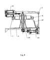
- Fig. 4 is a horizontal section of the drum which is simplified for best showing the internal mechanisms. There are shown sides 1, 2, spacer posts 3, drum 4, shaft 5, disc 6, gate 7, electromagnet 13 controlling the stepwise movement through pawl 17, and rod 16 lifting sequencer pawl 18. Conical segment 22 retaining the coins on the periphery of the drum is also shown.
- Fig. 5 shows coin input slot is, retaining conical segment 22, and output slot 1b for returning the coins.
- An electromagnet 23 controls through a plate 24 gate 7 which is returned by spring 8.
- Fig. 6 is a horizontal section along different planes which better illustrates as described above.
- Fig. 7 shows a coin (e) which is being introduced into the receiving drum 4, a coin (r) which is being returned, and a coin (i) which is being cashed after the operation of gate 7. It should be appreciated that the return position (r) and cash position (i) can be exchanged, if necessary, depending upon the length covered by the coins within the apparatus.
- Fig. 7b is a front view of the drum with the receiving pockets;
- Fig. 7a is a rear view showing the feed and control toothings.
- a coin put in a pay phone through the inlet slot is recognized and sorted by a coin selector (not shown) which then operates a gate for conveying said coin to feed duct 9.
- Photoelectric detector 11 at the input slot is connected to the receiving drum 4 is responsive to the control unit for operating the drum.
- the control unit energizes feed controlling electromagnet 13 by an electric pulse of predetermined length.
- Lever 15 operated by electromagnet core 13b rotates anticlockwise according to the view of Fig. 3 so that rod 16 slides leftwards.
- spring 20 is extended so as to accumulate energy, and ratchet pawl 17 is driven by rod 16 so as to pass over a tooth of gear 6c.
- Pawl 18 is rotated clockwise by rod 16 and slides on roll 18c of arm 18b with its upper edge 18e disengaging the latter from gear 6a.
- the rotation of disc 6 without control is prevented by ratchet pawl 19.
- the electromagnet is deenergized and spring 20 rotates lever 15 clockwise.
- the latter drives rod 16 together with pawl 17 rightwards so that such pawl engages gear 6c integral with receiving drum 4.
- drum 4 is caused to rotate clockwise besides by the above described ratchet gear operated by electromagnet 13 also by the weight of the coins in the pockets of drum 4.
- the pulsing electric power for energizing the electromagnet and for extending spring 20 is added to the potential energy due to the weight of the coins contained in the pockets for causing the collecting drum to rotate.
- the electric power necessary for operating the drum magazine is very low and can be directly derived from the telephone line without the need of expensive buffer batteries.
- Coins coming out of drum 4 can follow two ways: one way leading to a not shown return duct through slot 1b of front side 1, the second way leading to duct 25 the outlet of which is under the drum.
- the inlet port of said duct can be opened or closed by gate 7.
- photoelectric detector 26 senses the coin and sends a corresponding signal to the logic control unit. It should be appreciated that the electric power for operating the gate is very small and is consumed only for collection operations. For returning coins only the weight of the same is used. Photoelectric detectors 11 and 26 are of the double-control type to allow coins of different size to be detected. In particular, the detectors used in the embodiment of the invention are formed, as illustrated in Fig.
- optical guide 12 is formed by a semiannular molded piece of transparent plastic material having a high refractive index which allows the light to be guided within the thickness of said optical guide protected by a lining 12a due to the total reflection on the internal faces of the guide.
- control unit receives from a recognizing device an input information relative to the value of the coins inserted into the apparatus as well as from microswitches 21a, 21b an information about the angular position of the pocket of the rotating drum receiving the coin.
- Control unit has also an information stored in its memory about the amount to be paid for the supplied goods or service, said information being received, for example, from the exchange in case of a pay phone, and compares the value of the coins with said amount and collects or returns the coins under appropriate control signals fed to the electromagnet for opening the gate.
- drum rotation mechanism allows both the stepwise rotation to be manually actuated by pushing rod 16 against spring 20 and by next releasing the same, and the drum to be continuously rotated due to the disengagement of pawl 18.
Landscapes
- Engineering & Computer Science (AREA)
- Physics & Mathematics (AREA)
- General Physics & Mathematics (AREA)
- Computer Networks & Wireless Communication (AREA)
- Computer Security & Cryptography (AREA)
- Signal Processing (AREA)
- Control Of Vending Devices And Auxiliary Devices For Vending Devices (AREA)
- Vending Machines For Individual Products (AREA)
- Coin-Freed Apparatuses For Hiring Articles (AREA)
Applications Claiming Priority (2)
| Application Number | Priority Date | Filing Date | Title |
|---|---|---|---|
| ITRM910587 | 1991-08-01 | ||
| ITRM910587A IT1249825B (it) | 1991-08-01 | 1991-08-01 | Caricatore a tamburo rotante con asse orizzontale per un'unita' di accumulo e di gestione di monete o gettoni di un apparecchio per fornitura automatica di beni o servizi a prepagamento |
Publications (3)
| Publication Number | Publication Date |
|---|---|
| EP0526421A2 EP0526421A2 (en) | 1993-02-03 |
| EP0526421A3 EP0526421A3 (en) | 1993-04-21 |
| EP0526421B1 true EP0526421B1 (en) | 1997-04-02 |
Family
ID=11400306
Family Applications (1)
| Application Number | Title | Priority Date | Filing Date |
|---|---|---|---|
| EP92830393A Expired - Lifetime EP0526421B1 (en) | 1991-08-01 | 1992-07-17 | Rotating drum magazine having horizontal axis for the coin or token collecting and managing unit of an automatic apparatus for dispensing prepaid goods or services |
Country Status (5)
| Country | Link |
|---|---|
| EP (1) | EP0526421B1 (it) |
| AT (1) | ATE151186T1 (it) |
| DE (1) | DE69218691T2 (it) |
| ES (1) | ES2102486T4 (it) |
| IT (1) | IT1249825B (it) |
Families Citing this family (1)
| Publication number | Priority date | Publication date | Assignee | Title |
|---|---|---|---|---|
| GB0127731D0 (en) | 2001-11-20 | 2002-01-09 | Coin Controls | Coin handling apparatus |
Family Cites Families (6)
| Publication number | Priority date | Publication date | Assignee | Title |
|---|---|---|---|---|
| GB1245401A (en) * | 1967-06-12 | 1971-09-08 | Carreras Ltd | Change giving mechanism |
| GB2022897B (en) * | 1978-06-09 | 1982-07-07 | Post Office | Coin or token mechanisms |
| GB2070307A (en) * | 1980-02-18 | 1981-09-03 | Gen Electric Co Ltd | Coin handling |
| GB2097165A (en) * | 1981-04-10 | 1982-10-27 | Gen Electric Plc | Coin handling mechanism |
| ATE40759T1 (de) * | 1983-11-18 | 1989-02-15 | Autelca Ag | Muenzsammelbehaelter fuer selbstkassierer und muenzwechsler. |
| DE3541869A1 (de) * | 1985-11-27 | 1987-06-04 | Standard Elektrik Lorenz Ag | Speicher- und kassierverfahren und einrichtung zur durchfuehrung des verfahrens |
-
1991
- 1991-08-01 IT ITRM910587A patent/IT1249825B/it active IP Right Grant
-
1992
- 1992-07-17 AT AT92830393T patent/ATE151186T1/de active
- 1992-07-17 DE DE69218691T patent/DE69218691T2/de not_active Expired - Fee Related
- 1992-07-17 ES ES92830393T patent/ES2102486T4/es not_active Expired - Lifetime
- 1992-07-17 EP EP92830393A patent/EP0526421B1/en not_active Expired - Lifetime
Also Published As
| Publication number | Publication date |
|---|---|
| DE69218691D1 (de) | 1997-05-07 |
| EP0526421A2 (en) | 1993-02-03 |
| EP0526421A3 (en) | 1993-04-21 |
| IT1249825B (it) | 1995-03-28 |
| ITRM910587A0 (it) | 1991-08-01 |
| ES2102486T4 (es) | 1997-10-16 |
| ITRM910587A1 (it) | 1993-02-01 |
| ATE151186T1 (de) | 1997-04-15 |
| DE69218691T2 (de) | 1998-01-15 |
| ES2102486T3 (es) | 1997-08-01 |
Similar Documents
| Publication | Publication Date | Title |
|---|---|---|
| CA2134397C (en) | Coin dispenser | |
| USRE37662E1 (en) | Coin receiving and dispensing apparatus | |
| US4556139A (en) | Bill accepting device | |
| US5421443A (en) | Bill processing unit | |
| US4540081A (en) | Bill accepting device and method for controlling accepting of bills | |
| US5415264A (en) | Automatic vending machine for newspapers | |
| EP0643374B1 (en) | Electronic franking system comprising a mail handling mechanism | |
| US20080007146A1 (en) | Cash dispenser | |
| US5535894A (en) | Apparatus for conveying, accommodating and paying out bank notes | |
| US5381880A (en) | Electronic coin mechanism | |
| EP0560832B1 (en) | Coin validators | |
| EP0249598B1 (en) | Rotating drum magazine for storing and managing coins in telephone sets or dispensers | |
| EP0526421A2 (en) | Rotating drum magazine having horizontal axis for the coin or token collecting and managing unit of an automatic apparatus for dispensing prepaid goods or services | |
| US2728434A (en) | Coin mechanism and change maker embodying said mechanism | |
| JP3080774B2 (ja) | 硬貨処理装置 | |
| US3620340A (en) | Money-handling device | |
| CA2195910A1 (en) | Means for producing enhanced coin payout capacity in vending machines | |
| JPS6252914B2 (it) | ||
| GB2046975A (en) | Cash dispensing apparatus | |
| JP3765850B2 (ja) | 紙幣処理装置 | |
| JP2593335B2 (ja) | 自動カード発行機 | |
| CN218918168U (zh) | 一种硬币处理装置及现金循环处理设备 | |
| EP0496588A1 (en) | Coin mechanisms | |
| WO2005109355A2 (en) | Vending machine for articles | |
| JP2007236577A (ja) | 遊技メダルの一括投入システム |
Legal Events
| Date | Code | Title | Description |
|---|---|---|---|
| PUAI | Public reference made under article 153(3) epc to a published international application that has entered the european phase |
Free format text: ORIGINAL CODE: 0009012 |
|
| AK | Designated contracting states |
Kind code of ref document: A2 Designated state(s): AT BE CH DE DK ES FR GB GR LI LU MC NL PT SE |
|
| PUAL | Search report despatched |
Free format text: ORIGINAL CODE: 0009013 |
|
| AK | Designated contracting states |
Kind code of ref document: A3 Designated state(s): AT BE CH DE DK ES FR GB GR LI LU MC NL PT SE |
|
| 17P | Request for examination filed |
Effective date: 19930809 |
|
| 17Q | First examination report despatched |
Effective date: 19950301 |
|
| GRAG | Despatch of communication of intention to grant |
Free format text: ORIGINAL CODE: EPIDOS AGRA |
|
| GRAH | Despatch of communication of intention to grant a patent |
Free format text: ORIGINAL CODE: EPIDOS IGRA |
|
| GRAH | Despatch of communication of intention to grant a patent |
Free format text: ORIGINAL CODE: EPIDOS IGRA |
|
| GRAA | (expected) grant |
Free format text: ORIGINAL CODE: 0009210 |
|
| AK | Designated contracting states |
Kind code of ref document: B1 Designated state(s): AT BE CH DE DK ES FR GB GR LI LU MC NL PT SE |
|
| PG25 | Lapsed in a contracting state [announced via postgrant information from national office to epo] |
Ref country code: NL Effective date: 19970402 Ref country code: GR Free format text: LAPSE BECAUSE OF FAILURE TO SUBMIT A TRANSLATION OF THE DESCRIPTION OR TO PAY THE FEE WITHIN THE PRESCRIBED TIME-LIMIT Effective date: 19970402 Ref country code: DK Effective date: 19970402 Ref country code: BE Effective date: 19970402 Ref country code: AT Effective date: 19970402 |
|
| REF | Corresponds to: |
Ref document number: 151186 Country of ref document: AT Date of ref document: 19970415 Kind code of ref document: T |
|
| REG | Reference to a national code |
Ref country code: CH Ref legal event code: EP |
|
| REF | Corresponds to: |
Ref document number: 69218691 Country of ref document: DE Date of ref document: 19970507 |
|
| PG25 | Lapsed in a contracting state [announced via postgrant information from national office to epo] |
Ref country code: SE Effective date: 19970702 Ref country code: PT Effective date: 19970702 |
|
| REG | Reference to a national code |
Ref country code: CH Ref legal event code: NV Representative=s name: FIAMMENGHI-FIAMMENGHI |
|
| PG25 | Lapsed in a contracting state [announced via postgrant information from national office to epo] |
Ref country code: LU Free format text: LAPSE BECAUSE OF NON-PAYMENT OF DUE FEES Effective date: 19970717 |
|
| ET | Fr: translation filed | ||
| REG | Reference to a national code |
Ref country code: ES Ref legal event code: FG2A Ref document number: 2102486 Country of ref document: ES Kind code of ref document: T3 |
|
| NLV1 | Nl: lapsed or annulled due to failure to fulfill the requirements of art. 29p and 29m of the patents act | ||
| ET1 | Fr: translation filed ** revision of the translation of the patent or the claims | ||
| PG25 | Lapsed in a contracting state [announced via postgrant information from national office to epo] |
Ref country code: MC Free format text: LAPSE BECAUSE OF NON-PAYMENT OF DUE FEES Effective date: 19980131 |
|
| PLBE | No opposition filed within time limit |
Free format text: ORIGINAL CODE: 0009261 |
|
| 26N | No opposition filed | ||
| PGFP | Annual fee paid to national office [announced via postgrant information from national office to epo] |
Ref country code: ES Payment date: 20010709 Year of fee payment: 10 |
|
| PGFP | Annual fee paid to national office [announced via postgrant information from national office to epo] |
Ref country code: CH Payment date: 20010712 Year of fee payment: 10 |
|
| PGFP | Annual fee paid to national office [announced via postgrant information from national office to epo] |
Ref country code: DE Payment date: 20010717 Year of fee payment: 10 |
|
| PGFP | Annual fee paid to national office [announced via postgrant information from national office to epo] |
Ref country code: GB Payment date: 20010718 Year of fee payment: 10 |
|
| PGFP | Annual fee paid to national office [announced via postgrant information from national office to epo] |
Ref country code: FR Payment date: 20010731 Year of fee payment: 10 |
|
| REG | Reference to a national code |
Ref country code: GB Ref legal event code: IF02 |
|
| PG25 | Lapsed in a contracting state [announced via postgrant information from national office to epo] |
Ref country code: GB Free format text: LAPSE BECAUSE OF NON-PAYMENT OF DUE FEES Effective date: 20020717 |
|
| PG25 | Lapsed in a contracting state [announced via postgrant information from national office to epo] |
Ref country code: ES Free format text: LAPSE BECAUSE OF NON-PAYMENT OF DUE FEES Effective date: 20020718 |
|
| PG25 | Lapsed in a contracting state [announced via postgrant information from national office to epo] |
Ref country code: LI Free format text: LAPSE BECAUSE OF NON-PAYMENT OF DUE FEES Effective date: 20020731 Ref country code: CH Free format text: LAPSE BECAUSE OF NON-PAYMENT OF DUE FEES Effective date: 20020731 |
|
| PG25 | Lapsed in a contracting state [announced via postgrant information from national office to epo] |
Ref country code: DE Free format text: LAPSE BECAUSE OF NON-PAYMENT OF DUE FEES Effective date: 20030201 |
|
| GBPC | Gb: european patent ceased through non-payment of renewal fee |
Effective date: 20020717 |
|
| REG | Reference to a national code |
Ref country code: CH Ref legal event code: PL |
|
| PG25 | Lapsed in a contracting state [announced via postgrant information from national office to epo] |
Ref country code: FR Free format text: LAPSE BECAUSE OF NON-PAYMENT OF DUE FEES Effective date: 20030331 |
|
| REG | Reference to a national code |
Ref country code: FR Ref legal event code: ST |
|
| REG | Reference to a national code |
Ref country code: ES Ref legal event code: FD2A Effective date: 20030811 |