EP0526774A2 - Moteur électrique comportant un rotor sphérique et son appareil d'application - Google Patents
Moteur électrique comportant un rotor sphérique et son appareil d'application Download PDFInfo
- Publication number
- EP0526774A2 EP0526774A2 EP92111921A EP92111921A EP0526774A2 EP 0526774 A2 EP0526774 A2 EP 0526774A2 EP 92111921 A EP92111921 A EP 92111921A EP 92111921 A EP92111921 A EP 92111921A EP 0526774 A2 EP0526774 A2 EP 0526774A2
- Authority
- EP
- European Patent Office
- Prior art keywords
- rotor
- stator
- spherical
- magnets
- electric motor
- Prior art date
- Legal status (The legal status is an assumption and is not a legal conclusion. Google has not performed a legal analysis and makes no representation as to the accuracy of the status listed.)
- Granted
Links
- 239000003381 stabilizer Substances 0.000 claims abstract description 12
- 230000002706 hydrostatic effect Effects 0.000 claims description 17
- 239000000463 material Substances 0.000 claims description 7
- 239000012530 fluid Substances 0.000 claims description 2
- 206010034719 Personality change Diseases 0.000 claims 1
- 239000002245 particle Substances 0.000 claims 1
- 239000007787 solid Substances 0.000 claims 1
- 238000010276 construction Methods 0.000 description 13
- 230000007246 mechanism Effects 0.000 description 7
- 230000004308 accommodation Effects 0.000 description 5
- 239000013307 optical fiber Substances 0.000 description 5
- 238000010586 diagram Methods 0.000 description 4
- 230000000694 effects Effects 0.000 description 4
- 238000005096 rolling process Methods 0.000 description 3
- 230000000087 stabilizing effect Effects 0.000 description 3
- 239000011248 coating agent Substances 0.000 description 2
- 238000000576 coating method Methods 0.000 description 2
- 239000002826 coolant Substances 0.000 description 2
- 238000009501 film coating Methods 0.000 description 2
- 230000005389 magnetism Effects 0.000 description 2
- 239000011347 resin Substances 0.000 description 2
- 229920005989 resin Polymers 0.000 description 2
- 239000010409 thin film Substances 0.000 description 2
- 230000000007 visual effect Effects 0.000 description 2
- 238000004804 winding Methods 0.000 description 2
- 238000013019 agitation Methods 0.000 description 1
- 230000008859 change Effects 0.000 description 1
- 239000000470 constituent Substances 0.000 description 1
- 238000001816 cooling Methods 0.000 description 1
- 230000008878 coupling Effects 0.000 description 1
- 238000010168 coupling process Methods 0.000 description 1
- 238000005859 coupling reaction Methods 0.000 description 1
- 238000001514 detection method Methods 0.000 description 1
- 238000007667 floating Methods 0.000 description 1
- 230000001939 inductive effect Effects 0.000 description 1
- 239000000696 magnetic material Substances 0.000 description 1
- 238000012423 maintenance Methods 0.000 description 1
- 230000003287 optical effect Effects 0.000 description 1
- 230000000149 penetrating effect Effects 0.000 description 1
- 230000009467 reduction Effects 0.000 description 1
- 239000004576 sand Substances 0.000 description 1
- 238000009987 spinning Methods 0.000 description 1
Images



Classifications
-
- H—ELECTRICITY
- H02—GENERATION; CONVERSION OR DISTRIBUTION OF ELECTRIC POWER
- H02K—DYNAMO-ELECTRIC MACHINES
- H02K41/00—Propulsion systems in which a rigid body is moved along a path due to dynamo-electric interaction between the body and a magnetic field travelling along the path
- H02K41/02—Linear motors; Sectional motors
- H02K41/03—Synchronous motors; Motors moving step by step; Reluctance motors
- H02K41/031—Synchronous motors; Motors moving step by step; Reluctance motors of the permanent magnet type
-
- B—PERFORMING OPERATIONS; TRANSPORTING
- B01—PHYSICAL OR CHEMICAL PROCESSES OR APPARATUS IN GENERAL
- B01F—MIXING, e.g. DISSOLVING, EMULSIFYING OR DISPERSING
- B01F35/00—Accessories for mixers; Auxiliary operations or auxiliary devices; Parts or details of general application
- B01F35/30—Driving arrangements; Transmissions; Couplings; Brakes
- B01F35/32—Driving arrangements
-
- G—PHYSICS
- G01—MEASURING; TESTING
- G01C—MEASURING DISTANCES, LEVELS OR BEARINGS; SURVEYING; NAVIGATION; GYROSCOPIC INSTRUMENTS; PHOTOGRAMMETRY OR VIDEOGRAMMETRY
- G01C19/00—Gyroscopes; Turn-sensitive devices using vibrating masses; Turn-sensitive devices without moving masses; Measuring angular rate using gyroscopic effects
- G01C19/02—Rotary gyroscopes
- G01C19/04—Details
-
- G—PHYSICS
- G01—MEASURING; TESTING
- G01C—MEASURING DISTANCES, LEVELS OR BEARINGS; SURVEYING; NAVIGATION; GYROSCOPIC INSTRUMENTS; PHOTOGRAMMETRY OR VIDEOGRAMMETRY
- G01C21/00—Navigation; Navigational instruments not provided for in groups G01C1/00 - G01C19/00
- G01C21/10—Navigation; Navigational instruments not provided for in groups G01C1/00 - G01C19/00 by using measurements of speed or acceleration
- G01C21/12—Navigation; Navigational instruments not provided for in groups G01C1/00 - G01C19/00 by using measurements of speed or acceleration executed aboard the object being navigated; Dead reckoning
- G01C21/16—Navigation; Navigational instruments not provided for in groups G01C1/00 - G01C19/00 by using measurements of speed or acceleration executed aboard the object being navigated; Dead reckoning by integrating acceleration or speed, i.e. inertial navigation
-
- H—ELECTRICITY
- H02—GENERATION; CONVERSION OR DISTRIBUTION OF ELECTRIC POWER
- H02K—DYNAMO-ELECTRIC MACHINES
- H02K7/00—Arrangements for handling mechanical energy structurally associated with dynamo-electric machines, e.g. structural association with mechanical driving motors or auxiliary dynamo-electric machines
- H02K7/08—Structural association with bearings
- H02K7/085—Structural association with bearings radially supporting the rotary shaft at only one end of the rotor
-
- H—ELECTRICITY
- H02—GENERATION; CONVERSION OR DISTRIBUTION OF ELECTRIC POWER
- H02K—DYNAMO-ELECTRIC MACHINES
- H02K7/00—Arrangements for handling mechanical energy structurally associated with dynamo-electric machines, e.g. structural association with mechanical driving motors or auxiliary dynamo-electric machines
- H02K7/14—Structural association with mechanical loads, e.g. with hand-held machine tools or fans
-
- G—PHYSICS
- G01—MEASURING; TESTING
- G01C—MEASURING DISTANCES, LEVELS OR BEARINGS; SURVEYING; NAVIGATION; GYROSCOPIC INSTRUMENTS; PHOTOGRAMMETRY OR VIDEOGRAMMETRY
- G01C19/00—Gyroscopes; Turn-sensitive devices using vibrating masses; Turn-sensitive devices without moving masses; Measuring angular rate using gyroscopic effects
- G01C19/02—Rotary gyroscopes
- G01C19/04—Details
- G01C19/16—Suspensions; Bearings
- G01C19/18—Suspensions; Bearings providing movement of rotor with respect to its rotational axes
-
- G—PHYSICS
- G01—MEASURING; TESTING
- G01C—MEASURING DISTANCES, LEVELS OR BEARINGS; SURVEYING; NAVIGATION; GYROSCOPIC INSTRUMENTS; PHOTOGRAMMETRY OR VIDEOGRAMMETRY
- G01C19/00—Gyroscopes; Turn-sensitive devices using vibrating masses; Turn-sensitive devices without moving masses; Measuring angular rate using gyroscopic effects
- G01C19/02—Rotary gyroscopes
- G01C19/04—Details
- G01C19/16—Suspensions; Bearings
- G01C19/24—Suspensions; Bearings using magnetic or electrostatic fields
-
- G—PHYSICS
- G01—MEASURING; TESTING
- G01C—MEASURING DISTANCES, LEVELS OR BEARINGS; SURVEYING; NAVIGATION; GYROSCOPIC INSTRUMENTS; PHOTOGRAMMETRY OR VIDEOGRAMMETRY
- G01C19/00—Gyroscopes; Turn-sensitive devices using vibrating masses; Turn-sensitive devices without moving masses; Measuring angular rate using gyroscopic effects
- G01C19/58—Turn-sensitive devices without moving masses
- G01C19/64—Gyrometers using the Sagnac effect, i.e. rotation-induced shifts between counter-rotating electromagnetic beams
- G01C19/72—Gyrometers using the Sagnac effect, i.e. rotation-induced shifts between counter-rotating electromagnetic beams with counter-rotating light beams in a passive ring, e.g. fibre laser gyrometers
-
- H—ELECTRICITY
- H02—GENERATION; CONVERSION OR DISTRIBUTION OF ELECTRIC POWER
- H02K—DYNAMO-ELECTRIC MACHINES
- H02K2201/00—Specific aspects not provided for in the other groups of this subclass relating to the magnetic circuits
- H02K2201/18—Machines moving with multiple degrees of freedom
-
- Y—GENERAL TAGGING OF NEW TECHNOLOGICAL DEVELOPMENTS; GENERAL TAGGING OF CROSS-SECTIONAL TECHNOLOGIES SPANNING OVER SEVERAL SECTIONS OF THE IPC; TECHNICAL SUBJECTS COVERED BY FORMER USPC CROSS-REFERENCE ART COLLECTIONS [XRACs] AND DIGESTS
- Y10—TECHNICAL SUBJECTS COVERED BY FORMER USPC
- Y10T—TECHNICAL SUBJECTS COVERED BY FORMER US CLASSIFICATION
- Y10T74/00—Machine element or mechanism
- Y10T74/12—Gyroscopes
- Y10T74/1218—Combined
-
- Y—GENERAL TAGGING OF NEW TECHNOLOGICAL DEVELOPMENTS; GENERAL TAGGING OF CROSS-SECTIONAL TECHNOLOGIES SPANNING OVER SEVERAL SECTIONS OF THE IPC; TECHNICAL SUBJECTS COVERED BY FORMER USPC CROSS-REFERENCE ART COLLECTIONS [XRACs] AND DIGESTS
- Y10—TECHNICAL SUBJECTS COVERED BY FORMER USPC
- Y10T—TECHNICAL SUBJECTS COVERED BY FORMER US CLASSIFICATION
- Y10T74/00—Machine element or mechanism
- Y10T74/12—Gyroscopes
- Y10T74/1229—Gyroscope control
- Y10T74/1232—Erecting
- Y10T74/125—Erecting by magnetic field
-
- Y—GENERAL TAGGING OF NEW TECHNOLOGICAL DEVELOPMENTS; GENERAL TAGGING OF CROSS-SECTIONAL TECHNOLOGIES SPANNING OVER SEVERAL SECTIONS OF THE IPC; TECHNICAL SUBJECTS COVERED BY FORMER USPC CROSS-REFERENCE ART COLLECTIONS [XRACs] AND DIGESTS
- Y10—TECHNICAL SUBJECTS COVERED BY FORMER USPC
- Y10T—TECHNICAL SUBJECTS COVERED BY FORMER US CLASSIFICATION
- Y10T74/00—Machine element or mechanism
- Y10T74/12—Gyroscopes
- Y10T74/1282—Gyroscopes with rotor drive
Definitions
- the present invention relates to an electric motor having a spherical rotor, which is available for driving an optical sensor, a control moment gyro, an inductive detector device or an electromagnetic wave transmitter of an aircraft, a flying object or the like, or a visual sensor of a robot, and its application apparatus.
- a "spherical surface motor” which is representative of multi-freedom electric motors disclosed in a Japanese patent application filed on March 22, 1986 (Laid-Open Japanese Patent Specification No. 62-221856 (1987)), has been known.
- This motor comprises, as shown in Fig. 16-(a), a hemispherical rotor 103 consisting of permanent magnets 101 or of permanent magnets 101 and yokes 102, a stator 105 having a plurality of windings 104 arrayed on a hemispherical surface and a spherical bearing 107 for rotatably supporting an output shaft 106 from the stator 105, and as shown in Fig.
- a driving torque of any arbitrary direction was generated by controlling a current flowing through the respective windings 104 of the above-mentioned stator 105 in a magnetic field produced by the permanent magnets 101 whose N-poles and S-poles are arranged along the surface of the above-mentioned hemispherical rotor 103.
- an electric motor having a spherical rotor, comprising a rotor formed in a spherical shape and having a plurality of magnets disposed contiguously on its outer surface so that the polarities of the respective adjacent magnetic poles may differ from one another, a stator provided along the outer surface of the same rotor and having a plurality of magnets disposed on its inner surface side as opposed to the magnets on the rotor, a spherical bearing coupled to the same stator for rotatably supporting the outer surface of the rotor, either the magnets of the rotor or the magnets of the stator being formed as electromagnets, and a controller connected to the respective electromagnets for controlling electric currents flowing through the respective electromagnets to rotate the rotor about a displaceable rotary axis.
- the above-featured electric motor having a spherical rotor, wherein the spherical rotor is formed in a spherical shell shape to reserve a wide accommodation space for a loaded article within the spherical shell.
- the electric motor having a spherical rotor operates in the following manner. That is, when an operating direction command signal for the rotor has been input to the controller, the controller calculates electromagnetic forces to be generated by the respective electromagnets in the stator or the rotor, thus determines magnitudes of the currents to be made to flow through the respective electromagnets, and feeds the currents. The electromagnetic forces generated by the electromagnets as a result of this feeding of currents, would act upon the permanent magnets provided on the surface of the rotor or the stator.
- the rotor Since the above-mentioned rotor is rotatably supported by the spherical bearing, it is driven when the electromagnetic forces act upon the above-mentioned permanent magnets, the rotor performs rotation in the predetermined direction based on the above-mentioned operating direction command signal.
- the rotor because of the fact that permanent magnets or electromagnets are disposed on the almost entire surface of the outer surface of the spherical rotor and the magnetic forces of the electromagnets or permanent magnets of the stator are adapted to act upon a part of the either magnets of the rotor, the rotor has a wide operation range, and also because of the fact that the rotor has a simple structure provided with either permanent magnets or electromagnets on its outer surface, it is possible to reserve a space within the rotor and to utilize the space.
- a multi-freedom electric motor in which a rotor has a wide operation range and a broad accommodation space for a loaded article is reserved within the rotor, can be realized.
- a space stabilizing apparatus in which a gyro is accommodated within a rotor, and on the basis of an output signal of the gyro, the same rotor is rotated to a predetermined position so that the gyro may be directed always in a predetermined direction.
- a control moment gyro comprising a flywheel consisting of a spherical rotor having a plurality of magnets with magnetic poles of different polarities disposed in a lattice-shaped array on its outer surface, and a gimbal consisting of a spherical stator disposed on the outside of this spherical rotor via a hydrostatic bearing and having a plurality of electromagnets disposed on its inner surface.
- an agitator in which agitating blades are provided on the inner surface of the above-mentioned hollow spherical rotor, and this spherical rotor is rotated by controlling the electromagnets of the above-mentioned stator.
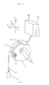
- FIG. 1 An electric motor having a spherical rotor according to a first preferred embodiment of the present invention is illustrated in Fig. 1.
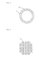
- reference numeral 1 designates a spherical rotor, which has a hollow spherical shape as shown in Fig. 2.
- On the outer surface of the spherical rotor 1 are mounted a plurality of permanent magnets 2 in a lattice form with polarities of adjacent magnetic poles differring from one another as shown in Fig. 3.
- the scope of mounting of the permanent magnets 2 excludes the polar portions of the spherical rotor 1, where arrangement with adjacent magnetic poles having different polarities from one another is impossible, as shown in Fig. 4.
- Reference numeral 3 designates a stator provided outside of the above-mentioned spherical rotor 1, on its inside surface opposed to the surface of the spherical rotor 1 are disposed electromagnets 4 in a lattice form and in a spherical array as shown in Fig. 5, and the interval between the electromagnets 4 of the above-mentioned stator 3 is chosen to be 2/3 of an average value of the intervals between the permanent magnets 2 of the spherical rotor 1.
- Reference numeral 5 designates a hydrostatic bearing (spherical bearing) coupled to the aforementioned stator 3 and surrounding one round of the outer circumference of the above-described spherical rotor 1, which is pressurized by a pressure of gas supplied from a pressurized gas bomb 6 via a pressurizing pipe 9.
- This hydrostatic bearing 5 makes use of the spherical surface of the spherical rotor 1 as a part of a spherical bearing, and the spherical rotor is held in a non-contact manner.
- Reference numeral 7 designates an angular velocity detector for detecting three coordinate components of an angular velocity, the angular velocity signals are sent to a controller 8 as will be described later via wirings not shown, and in this controller the position of the spherical rotor 1 is detected by integrating the angular velocity signals. In addition, on the basis of these position signals, a relative position of the spherical rotor 1 with respect to the stator 3 is calculated.
- Reference numeral 8 designates a controller, which is connected to the respective electromagnets 4 of the above-mentioned stator 3 and the angular velocity detector via wirings.
- the controller 8 operates as illustrated by the functional block diagram in Fig. 6, and controls the electromagnets 4 of the stator 3. More particularly, at first an operational direction command signal (or a force direction command signal) of the spherical rotor 1 and angular velocity signals of the spherical rotor 1 are input to the controller 8. The controller 8 having these signals input integrates the latter input signals to convert them into position signals, and calculates a relative position of the spherical rotor 1 with respect to the stator 3 by making use of these position signals.
- an operational direction command signal or a force direction command signal
- Electromagnetic forces to be generated by the respective electromagnets 4 are calculated according to these relative position signals and the operational direction command signal (or the force direction command signal) on the basis of a logic sequence corresponding to a magnetic field condition, thus values of currents to be fed to the respective electromagnets 4 are calculated, and the currents are supplied.
- the coupling between the above-mentioned stator 3 and spherical rotor 1 relies upon the hydrostatic bearing 5 which keeps the spherical rotor 1 in a floating condition by means of the pressure of the gas supplied from the pressurized gas bomb 6, the spherical rotor 1 is freely rotatable in any direction. Therefore, if electromagnetic forces are generated at the respective electromagnets 4 of the stator 3, they act upon the magnetism of the permanent magnets 2 of the spherical rotor 1 to cause the spherical rotor 1 to perform predetermined actions.
- the reason why the interval between the electromagnets 4 of the stator 3 is chosen to be 2/3 times an average value of the intervals between the permanent magnets 2 of the spherical rotor 1, is because of the purpose of generating driving forces at the spherical rotor 1.
- the permanent magnets 2 which do not necessitate wirings, an especially broad space can be reserved within the rotor, and also since its movement is not restricted by wirings, rotational movement over a very broad range becomes possible.
- FIG. 7 A second preferred embodiment of the present invention is illustrated in Fig. 7.
- a spherical bearing 14 is disposed at a symmetrical position to a stator 3 with a spherical rotor 1 placed therebetween, also a camera 10 (a picture camera, an infrared ray camera, etc.) is contained in the spherical rotor 1 by making use of a mounting space within the spherical rotor 1, and the electric motor having the spherical rotor is utilized as an orientation control apparatus for the camera 10.
- a camera 10 a picture camera, an infrared ray camera, etc.
- the camera 10 is fixed to the hollow section inside of the spherical rotor 1, the spherical rotor 1 supported by the stator 3 and the spherical bearing 14 is caused to swing by controlling the currents fed to the respective electromagnets 4 on the stator 3, according to this swing motion the orientation of the camera 10 is arbitrarily varied, and photographing is effected through a lens 11.
- the rotor position signals used for phase detection between the spherical rotor 1 and the stator 3 can be used also for the purpose of feedback for the purpose of position control.
- FIG. 8 A third preferred embodiment of the present invention is illustrated in Fig. 8.
- This preferred embodiment shown in Fig. 8 is the case of an electric motor having a spherical rotor, wherein in place of the hydrostatic bearing 5 of the first preferred embodiment, a magnetic bearing formed by the electromagnets 4 of the stators 3 is used.
- the stators 3 are opposed at the positions symmetric to each other with respect to the center of the spherical rotor 1. Since the magnetic forces generated between the electromagnets 4 of the stators 3 and the permanent magnets 2 in the spherical rotor 1 are decomposed into forced directed towards the center of the spherical rotor 1 and forces (torques) directed in the tangential direction of the spherical rotor 1, by controlling not only the latter forces but also the former forces with respect to the two opposed stators 3, it is possible to cause the stators 3 to have a function of a magnetic bearing.
- the torque can be also doubled.
- FIG. 9 A fourth preferred embodiment of the present invention is shown in Fig. 9.
- This preferred embodiment shown in Fig. 9 is the case of an electric motor having a spherical rotor, wherein in place of the hydrostatic bearing 5 of the first preferred embodiment, a sliding bearing is used.
- thin film coatings 12 and 13 of resin are applied over the respective surfaces of the spherical rotor 1 and the stator 3. Also, at a position symmetric to the stator 3 with respect to the center of the spherical rotor 1 is disposed a spherical bearing 14, and like the stator 3 this spherical bearing 14 is applied with a coating. In this preferred embodiment, adjustment of frictional forces can be achieved by holding a constant surface pressure as a result of positional adjustment of the stator 3 and the spherical bearing 14.
- FIG. 10 A fifth preferred embodiment of the present invention is illustrated in Fig. 10.
- This preferred embodiment shown in Fig. 10 is the case of an electric motor having a spherical rotor, wherein in place of the hydrostatic bearing 5 of the first preferred embodiment, a roller bearing is used.
- the spherical rotor 1 is held by inserting rolling bearings between the spherical rotor 1 and the stator 3 and between a spherical bearing 14 disposed at a position symmetric to the stator 3 with respect to the center of the spherical rotor 1 and the rotor 1.
- the electric motor having a spherical rotor according to the present invention can realize a multi-freedom electric motor, which is simple in structure and can be small-sized, and in which damage would hardly occur, an operation range of the rotor is wide, and moreover a broad accommodation space for a loaded article is reserved within the rotor.
- the use of the multi-freedom electric motor according to the present invention is broad, and as one example of the use, it can be used as a drive power source of an agitator as will be described in the following.
- Fig. 11 shows one example of a mixer making use of a 3-freedom motor.
- reference numeral 21 designates a multi-freedom motor provided at the bottom of the inside of a container 25 of inverse-cone shape
- numeral 23 designates an agitating screw having its bottom end connected to the above-mentioned multi-freedom motor 21 and its top end connected to a bearing 22a, to the above-mentioned bearing 22a is connected one end of an arm 24, and the other end thereof is connected to another bearing 22b provided at the top of the inside of the container 25.
- the multi-freedom motor 21 if electromagnetic forces are generated at respective electromagnets of a stator, then they act upon the magnetisms of permanent magnets of a spherical rotor, and the spherical rotor is driven in the direction instructed by an operational direction command signal and rotates.
- a ratio of a spinning speed to a revolving speed of the screw can be chosen arbitrarily, and by adjusting this ratio depending upon the material to be agitated, optimum mixing of the material to be agitated can be realized.
- the space stabilizer is an apparatus for stabilizing a guidance detector (a visual sensor of a robot, an infrared-ray camera or the like) or an electromagnetic wave transmitter so as to take a spatially stable attitude despite of movement of an airframe such as rocking or rotation of an airframe in an aircraft or a flying object.
- a guidance detector a visual sensor of a robot, an infrared-ray camera or the like
- an electromagnetic wave transmitter so as to take a spatially stable attitude despite of movement of an airframe such as rocking or rotation of an airframe in an aircraft or a flying object.
- an annular hydrostatic bearing 14 Within the same bearing 14 is disposed a spherical rotor 1 consisting of a spherical shell having a plurality of permanent magnets 2 so as to be able to freely perform multi-freedom rotation without friction with a predetermined clearance maintained therebetween owing to a hydrostatic pressure. Also, a stator 3 having a plurality of electromagnets is provided as opposed to the spherical rotor 1.
- the construction of the spherical rotor 1 is similar to that of the first preferred embodiment explained above with reference to Figs. 2 to 4, and the construction of the stator 3 is similar to that of the first preferred embodiment explained above with reference to Figs. 5 and 7.
- an infrared-ray camera 31 coaxially with the Z-axis penetrating through the rotor 1 so as to pass its center. Also, within the spherical rotor 1 are provided optical fiber gyros 32 for the X-axis, Y-axis and Z-axis, respectively.
- reference numeral 33 designates a gyro controller provided within the spherical rotor 1
- numeral 34 designates a video signal processor
- numeral 35 designates an accumulator.
- reference numeral 36 designates a hydrostatic bearing seal
- numeral 37 designates a coolant piping for cooling the infrared-ray camera
- numeral 38 designates a pressurized air bomb connected to the hydrostatic spherical bearing 14 and the coolant piping 37.
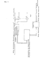
- FIG. 13 A functional block diagram for the above-mentioned apparatus is shown in Fig. 13.
- An output of the infrared-ray camera 31 is sent via the video signal processor 34 to an addition input of an adder 39.
- an output of the optical fiber gyro 32 is sent via the gyro controller 32 to a subtraction input of the adder 39.
- an output of the gyro controller 32 is sent to a control-calculator 42 via an integrator 40 and a rotor/stator relative position calculator 41, sequentially.
- An output of the adder 39 is sent to the control-calculator 42.
- an output of the control-calculator 42 is sent to the stator 3.
- the integrator 40, the rotor/stator relative position calculator 41 and the control-calculator 42 jointly form a controller 43.
- the spherical rotor floats up on the hydrostatic spherical bearing 14 as spaced at a predetermined interval so as to arbitrarily make multi-freedom rotation.
- a signal detected by the optical fiber gyro 32 is converted into a rotor angular velocity signal via the gyro controller 33, and the latter is sent to the adder 39 and the controller 43.
- This angular velocity signal is integrated in the integrator 40 and becomes a rotor position signal.
- This rotor position signal is calculated in the rotor/stator relative position calculator 41 and converted into a relative position, and then it is sent to the control calculator 42.
- an error signal of the guide signal minus the rotor angular velocity signal sent from the adder 39 is transmitted to the control calculator 42.
- the control calculator 42 transmits positional operation signals to the respective coils of the stator 3 so as to direct the infrared-ray camera 31 of the spherical rotor 1 to a predetermined direction on the basis of these signals.
- the respective coils are energized by the input signals, thereby rotate the spherical rotor 1 as a multi-freedom motor, and maintain the orientation of the infrared-ray camera 31 in the predetermined direction within the flying object 30.
- the spherical rotor 1 can perform multi-freedom rotation, the operation range is broad, and a high precision can be obtained. Moreover, in addition to the fact that as compared to the apparatuses in the prior art, in these instruments, complicated gimbal mechanisms nor a plurality of motors and controllers have become unnecessary, as a result of the fact that optical fiber gyros and other component parts are contained within the rotor and the spherical rotor and the spherical rotor are integrated, the apparatus becomes very simple and cheap. In addition, since the spherical rotor is coupled via a spherical bearing, in principle there is no limitation to an operation range. Furthermore, as an outer diameter of the rotor can be made large as compared to a general motor, a large generation torque can be obtained, and a space stabilizing capability is improved.
- an infrared-ray camera 31 as a detector has been disclosed in the above description, it is a matter of course that if this infrared-ray camera 31 is replaced by a passive electromagnetic wave radar, a passive sonar or the like, then an electromagnetic wave detector or a sound wave detector having similar effects and advantages to this preferred embodiment can be provided. It is also self-explanatory that likewise if the above-mentioned detector is replaced respectively for delivery ports of an active electromagnetic wave radar, a laser transmitter, a CCD, an active sonar, a fire extinguisher and a sand blast, then an emitter having similar effects and advantages to this preferred embodiment can be provided. As described above, by loading a detector or a transmitter of an electromagnetic wave, light, a sound wave or the like on the illustrated space stabilizer, a detector having a broad operation range, a good space stability and a larger output for the same space, can be provided.
- a magnetic bearing making use of electromagnets a spherical bearing in which a surface pressure is kept constant by inserting a thin film coating of resin between a rotor and a stator, or a spherical coating in which a rolling bearing is disposed between a rotor and a stator, could be employed.
- a hydrostatic bearing in which fluid is blown onto a rotor should be used.
- the apparatus since an optical fiber gyro is used as the gyro, the apparatus has a merit that it is light in weight and has a small inertia, and also because of a small number of movable mechanical parts it has a long life and it is maintenance free.
- the gyro various kinds of gyros could be used depending upon the purposes.
- the illustrated apparatus is provided with a spherical rotor having a plurality of permanent magnets, a spherical bearing for supporting the rotor so as to arbitrarily perform multi-freedom rotation, there is provided a space stabilizer, in which a mechanism becomes very simple, an operation range is broad, and a high precision as well as a high stability are realized.
- CMG control moment gyro
- a flywheel 52 rotating at a high speed about a ⁇ -axis as driven by a spin motor 51 connected to a controller 54 is supported by means of a gimbal 53, this gimbal 53 is rotated about a e-axis by means of a gimbal driving motor 55 connected to the controller 54, thus a torque about a q)-axis is obtained as a result of a gyro effect, and by arranging a plurality of such apparatuses, attitude control in an arbitrary space was carried out.
- reference numeral 1 designates a spherical rotor which also serves as a flywheel.
- This spherical rotor 1 basically has a similar construction to that described previously with reference to Figs. 2 and 3.
- Reference numeral 3 designates a stator provided outside of the spherical rotor 1, and this also serves as a gimbal. The construction of this stator 3 is basically similar to the construction in the first preferred embodiment described above with reference to Figs. 4 and 5.
- a combined position detector and angular velocity detector 60 for detecting a position (o and 0 positions) of the spherical rotor 1.
- Reference numeral 61 designates a rotary guide for limiting the direction of rotation of the spherical rotor 1 to about the ⁇ -axis and about the e-axis, and this is fixed to the combined spherical stator and gimbal 3.
- Reference numeral 62 designates a controller which controls the electric currents supplied to the electromagnets 4 on the basis of external or internal command signals and a feedback signal sent from the combined position detector and angular velocity detector 60 so that the spherical rotor 1 may take predetermined position and velocity.
- a hydrostatic bearing to permit arbitrary rotation of the spherical rotor 1.
- the above-described electromagnetic forces generated by the respective electromagnets 4 act upon magnetic pole elements 2 of the spherical rotor 1 and cause the spherical rotor 1 serving as a flywheel to rotate at a constant velocity about the ⁇ -axis, thereby an angular momentum H about the ⁇ -axis is generated, and also they cause the spherical rotor 1 to rotate at a given velocity about the e-axis to generate an angular velocity vector about the e-axis.
- This preferred embodiment is a three-dimensional agitator making use of the principle of the multi-freedom electric motor according to the present invention.
- reference numeral 1 designates a hollow spherical rotor similar to the rotor of the multi-freedom motor in the first preferred embodiment, and onto the inner surface of this spherical rotor 1 are mounted blades or scrapers according to the purpose.
- blades 71 are mounted onto the spherical inner surface of the spherical rotor 1.
- Reference numeral 3 designates a stator disposed outside of the above-mentioned spherical rotor 1 and having a plurality of electromagnets not shown disposed on its inner surface side, and the same electromagnets are connected to a controller not shown.
- Reference numeral 14 designates a spherical hydrostatic bearing provided on the inner surface of the above-mentioned stator 3, and this hydrostatic bearing 4 is pressurized by a gas pressure applied from a pressurized gas bomb 6 to hold the spherical rotor 1 in a non-contact manner.
- Reference numeral 72 designates an intake/exhaust port, and numeral 73 designates a seal member.
- the spherical rotor 1 is freely rotatable in any direction similarly to the case of the first preferred embodiment, by charging material to be agitated into the spherical rotor 1 through the intake/exhaust port 72 and rotating the spherical rotor 1 in the three-dimensional direction on the basis of an operation direction command signal sent from the controller, agitation of the material to be agitated can be done without causing unevenness, and an object can be achieved.
- This preferred embodiment is characteristic in that an output shaft is unnecessary, and that a large output can be obtained because of a large rotor radius, and it can be adapted to material having a high viscosity.
Landscapes
- Engineering & Computer Science (AREA)
- Power Engineering (AREA)
- Physics & Mathematics (AREA)
- Radar, Positioning & Navigation (AREA)
- Remote Sensing (AREA)
- Chemical & Material Sciences (AREA)
- Combustion & Propulsion (AREA)
- Electromagnetism (AREA)
- General Physics & Mathematics (AREA)
- Chemical Kinetics & Catalysis (AREA)
- Automation & Control Theory (AREA)
- Magnetic Bearings And Hydrostatic Bearings (AREA)
- Connection Of Motors, Electrical Generators, Mechanical Devices, And The Like (AREA)
Applications Claiming Priority (8)
| Application Number | Priority Date | Filing Date | Title |
|---|---|---|---|
| JP6042291U JP2542763Y2 (ja) | 1991-07-31 | 1991-07-31 | 多自由度モータを用いた粉体機器 |
| JP60422/91U | 1991-07-31 | ||
| JP218567/91 | 1991-08-29 | ||
| JP21856791A JP2766745B2 (ja) | 1991-08-29 | 1991-08-29 | コントロールモーメントジャイロ |
| JP220001/91 | 1991-08-30 | ||
| JP22000191A JPH0564417A (ja) | 1991-08-30 | 1991-08-30 | 球状ロータを有する電動機 |
| JP297251/91 | 1991-11-13 | ||
| JP29725191A JP2772180B2 (ja) | 1991-11-13 | 1991-11-13 | 空間安定化装置、検出装置及び発射装置 |
Publications (3)
| Publication Number | Publication Date |
|---|---|
| EP0526774A2 true EP0526774A2 (fr) | 1993-02-10 |
| EP0526774A3 EP0526774A3 (fr) | 1994-02-16 |
| EP0526774B1 EP0526774B1 (fr) | 1996-03-20 |
Family
ID=27463913
Family Applications (1)
| Application Number | Title | Priority Date | Filing Date |
|---|---|---|---|
| EP92111921A Expired - Lifetime EP0526774B1 (fr) | 1991-07-31 | 1992-07-13 | Moteur électrique comportant un rotor sphérique et son appareil d'application |
Country Status (3)
| Country | Link |
|---|---|
| US (3) | US5413010A (fr) |
| EP (1) | EP0526774B1 (fr) |
| DE (1) | DE69209187T2 (fr) |
Cited By (7)
| Publication number | Priority date | Publication date | Assignee | Title |
|---|---|---|---|---|
| DE19722814A1 (de) * | 1997-05-30 | 1998-12-03 | Dirk Dipl Ing Prust | Mehrachsiger Antrieb mit variabler Polung |
| WO1998046967A3 (fr) * | 1997-03-20 | 1999-01-21 | Honeywell Inc | Detecteur de vitesse relative pour des gyroscopes a inertie de regulation |
| EP1480318A1 (fr) * | 2003-05-20 | 2004-11-24 | Northrop Grumman Corporation | Moteur sphérique utilisant champs magnétiques oscillants |
| EP2075897A2 (fr) | 2007-12-29 | 2009-07-01 | The Robert Gordon University | Appareil électromécanique |
| FR2961306A1 (fr) * | 2010-06-14 | 2011-12-16 | Eurocopter France | Moteur electrique pour systeme de mesure inertielle et systeme de mesure inertielle comportant un tel moteur |
| US8555734B2 (en) | 2005-08-22 | 2013-10-15 | Technology Investment Company Pty Ltd | Stabilising means |
| CN109802513A (zh) * | 2019-01-31 | 2019-05-24 | 河北科技大学 | 永磁转子驱动式多自由度运动电机 |
Families Citing this family (83)
| Publication number | Priority date | Publication date | Assignee | Title |
|---|---|---|---|---|
| US5555059A (en) * | 1992-11-10 | 1996-09-10 | Samsung Aerospace Industries, Ltd. | Electromagnetic lens shutter apparatus |
| JPH09168275A (ja) * | 1995-12-15 | 1997-06-24 | Mitsubishi Heavy Ind Ltd | 多自由度電動機 |
| US5839386A (en) * | 1996-05-08 | 1998-11-24 | Edward Frieling | Vehicle stabilizing by rotating mass |
| US6145393A (en) * | 1998-11-27 | 2000-11-14 | Canton; Dino | Floated gimbal optical platform |
| US6326714B1 (en) * | 1999-10-27 | 2001-12-04 | Moog Inc. | Two-axis pointing motor |
| AU2002211680A1 (en) | 2000-10-13 | 2002-04-22 | Clarity, L.L.C. | Magnetic actuation and positioning |
| US20020118594A1 (en) * | 2001-02-28 | 2002-08-29 | Vellinger John C. | Apparatus and method for mixing small volumes of liquid |
| RU2193159C1 (ru) * | 2001-10-16 | 2002-11-20 | Федеральное государственное унитарное предприятие Центральный научно-исследовательский институт "Электроприбор" | Гирокамера электростатического гироскопа |
| US6879082B2 (en) * | 2002-03-25 | 2005-04-12 | Clarity Technologies, Inc. | Electromagnetic positioning |
| US20030198128A1 (en) * | 2002-04-19 | 2003-10-23 | Carlson Roger W. | Mixing system having non-contacting bearings |
| US7245315B2 (en) * | 2002-05-20 | 2007-07-17 | Simmonds Precision Products, Inc. | Distinguishing between fire and non-fire conditions using cameras |
| US7256818B2 (en) * | 2002-05-20 | 2007-08-14 | Simmonds Precision Products, Inc. | Detecting fire using cameras |
| US7280696B2 (en) * | 2002-05-20 | 2007-10-09 | Simmonds Precision Products, Inc. | Video detection/verification system |
| WO2004013803A2 (fr) * | 2002-08-06 | 2004-02-12 | Engineering Matters, Inc. | Dispositif de commande a entrainement direct avec retroaction haptique |
| US6834561B2 (en) * | 2002-08-22 | 2004-12-28 | Honeywell International Inc. | Radially actuated control moment gyroscope |
| US6879076B2 (en) * | 2002-12-09 | 2005-04-12 | Johnny D. Long | Ellipsoid generator |
| RU2231756C1 (ru) * | 2002-12-15 | 2004-06-27 | Воскобойников Рувим Львович | Гиромотор шарового гироскопа |
| JP3874758B2 (ja) * | 2004-03-02 | 2007-01-31 | 横河電機株式会社 | ジャイロコンパス |
| WO2005095891A1 (fr) * | 2004-04-02 | 2005-10-13 | Eco Bond Trading Pte Ltd | Appareil de gyroscope |
| US7081696B2 (en) | 2004-08-12 | 2006-07-25 | Exro Technologies Inc. | Polyphasic multi-coil generator |
| GB0606885D0 (en) | 2006-04-05 | 2006-05-17 | Suisse Electronique Microtech | Torquer apparatus |
| CA2654462A1 (fr) | 2006-06-08 | 2007-12-13 | Exro Technologies Inc. | Generateur multi-bobines polyphasique |
| US7868610B2 (en) * | 2006-06-09 | 2011-01-11 | The Regents Of The University Of California | Angular motion tracking sensor |
| GB2439346B (en) * | 2006-06-19 | 2008-12-03 | Carel Van Der Walt | Improved gimbal |
| US7675208B2 (en) * | 2006-09-26 | 2010-03-09 | Honeywell International Inc. | Global pointing actuator |
| EP2151014B1 (fr) * | 2007-05-10 | 2015-07-29 | ViaSat, Inc. | Positionnement de moteur sphérique |
| US20100264756A1 (en) * | 2008-10-29 | 2010-10-21 | Georgia Tech Research Corporation | Multiple-Degree Of Freedom System And Method Of Using Same |
| CN101732870A (zh) * | 2008-11-07 | 2010-06-16 | 鸿富锦精密工业(深圳)有限公司 | 仿真眼睛 |
| US8450895B1 (en) * | 2009-05-06 | 2013-05-28 | Levitate Ip, Llc | 3-D servo positioning system and method |
| US8839871B2 (en) | 2010-01-15 | 2014-09-23 | Halliburton Energy Services, Inc. | Well tools operable via thermal expansion resulting from reactive materials |
| US8587660B2 (en) * | 2010-07-30 | 2013-11-19 | General Electric Company | Image recording assemblies and coupling mechanisms for stator vane inspection |
| BG110781A (bg) | 2010-10-26 | 2012-04-30 | Виктор БАЙЧЕВ | Вибрационно възбудимо устройство за производство на електроенергия и регистриране на инерционни отмествания |
| US8474533B2 (en) | 2010-12-07 | 2013-07-02 | Halliburton Energy Services, Inc. | Gas generator for pressurizing downhole samples |
| US8757274B2 (en) | 2011-07-01 | 2014-06-24 | Halliburton Energy Services, Inc. | Well tool actuator and isolation valve for use in drilling operations |
| WO2013025499A1 (fr) * | 2011-08-12 | 2013-02-21 | Carnegie Mellon University | Moteur à induction sphérique |
| US20130048290A1 (en) * | 2011-08-29 | 2013-02-28 | Halliburton Energy Services, Inc. | Injection of fluid into selected ones of multiple zones with well tools selectively responsive to magnetic patterns |
| US9151138B2 (en) | 2011-08-29 | 2015-10-06 | Halliburton Energy Services, Inc. | Injection of fluid into selected ones of multiple zones with well tools selectively responsive to magnetic patterns |
| KR101858234B1 (ko) * | 2011-11-09 | 2018-05-17 | 한국전자통신연구원 | 구형 휠 모터 |
| FR2987188B1 (fr) * | 2012-02-21 | 2015-04-10 | Centre Nat Etd Spatiales | Actionneur inertiel magnetohydrodynamique |
| US9506324B2 (en) | 2012-04-05 | 2016-11-29 | Halliburton Energy Services, Inc. | Well tools selectively responsive to magnetic patterns |
| US9169705B2 (en) | 2012-10-25 | 2015-10-27 | Halliburton Energy Services, Inc. | Pressure relief-assisted packer |
| US9475592B2 (en) * | 2013-01-31 | 2016-10-25 | Northrop Grumman Systems Corporation | Reaction sphere for stabilization and control in three axes |
| US9587486B2 (en) | 2013-02-28 | 2017-03-07 | Halliburton Energy Services, Inc. | Method and apparatus for magnetic pulse signature actuation |
| US9587487B2 (en) | 2013-03-12 | 2017-03-07 | Halliburton Energy Services, Inc. | Wellbore servicing tools, systems and methods utilizing near-field communication |
| US9284817B2 (en) | 2013-03-14 | 2016-03-15 | Halliburton Energy Services, Inc. | Dual magnetic sensor actuation assembly |
| US20150075770A1 (en) | 2013-05-31 | 2015-03-19 | Michael Linley Fripp | Wireless activation of wellbore tools |
| US9752414B2 (en) | 2013-05-31 | 2017-09-05 | Halliburton Energy Services, Inc. | Wellbore servicing tools, systems and methods utilizing downhole wireless switches |
| US9325212B2 (en) * | 2013-06-14 | 2016-04-26 | Hamilton Sundstrand Corporation | Motor including flexible printed circuit board stator |
| US9739120B2 (en) | 2013-07-23 | 2017-08-22 | Halliburton Energy Services, Inc. | Electrical power storage for downhole tools |
| US9482072B2 (en) | 2013-07-23 | 2016-11-01 | Halliburton Energy Services, Inc. | Selective electrical activation of downhole tools |
| MX375322B (es) | 2014-03-24 | 2025-03-06 | Halliburton Energy Services Inc | Herramientas de pozo que tienen protección magnética para sensor magnético. |
| AU2014412711B2 (en) | 2014-11-25 | 2018-05-31 | Halliburton Energy Services, Inc. | Wireless activation of wellbore tools |
| US10326348B2 (en) * | 2015-07-07 | 2019-06-18 | Honeywell International Inc. | Multi-degree of freedom electromagnetic machine |
| US9893574B2 (en) | 2015-07-07 | 2018-02-13 | Honeywell International Inc. | Multi-degree of freedom spherical actuator |
| DE102016004676A1 (de) * | 2016-04-18 | 2017-10-19 | Kastriot Merlaku | Kamera-System für ein Mobiltelefon / Handy / Smartphone |
| DE102016004672B4 (de) | 2016-04-18 | 2024-05-02 | Kastriot Merlaku | Digitalkamera-System für ein Mobiltelefon / Smartphone / Tablett-PC oder Notebook |
| DE102016013510B4 (de) | 2016-04-18 | 2019-03-14 | Kastriot Merlaku | Scheinwerfer-System für Fahrzeuge aller Art, mit mindestens einem Leuchtmittel und eine Kamera für die Fahrbahn-Erfassung |
| DE202016002478U1 (de) | 2016-04-18 | 2016-07-04 | Kastriot Merlaku | Antriebs-System für ein Bild-Sensor und seine Optik-Begleitelemente eines Bild- oder Videoaufnahme-Geräts |
| DE102016004673B4 (de) | 2016-04-18 | 2020-01-02 | Kastriot Merlaku | Antriebssystem für eine frei drehbare Kamera |
| DE102016004674B4 (de) | 2016-04-18 | 2024-07-18 | Kastriot Merlaku | Antriebs-System für eine Kamera |
| DE102016004665A1 (de) * | 2016-04-18 | 2017-10-19 | Kastriot Merlaku | Bild- oder Videoaufnahme-Gerät mit einer Kamera mit einem digitalen Bildsensor |
| DE102016005337A1 (de) * | 2016-04-18 | 2017-10-19 | Kastriot Merlaku | Kamera-System für ein Mobiltelefon / Smartphone |
| US10836512B2 (en) | 2016-05-06 | 2020-11-17 | Honeywell International Inc. | Energy efficient spherical momentum control devices |
| EP3249794B1 (fr) * | 2016-05-26 | 2020-11-18 | Honeywell International Inc. | Machine électromagnétique à multiples degrés de liberté |
| JP2020521418A (ja) | 2017-05-23 | 2020-07-16 | ディーピーエム テクノロジーズ インク. | 可変コイル結線システム |
| DE102017211119A1 (de) * | 2017-06-30 | 2019-01-03 | Siemens Aktiengesellschaft | Maschine mit frei rotierbarem Rotor und Positionierungsvorrichtung |
| US10734878B2 (en) * | 2017-09-27 | 2020-08-04 | Electronics And Telecommunications Research Institute | Spherical wheel motor and control system thereof |
| JP7333144B2 (ja) * | 2018-03-16 | 2023-08-24 | ジョビー エアロ インク | 航空機抗力低減システム及び内部冷却電気モータ・システム並びにこれらを使用する航空機 |
| CN108429400B (zh) * | 2018-03-27 | 2020-02-14 | 河北科技大学 | 电磁压电混合驱动多自由度电机 |
| RU182859U1 (ru) * | 2018-05-28 | 2018-09-05 | федеральное государственное бюджетное образовательное учреждение высшего образования "Уфимский государственный авиационный технический университет" | Сферический генератор |
| LT6728B (lt) | 2018-06-19 | 2020-04-10 | Kauno technologijos universitetas | Magneto pjezoelektrinės pavaros įrenginys |
| US10374483B1 (en) * | 2018-07-16 | 2019-08-06 | Honeywell International Inc. | Three-axis gimbal assembly with a spherical motor |
| WO2020047663A1 (fr) | 2018-09-05 | 2020-03-12 | Dpm Technologies Inc. | Systèmes et procédés de stockage et de fourniture d'énergie intelligents à l'aide d'un système de commande de stockage d'énergie |
| US11081931B2 (en) * | 2018-11-06 | 2021-08-03 | Alluvionic, Inc. | Rotating energy storage apparatus and method of imparting rotational motion of a vessel containing the same |
| US11070122B2 (en) | 2019-02-22 | 2021-07-20 | Honeywell International Inc. | Multi-degree-of-freedom electromagnetic machine |
| WO2020215154A1 (fr) | 2019-04-23 | 2020-10-29 | Dpm Technologies Inc. | Machine électrique rotative tolérante aux défaillances |
| US11411485B2 (en) | 2020-01-29 | 2022-08-09 | Honeywell International Inc. | Multi-degree-of-freedom electromagnetic machine |
| US11394266B2 (en) | 2020-02-05 | 2022-07-19 | Honeywell International Inc. | Two degree-of-freedom electromagnetic machine |
| CN111916656B (zh) * | 2020-07-21 | 2025-05-13 | 合肥通用机械研究院有限公司 | 一种用于三元材料的集成式生产系统 |
| WO2022232904A1 (fr) | 2021-05-04 | 2022-11-10 | Exro Technologies Inc. | Systèmes et procédés de commande de batterie |
| CN117337545A (zh) | 2021-05-13 | 2024-01-02 | Exro技术公司 | 驱动多相电机的线圈的方法及装置 |
| CN114050673B (zh) * | 2021-11-17 | 2022-12-06 | 哈尔滨工程大学 | 一种用于水下无人航行器的自动发电装置 |
| DE102024100557A1 (de) * | 2024-01-10 | 2025-07-10 | Bayerische Motoren Werke Aktiengesellschaft | Fahrzeug mit wenigstens einer Kamera |
Family Cites Families (28)
| Publication number | Priority date | Publication date | Assignee | Title |
|---|---|---|---|---|
| US1589039A (en) * | 1922-02-02 | 1926-06-15 | Nl Tech Handel Mij Giro | Gyroscopic apparatus |
| US2534824A (en) * | 1947-07-09 | 1950-12-19 | Anna A Jones | Gyroscopic navigational device |
| US2779885A (en) * | 1951-11-28 | 1957-01-29 | Hartford Nat Bank & Trust Co | Electrical apparatus in which a permanent magnet is included in the magnetic circuit |
| GB802776A (en) * | 1957-02-19 | 1958-10-08 | Protocorp Inc | Gas-floated gyroscopes |
| US2967695A (en) * | 1957-06-25 | 1961-01-10 | Constant J Nauta | Coupling joint |
| US3216263A (en) * | 1959-09-29 | 1965-11-09 | Rand Corp | Superconducting gyroscopic apparatus |
| US3077672A (en) * | 1960-06-27 | 1963-02-19 | Sasaki Junichi | Method of starting a gyrocompass |
| US3209602A (en) * | 1961-08-02 | 1965-10-05 | Collins Radio Co | Drive and sensing means for ball gyroscope |
| US3273406A (en) * | 1961-11-14 | 1966-09-20 | Epstein Moshe | Gyro mechanisms |
| US3412618A (en) * | 1963-08-12 | 1968-11-26 | Honeywell Inc | Control apparatus for inertial instruments |
| DE1807477C3 (de) * | 1968-11-07 | 1978-05-11 | Teldix Gmbh, 6900 Heidelberg | Induktiver Winkelabgriff und Drehmomentenerzeuger für Kreisel |
| US4179904A (en) * | 1973-03-23 | 1979-12-25 | Mcclenny Carl O | Freezers |
| US3854341A (en) * | 1973-05-21 | 1974-12-17 | Sperry Rand Corp | Multiple rotation gyroscope with a single moving element |
| DE2427192C3 (de) * | 1974-06-05 | 1978-03-30 | Anschuetz & Co Gmbh, 2300 Kiel | Kreiselgerät mit einem kugelförmigen Schwimmer |
| SU1034758A1 (ru) * | 1978-05-18 | 1983-08-15 | Северо-Западный Заочный Политехнический Институт | Электромагнитный смеситель непрерывного действи |
| GB2070244B (en) * | 1980-01-23 | 1984-02-29 | Furuno Electric Co | Gyroscopic instrument |
| JPS56120909A (en) * | 1980-02-29 | 1981-09-22 | Toshiba Corp | Fluid-type self sustaining gyroscopic device |
| US4464943A (en) * | 1982-06-14 | 1984-08-14 | Hughes Aircraft Company | Seeker gyroscope having reduced cross-coupling between rotor spin and precession |
| US4588301A (en) * | 1982-06-29 | 1986-05-13 | Alfred Bolz | Conical screw mixer |
| FR2537301B1 (fr) * | 1982-12-07 | 1986-01-24 | France Etat | Convertisseur electro-mecanique a plusieurs degres de liberte |
| US4611863A (en) * | 1983-07-25 | 1986-09-16 | Honeywell Inc. | Magnetically supported and torqued momentum reaction sphere |
| FR2560461B1 (fr) * | 1984-02-29 | 1988-03-18 | Cem Comp Electro Mec | Machine electrodynamique vernier |
| DE3512887A1 (de) * | 1985-04-11 | 1986-10-16 | Sen Alfred Bolz | Konus-schneckenmischer mit sphaerischem dichtungskoerper in der bodenoeffnung |
| US4661737A (en) * | 1985-08-21 | 1987-04-28 | The Curators Of The University Of Missouri | Electrical machines with multiple axes of rotation |
| SU1369783A1 (ru) * | 1986-03-24 | 1988-01-30 | Днепропетровский инженерно-строительный институт | Электромагнитный смеситель |
| US4739241A (en) * | 1986-10-09 | 1988-04-19 | Georgia Tech Research Corporation | Spherical motor particularly adapted for robotics |
| US4908558A (en) * | 1988-04-22 | 1990-03-13 | Contraves Goerz Corporation | Spherical motion simulator |
| US5070289A (en) * | 1990-03-02 | 1991-12-03 | Allied-Signal Inc. | Miniature tactical angular rate sensor |
-
1992
- 1992-07-13 DE DE69209187T patent/DE69209187T2/de not_active Expired - Fee Related
- 1992-07-13 EP EP92111921A patent/EP0526774B1/fr not_active Expired - Lifetime
- 1992-07-31 US US07/922,836 patent/US5413010A/en not_active Expired - Fee Related
-
1994
- 1994-12-15 US US08/356,645 patent/US5476018A/en not_active Expired - Fee Related
- 1994-12-15 US US08/357,023 patent/US5542762A/en not_active Expired - Fee Related
Cited By (10)
| Publication number | Priority date | Publication date | Assignee | Title |
|---|---|---|---|---|
| WO1998046967A3 (fr) * | 1997-03-20 | 1999-01-21 | Honeywell Inc | Detecteur de vitesse relative pour des gyroscopes a inertie de regulation |
| DE19722814A1 (de) * | 1997-05-30 | 1998-12-03 | Dirk Dipl Ing Prust | Mehrachsiger Antrieb mit variabler Polung |
| EP1480318A1 (fr) * | 2003-05-20 | 2004-11-24 | Northrop Grumman Corporation | Moteur sphérique utilisant champs magnétiques oscillants |
| US6906441B2 (en) | 2003-05-20 | 2005-06-14 | Northrop Grumman Corporation | Spherical motor using oscillatory magnetic fields |
| US8555734B2 (en) | 2005-08-22 | 2013-10-15 | Technology Investment Company Pty Ltd | Stabilising means |
| EP2075897A2 (fr) | 2007-12-29 | 2009-07-01 | The Robert Gordon University | Appareil électromécanique |
| EP2075897A3 (fr) * | 2007-12-29 | 2010-01-06 | The Robert Gordon University | Appareil électromécanique |
| FR2961306A1 (fr) * | 2010-06-14 | 2011-12-16 | Eurocopter France | Moteur electrique pour systeme de mesure inertielle et systeme de mesure inertielle comportant un tel moteur |
| CN109802513A (zh) * | 2019-01-31 | 2019-05-24 | 河北科技大学 | 永磁转子驱动式多自由度运动电机 |
| CN109802513B (zh) * | 2019-01-31 | 2021-06-08 | 河北科技大学 | 永磁转子驱动式多自由度运动电机 |
Also Published As
| Publication number | Publication date |
|---|---|
| EP0526774B1 (fr) | 1996-03-20 |
| EP0526774A3 (fr) | 1994-02-16 |
| US5413010A (en) | 1995-05-09 |
| US5476018A (en) | 1995-12-19 |
| DE69209187D1 (de) | 1996-04-25 |
| DE69209187T2 (de) | 1996-08-14 |
| US5542762A (en) | 1996-08-06 |
Similar Documents
| Publication | Publication Date | Title |
|---|---|---|
| EP0526774B1 (fr) | Moteur électrique comportant un rotor sphérique et son appareil d'application | |
| US5751078A (en) | Reactionless, momentum compensated payload positioner | |
| US10545392B2 (en) | Gimbal and unmanned aerial vehicle and control method thereof | |
| US10903723B2 (en) | Motor positional sensing | |
| JP5820099B2 (ja) | 小型衛星内における運動量制御システムに基づくコントロールモーメントジャイロスコープ | |
| US6305647B1 (en) | Method and apparatus for steering the attitude of a satellite | |
| CA1332629C (fr) | Plate-forme triaxiale stabilisee | |
| US9109743B2 (en) | Hexapod | |
| Bernstein et al. | Development of air spindle and triaxial air bearing testbeds for spacecraft dynamics and control experiments | |
| EP3249794A2 (fr) | Machine électromagnétique à multiples degrés de liberté | |
| US20170012492A1 (en) | Multi-degree of freedom electromagnetic machine | |
| IL106926A (en) | A planetary inertial power source and a method for extracting energy from it | |
| CN1605145A (zh) | 反作用平衡旋转驱动机构 | |
| US5012170A (en) | Mechanical stabilization system with counter-rotating nested rotors | |
| US10633083B2 (en) | Unmanned aerial vehicle and method for driving an unmanned aerial vehicle | |
| CN111506118B (zh) | 一种使用正交解耦力矩驱动的三自由度光电吊舱 | |
| US7190097B2 (en) | Cross plane wide-gap motor system for gimbal | |
| US6633143B2 (en) | Reactionless rotary drive mechanism | |
| US5063336A (en) | Mechanical stabilization system using counter-rotation and a single motor | |
| JPH0564417A (ja) | 球状ロータを有する電動機 | |
| CN115290254B (zh) | 组合航天器转动惯量在轨辩识方法 | |
| US6412360B1 (en) | Spacecraft test system | |
| US5042753A (en) | Mechanical stabilization system having counter-rotating rotors which are separate | |
| US11161630B2 (en) | Free-floating spherical gimbal | |
| CN109104125A (zh) | 一种感应式驱动的气浮动量球系统 |
Legal Events
| Date | Code | Title | Description |
|---|---|---|---|
| PUAI | Public reference made under article 153(3) epc to a published international application that has entered the european phase |
Free format text: ORIGINAL CODE: 0009012 |
|
| 17P | Request for examination filed |
Effective date: 19920810 |
|
| AK | Designated contracting states |
Kind code of ref document: A2 Designated state(s): DE FR GB |
|
| PUAL | Search report despatched |
Free format text: ORIGINAL CODE: 0009013 |
|
| AK | Designated contracting states |
Kind code of ref document: A3 Designated state(s): DE FR GB |
|
| 17Q | First examination report despatched |
Effective date: 19940818 |
|
| GRAA | (expected) grant |
Free format text: ORIGINAL CODE: 0009210 |
|
| AK | Designated contracting states |
Kind code of ref document: B1 Designated state(s): DE FR GB |
|
| REF | Corresponds to: |
Ref document number: 69209187 Country of ref document: DE Date of ref document: 19960425 |
|
| ET | Fr: translation filed | ||
| PLBE | No opposition filed within time limit |
Free format text: ORIGINAL CODE: 0009261 |
|
| STAA | Information on the status of an ep patent application or granted ep patent |
Free format text: STATUS: NO OPPOSITION FILED WITHIN TIME LIMIT |
|
| 26N | No opposition filed | ||
| PGFP | Annual fee paid to national office [announced via postgrant information from national office to epo] |
Ref country code: GB Payment date: 19980706 Year of fee payment: 7 |
|
| PGFP | Annual fee paid to national office [announced via postgrant information from national office to epo] |
Ref country code: FR Payment date: 19980709 Year of fee payment: 7 |
|
| PGFP | Annual fee paid to national office [announced via postgrant information from national office to epo] |
Ref country code: DE Payment date: 19980720 Year of fee payment: 7 |
|
| PG25 | Lapsed in a contracting state [announced via postgrant information from national office to epo] |
Ref country code: GB Free format text: LAPSE BECAUSE OF NON-PAYMENT OF DUE FEES Effective date: 19990713 |
|
| PG25 | Lapsed in a contracting state [announced via postgrant information from national office to epo] |
Ref country code: FR Free format text: THE PATENT HAS BEEN ANNULLED BY A DECISION OF A NATIONAL AUTHORITY Effective date: 19990731 |
|
| GBPC | Gb: european patent ceased through non-payment of renewal fee |
Effective date: 19990713 |
|
| PG25 | Lapsed in a contracting state [announced via postgrant information from national office to epo] |
Ref country code: DE Free format text: LAPSE BECAUSE OF NON-PAYMENT OF DUE FEES Effective date: 20000503 |
|
| REG | Reference to a national code |
Ref country code: FR Ref legal event code: ST |