EP0526824B1 - Spritze mit Zerstäuber - Google Patents
Spritze mit Zerstäuber Download PDFInfo
- Publication number
- EP0526824B1 EP0526824B1 EP92112879A EP92112879A EP0526824B1 EP 0526824 B1 EP0526824 B1 EP 0526824B1 EP 92112879 A EP92112879 A EP 92112879A EP 92112879 A EP92112879 A EP 92112879A EP 0526824 B1 EP0526824 B1 EP 0526824B1
- Authority
- EP
- European Patent Office
- Prior art keywords
- chamber
- liquid
- barrel
- syringe
- plunger rod
- Prior art date
- Legal status (The legal status is an assumption and is not a legal conclusion. Google has not performed a legal analysis and makes no representation as to the accuracy of the status listed.)
- Expired - Lifetime
Links
Images


Classifications
-
- B—PERFORMING OPERATIONS; TRANSPORTING
- B05—SPRAYING OR ATOMISING IN GENERAL; APPLYING FLUENT MATERIALS TO SURFACES, IN GENERAL
- B05B—SPRAYING APPARATUS; ATOMISING APPARATUS; NOZZLES
- B05B11/00—Single-unit hand-held apparatus in which flow of contents is produced by the muscular force of the operator at the moment of use
- B05B11/0005—Components or details
- B05B11/0062—Outlet valves actuated by the pressure of the fluid to be sprayed
- B05B11/007—Outlet valves actuated by the pressure of the fluid to be sprayed being opened by deformation of a sealing element made of resiliently deformable material, e.g. flaps, skirts, duck-bill valves
-
- A—HUMAN NECESSITIES
- A61—MEDICAL OR VETERINARY SCIENCE; HYGIENE
- A61M—DEVICES FOR INTRODUCING MEDIA INTO, OR ONTO, THE BODY; DEVICES FOR TRANSDUCING BODY MEDIA OR FOR TAKING MEDIA FROM THE BODY; DEVICES FOR PRODUCING OR ENDING SLEEP OR STUPOR
- A61M11/00—Sprayers or atomisers specially adapted for therapeutic purposes
- A61M11/006—Sprayers or atomisers specially adapted for therapeutic purposes operated by applying mechanical pressure to the liquid to be sprayed or atomised
- A61M11/007—Syringe-type or piston-type sprayers or atomisers
-
- A—HUMAN NECESSITIES
- A61—MEDICAL OR VETERINARY SCIENCE; HYGIENE
- A61M—DEVICES FOR INTRODUCING MEDIA INTO, OR ONTO, THE BODY; DEVICES FOR TRANSDUCING BODY MEDIA OR FOR TAKING MEDIA FROM THE BODY; DEVICES FOR PRODUCING OR ENDING SLEEP OR STUPOR
- A61M15/00—Inhalators
- A61M15/0065—Inhalators with dosage or measuring devices
- A61M15/0068—Indicating or counting the number of dispensed doses or of remaining doses
- A61M15/0081—Locking means
-
- A—HUMAN NECESSITIES
- A61—MEDICAL OR VETERINARY SCIENCE; HYGIENE
- A61M—DEVICES FOR INTRODUCING MEDIA INTO, OR ONTO, THE BODY; DEVICES FOR TRANSDUCING BODY MEDIA OR FOR TAKING MEDIA FROM THE BODY; DEVICES FOR PRODUCING OR ENDING SLEEP OR STUPOR
- A61M15/00—Inhalators
- A61M15/08—Inhaling devices inserted into the nose
-
- A—HUMAN NECESSITIES
- A61—MEDICAL OR VETERINARY SCIENCE; HYGIENE
- A61M—DEVICES FOR INTRODUCING MEDIA INTO, OR ONTO, THE BODY; DEVICES FOR TRANSDUCING BODY MEDIA OR FOR TAKING MEDIA FROM THE BODY; DEVICES FOR PRODUCING OR ENDING SLEEP OR STUPOR
- A61M5/00—Devices for bringing media into the body in a subcutaneous, intra-vascular or intramuscular way; Accessories therefor, e.g. filling or cleaning devices, arm-rests
- A61M5/178—Syringes
- A61M5/31—Details
- A61M5/315—Pistons; Piston-rods; Guiding, blocking or restricting the movement of the rod or piston; Appliances on the rod for facilitating dosing ; Dosing mechanisms
- A61M5/31501—Means for blocking or restricting the movement of the rod or piston
-
- B—PERFORMING OPERATIONS; TRANSPORTING
- B05—SPRAYING OR ATOMISING IN GENERAL; APPLYING FLUENT MATERIALS TO SURFACES, IN GENERAL
- B05B—SPRAYING APPARATUS; ATOMISING APPARATUS; NOZZLES
- B05B1/00—Nozzles, spray heads or other outlets, with or without auxiliary devices such as valves, heating means
- B05B1/34—Nozzles, spray heads or other outlets, with or without auxiliary devices such as valves, heating means designed to influence the nature of flow of the liquid or other fluent material, e.g. to produce swirl
- B05B1/3405—Nozzles, spray heads or other outlets, with or without auxiliary devices such as valves, heating means designed to influence the nature of flow of the liquid or other fluent material, e.g. to produce swirl to produce swirl
- B05B1/341—Nozzles, spray heads or other outlets, with or without auxiliary devices such as valves, heating means designed to influence the nature of flow of the liquid or other fluent material, e.g. to produce swirl to produce swirl before discharging the liquid or other fluent material, e.g. in a swirl chamber upstream the spray outlet
- B05B1/3421—Nozzles, spray heads or other outlets, with or without auxiliary devices such as valves, heating means designed to influence the nature of flow of the liquid or other fluent material, e.g. to produce swirl to produce swirl before discharging the liquid or other fluent material, e.g. in a swirl chamber upstream the spray outlet with channels emerging substantially tangentially in the swirl chamber
- B05B1/3431—Nozzles, spray heads or other outlets, with or without auxiliary devices such as valves, heating means designed to influence the nature of flow of the liquid or other fluent material, e.g. to produce swirl to produce swirl before discharging the liquid or other fluent material, e.g. in a swirl chamber upstream the spray outlet with channels emerging substantially tangentially in the swirl chamber the channels being formed at the interface of cooperating elements, e.g. by means of grooves
- B05B1/3436—Nozzles, spray heads or other outlets, with or without auxiliary devices such as valves, heating means designed to influence the nature of flow of the liquid or other fluent material, e.g. to produce swirl to produce swirl before discharging the liquid or other fluent material, e.g. in a swirl chamber upstream the spray outlet with channels emerging substantially tangentially in the swirl chamber the channels being formed at the interface of cooperating elements, e.g. by means of grooves the interface being a plane perpendicular to the outlet axis
-
- B—PERFORMING OPERATIONS; TRANSPORTING
- B05—SPRAYING OR ATOMISING IN GENERAL; APPLYING FLUENT MATERIALS TO SURFACES, IN GENERAL
- B05B—SPRAYING APPARATUS; ATOMISING APPARATUS; NOZZLES
- B05B11/00—Single-unit hand-held apparatus in which flow of contents is produced by the muscular force of the operator at the moment of use
- B05B11/01—Single-unit hand-held apparatus in which flow of contents is produced by the muscular force of the operator at the moment of use characterised by the means producing the flow
- B05B11/02—Membranes or pistons acting on the contents inside the container, e.g. follower pistons
-
- A—HUMAN NECESSITIES
- A61—MEDICAL OR VETERINARY SCIENCE; HYGIENE
- A61M—DEVICES FOR INTRODUCING MEDIA INTO, OR ONTO, THE BODY; DEVICES FOR TRANSDUCING BODY MEDIA OR FOR TAKING MEDIA FROM THE BODY; DEVICES FOR PRODUCING OR ENDING SLEEP OR STUPOR
- A61M15/00—Inhalators
- A61M15/0065—Inhalators with dosage or measuring devices
Definitions
- the present invention relates to syringes and more particularly concerns syringe assemblies capable of spraying liquid, and being composed of features according to the preamble of claim 1.
- injectable medications are packaged and distributed in hypodermic syringes that will eventually be used to administer the medication to the patient.
- Prefilled syringes are available from pharmaceutical manufacturers, and syringes are frequently prefilled in hospital pharmacies. In both instances, the prefilled syringe is subject to a variety of environmental challenges due to storage, shipping and/or handling before medication is administered to the patient. Accordingly, the contents of the syringe must be sealed to preserve their stability and/or sterility.
- a growing area of activity involves the spraying of therapeutic liquids into the nasal cavity of a patient. This delivery route eliminates the need for puncturing the patient's skin with a sharp hypodermic needle and eliminates the possibility of other health care workers being exposed to a sharp non-sterile or contaminated hypodermic needle.
- the syringe is the low cost, efficient, sterile instrument of choice for delivering liquid medication through a hypodermic needle.
- the hypodermic syringe can also be an excellent storage device for medication placed in it by a pharmaceutical manufacturer or hospital pharmacy.
- the delivery of therapeutic liquid via spray, through the nasal passageway, is a preferred method for the delivery of certain therapeutic liquids under certain conditions.
- U.S.-A-3,874,380 and 3,874,381 to Baum teach a dual nozzle intranasal delivery device which uses a hypodermic syringe in a very complicated set up involving a medication vial and a hypodermic needle and complex passageways for converting a stream of liquid from a hypodermic syringe into two separate passages leading to adjacent parallel spray nozzles.
- U.S.-A-3,502,078 to Hill et al. teaches a dual-tipped nasal syringe and aspirating device which includes dual syringe bulbs connected to parallel tubes leading to dual nostril engaging tips.
- Hill et al. appears to be costly to manufacture and may have shortcomings with respect to its capability to delivering all of the medication contained therein, it does offer an advantage over Baum's device in that both nostrils will receive no more than the amount of liquid medication in each side of the device. Accordingly, an equal dose volume can be delivered to each nostril.
- U.S.-A-4,923,448 to Ennis, III teaches a syringe with spray nozzle tip for discharging the liquid contents of the syringe in a spray.
- the syringe of Ennis, III is an improvement over prior art devices in that it attempts to combine the efficiency of a syringe with a spray nozzle.
- the syringe of Ennis, III due to its structure cannot be used to store medication and should be filled at the time of use. It appears that medication in the barrel of the Ennis, III syringe can drain out of the spray aperture since no structure either blocks this possible flow or protects the device from outside contaminants.
- the assembly of the syringe of Wolf can also present a safety problem because the locking luer tip of the syringe can readily accept a hypodermic needle and allow injection of a medication formulated for spray application only.
- neither Wolf et al. nor Ennis, III provide any structure to control the amount of medication delivered to each nostril. If it is preferable to split the dose between the nostrils the operator of these syringes must rely on guess work or volume measuring indicia on the syringe barrel if such indicia exists.
- EP-A-0 334 349 teaches a device for a dosage dispensing of a liquid medicine which provides structure for controlling the dose so that equal or predetermined amounts may be delivered with each stroke of the syringe.
- the device of the '349 patent application is extremely complex and involves covering structure over the syringe which appears to be substantially more expensive and difficult to assemble, fill and use.
- the prior art also includes commercially available over-the-counter nose drop spray pump and reservoir assemblies. In use these devices have a spray tip which is placed in the nostril and the pump is manually cycled to deliver medication. These devices are not suitable for many forms of therapy because the dose cannot be accurately controlled at the reservoir which may contain 20 or more doses could be delivered at one time. Accordingly, these spray pump/reservoirs can be dangerous because of their ability to deliver substantial overdoses.
- a further applicator is disclosed in FR-A-2 625 981 whose relevant features are included in the preamble of claim 1 of the present invention.
- the barrel is an ampule with an open end receiving a stopper and plunger rod assembly, the other end thereof being closed by a cover.
- the ampule is located fixed in a cylindrical tube having a spray nozzle at one end.
- the spray nozzle comprises a bar cooperating with a spray aperture for creating the nozzle effect.
- the bar has a pointed end projecting into the cavity of the tube.
- the ampule's cover breaks when the ampule is pressed against the point of the nozzle.
- Medication in the ampule can drain out of the spray nozzle since no structure blocks this possibility after the cover of the ampule has been broken. Thus, the whole content of an ampule must be delivered as a single dose because remainders in the ampule will become contaminated.
- Spray nozzles are taught in the prior art and are commercially available from numerous manufacturers such as SOFAB of Paris, France.
- Spray nozzles with a skirt valve are known from FR-A-2 635 084.
- the known spray nozzle is used with a pressurized container provided with a distributor valve that controls the inner end of a conduit the outer end of which being connected to the spray nozzle.
- the skirt valve prevents penetration of the content of the conduit as soon as the distributor valve is closed.
- hypodermic syringes for the efficient storage and delivery of liquid medication and that the preferred delivery of some medications in the form of a spray to areas of the body such as the nasal cavity
- a simple prefillable medication delivery device which combines all of the delivery and storage advantages of a hypodermic syringe with the ability to deliver medication in the form of a spray without complex adapters or assembly procedures at the time of use wherein said delivery device can include single use features to help prevent refilling and reuse.
- nasal sprayers there is also a need to control the amount of medication delivered to each nostril and to assure that only a single dose would be delivered.
- the syringe sprayer of the present invention is defined by the characterizing features of claim 1. As effect of these features the passage extending through the nozzle is normally closed and liquid can be safely stored in the barrel if not in use.
- the valve means allows liquid under pressure in the chamber to flow distally through the conduit and the aperture while preventing unpressurized liquid in the chamber from flowing through the aperture.
- the internal valve is configured so that it also functions as a one-way valve for preventing liquid flow through the conduit in a proximal direction toward the chamber of the barrel.
- This embodiment also includes a dose limiting housing for preventing delivery of a pre-determined amount of liquid in the chamber through the passageway by limiting the distal motion of the plunger rod with respect to the barrel.
- the dose limiting housing also includes an override feature for allowing delivery of all of the liquid in the chamber. In this embodiment, the override feature allows the removal of discard the housing from the syringe nasal sprayer.
- a syringe sprayer comprises an elongate barrel having an open proximal end, a chamber for retaining fluid and a tip portion extending from the distal end of the barrel having a passageway therethrough communicating with the chamber.
- a stopper is slidably positioned in fluid-tight engagement inside the barrel.
- An elongate plunger rod projects proximally from the stopper and extends outwardly from the proximal end of the barrel.
- a spray nozzle extends outwardly from the tip portion of the barrel and includes a conduit therethrough in fluid communication with the passageway.
- a distal end of the spray nozzle includes a spray aperture in fluid communication with the conduit.
- the nozzle also includes an internal valve for allowing liquid under pressure in the chamber to flow distally through the conduit and aperture while preventing unpressurized liquid in the chamber from flowing through the aperture.
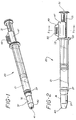
- a syringe nasal sprayer 20 of the present invention comprises an elongate barrel 21 having an open proximal end 22, a chamber 23 for retaining liquid and a tip portion 25 extending from a distal end 27 of the barrel having a passageway 28 therethrough communicating with the chamber.
- distal end is meant to refer to the end furthest from the person holding the syringe nasal sprayer whereas the term “proximal end” is meant to refer to the end closest to the holder of the syringe nasal sprayer.
- a stopper 29 is slidably positioned in fluid-tight engagement inside barrel 21 and is adopted to engage an elongate plunger rod 31 to facilitate its operation.
- the plunger rod projects proximally from the stopper and extends outwardly from the open proximal end of the barrel.
- the plunger rod is accessible outside of the proximal end of the barrel and is provided to move the stopper along the barrel to force liquid out of the chamber through the passageway.
- the stopper is capable of moving liquid from chamber 23 through passageway 28 upon its movement toward distal end 27 of the barrel.
- the stopper contains an internal thread (not shown) which engages an external thread (not shown) on the plunger rod.
- a disc-shaped plunger rod flange 32 is provided on the proximal end of the plunger rod to perform several functions.
- One such function is that flange 32 is a convenient structure for applying forces to move the plunger rod with respect to the barrel.
- the large surface area of the flange reduces the pressure on the fingers while delivering medication through the nasal sprayer.
- a stopper flange 33 at the distal end of the plunger rod is provided to supply a large surface area to transmit force from the plunger rod to the stopper in a direction toward the stopper, without damaging the stopper. It will be apparent to one skilled in the art that there are numerous constructions that can be used to join a stopper and a plunger rod and that the arrangement described herein is exemplary of these many possibilities. Also, it is within the purview of this invention to include a one-piece plunger rod-stopper assembly.
- a therapeutic liquid such as liquid medication 35 is contained within chamber 23.
- a spray nozzle 37 extends outwardly from the tip portion of the barrel and includes a conduit 39 therethrough in fluid communication with passageway 28.
- the spray nozzle includes a distal end 40 having a spray aperture 41 in fluid communication with conduit 39.
- the spray nozzle of the present invention is different from nozzles in prior art syringes having spray adapters in that the instant spray nozzle includes a means for preventing unpressurized liquid in the chamber from flowing through the spray aperture while allowing liquid under pressure in chamber 23 to flow distally through the conduit and spray aperture 41.
- This one-way valve feature allows the syringe nasal sprayer of the instant invention to be prefilled by a pharmaceutical manufacturer or in the hospital pharmacy and to be used at a future time or date.
- the one-way valve feature isolates the contents of the syringe from the environment and eliminates the need for other mechanisms to preclude flow through the distal end of the nasal sprayer.
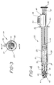
- the spray nozzle of this embodiment comprises two components, a cap 38 and a flexible valve 45.
- Cap 38 is secured to tip portion 25 of the barrel by virtue of an interference fit between enlarged portion 43 of tip 25 and interior surface 44 of the cap.
- the interference fit between the barrel, which is preferably made of glass, and the cap, which is preferably plastic, is a preferred way of joining these components. It should be noted that many materials are suitable for the barrel and for the cap and that numerous joining methods such as adhesive, heat sealing, and the like are all within the purview of the instant invention.
- Flexible valve 45 is contained within the cap between tip portion 25 and distal end 40 of the cap. Flexible valve 45 interacts with cap 38 to allow liquid under pressure in the chamber to flow distally through spray aperture 41 preventing unpressurized liquid in the chamber from flowing through the aperture.
- the valve in this preferred embodiment is a skirt valve having a circumferential skirt 46 which will partially collapse under the force of pressurized liquid in the chamber to allow liquid to flow from the chambers through the spray aperture. The skirt collapses by moving away from the side wall of the cap allowing liquid to pass through the liquid pressure created gap between the skirt and the cap.
- Another advantage of the spray nozzle of the instant invention is that a certain amount of pressure within chamber 23 is required before the valve will open. Accordingly, when the valve opens (i.e., the skirt collapses), the liquid is pressurized and is propelled past the valve through the spray aperture. If the pressure in the chamber becomes too low the valve will stop the flow of liquid, so that the valve acts as a means for protecting the contents of the syringe during storage and as a regulator to only allow pressurized liquid through the spray aperture.
- Another important feature and advantage of preferred embodiment of the present invention over the prior art is that it cannot be refilled after use. Accordingly, this invention protects the user from potential infection, contamination or injury caused by refilling, using improper procedures, the wrong drug or in a non-sterile or contaminated environment.
- the single-use feature or means of the preferred syringe nasal sprayer protects the patient by not allowing additional medication to be drawn into barrel chamber 23 through passageway 28 by placing the spray nozzle in fluid communication with a liquid medication and pulling the plunger in a proximal direction with respect to the barrel to create a sub-atmospheric pressure in the chamber.
- the syringe of the present invention is intended to be originally filled from the open proximal end of the barrel.
- the stopper is then inserted using an assembly tool which will allow air to escape while the stopper is being inserted into the barrel.
- the stopper can be inserted while the syringe and medication are in an evacuated chamber so that little or no air is trapped in the chamber when the stopper is inserted.
- a syringe so filled by a pharmaceutical manufacturer or other entity remote from the ultimate user is referred to as a prefilled or prefillable syringe.
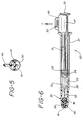
- the instant invention preferably includes dosage limiting housing 47 having a C-shaped cross-section, as best illustrated in Fig. 5.
- Housing 47 partially surrounds the plunger rod so that the housing will not fall off the plunger rod under its own weight but may be forceably removed from the plunger rod without eliminating the ability of the syringe nasal sprayer to deliver medication from the chamber through the aperture.
- the housing may be designed with a thin cross-section so that it will deflect and snap over the plunger rod or the plunger rod may be designed to deflect under the forces of the housing. Also, both elements may be designed to deflect partially during installation and removal of the housing.
- Housing 47 is adapted to interact between a radially extending projection on the plunger rod such as flange 32 and proximal end 22 of the barrel which includes a barrel flange 26 to limit the distal motion of the plunger rod with respect to the barrel.
- the length of housing 47 can correspond to one-half of the volume of therapeutic liquid in chamber 23.
- the syringe nasal sprayer can be inserted into one nostril of the patient while it is fully loaded as best illustrated in Fig. 4. Pressure on the plunger rod flange in a distal direction will cause therapeutic liquid to flow through the passageway into conduit 39 of the cap, deflecting the skirt portion 46 of the flexible valve, and through spray aperture 41.
- the plunger rod will move until its further distal motion is prevented by contact of the plunger rod flange 32 with housing 47 which in turn contacts barrel flange 26.
- the plunger rod can no longer be moved in a distal direction and approximately one-half of the therapeutic liquid still remains in the syringe.
- the user removes the syringe nasal sprayer from the one nostril.
- the user then pulls the housing in direction T, as illustrated in Fig. 6 to remove the housing from the plunger rod.
- a finger tab portion 49 is provided.
- finger tab 49 includes ribs 50 on both sides of the finger tab to facilitate gripping the tab. The tab once so gripped can be pulled in direction T to remove the housing from the plunger rod.
- the syringe nasal sprayer may now be placed so that the spray nozzle is in the other nostril of the patient and the remaining half of the therapeutical liquid may be delivered.
- the dosage limiting housing of the present invention is an important advantage of the instant syringe nasal sprayer over prior art devices.
- the housing does not necessarily have to divide the dose into one half portions but can be sized to facilitate any sequence which is therapeutically useful for two subsequent doses.
- a housing can also be provided which is equivalent to the full dose of therapeutic liquid in the chamber so that it is impossible to deliver any therapeutic liquid until the housing is removed. This feature is desirable if the syringe nasal sprayer will be subject to extreme forces and conditions between filling and time of use because it physically prevents the forward distal motion of the plunger rod with respect to the barrel until time of use.
- Multiple housings can also be provided. For example, two housings, each sized to prevent delivery of one-half of the dose can be provided so that the syringe nasal sprayer will be protected from forces which could move the plunger rod during shipping and will be able to deliver two approximately equal doses of therapeutic liquid at the time of use.
- the instant invention can be used in any medical application where medication or therapeutic liquid in a spray form is required such as for spraying liquid onto the eye or into an open wound or onto an irritated area such as a burn, and the nasal application described herein is exemplary of these many uses.
- Figs. 8-10 wherein an alternative syringe nasal sprayer 55 is illustrated.
- the structure of the syringe nasal sprayer is substantially similar to the syringe nasal sprayer of the embodiment of Figs. 1-7. Accordingly, substantially similar components that perform substantially similar functions will be numbered identically to the components of the embodiment of Figs. 1-7 except a suffix "a" will be used to identify those components in Figs. 8-10.
- syringe nasal sprayer 55 includes an elongate barrel 21a having an open proximal end 22a, a chamber 23a for retaining fluid and a tip portion 25a expending from a distal end 27a of the barrel having a passageway therethrough communicating with the chamber.
- a stopper 29a is slidably positioned in fluid-tight engagement inside the barrel, an elongate plunger rod 31a projects proximally from the stopper and extends outwardly from the open proximal end of the barrel.
- a spray nozzle 37a extends outwardly from the tip portion of the barrel and includes a conduit therethrough.
- the spray nozzle includes a cap 38a and a flexible valve 45a.
- the distal end of the cap includes a spray aperture 41a in fluid communication with conduit 39a.
- Internally positioned flexible valve 45a allows liquid under pressure in the chamber to flow distally through the conduit and through the aperture while preventing unpressurized liquid in the chamber from flowing through the aperture.
- cap portion 38a is integrally formed with tip portion 25a to produce an integral cap-tip member 57 thus eliminating another component.
- the barrel, the tip portion and the cap portion are all one-piece so that the barrel and flexible valve comprise two pieces.
- This embodiment includes means for holding the flexible valve in the cap portion so that sub-atmospheric pressure in chamber 23a will not pull the valve back into the chamber.
- two opposed projections 58 and 59 are formed inside the passageway to prevent withdrawal of the flexible valve from its distal position.
- Different means may be employed to position the valve depending on the materials and the valve design employed. These means include adhesive, ultrasonic welding and the like.
- the syringe nasal sprayer of the alternative embodiment of Figs. 8-10 functions in the same manner to deliver a therapeutic liquid as does the embodiment of the syringe nasal sprayer of Figs 1-7.
- the barrel of the present invention may be constructed of a wide variety of rigid materials such as metals, plastics, ceramics. Glass is preferred due to its long moisture vapor transmission rate and compatibility with many medication formulations.
- a wide variety of rigid materials are suitable for formation of the cap, plunger rod and housing. These materials includes metals or plastic with injection molded plastic being preferred.
- thermoplastic elastomers thermoplastic and thermosets are suitable for forming the flexible valve with thermoplastic and thermoplastic elastomers being preferred.
- a wide variety of materials such as natural rubber, synthetic rubber and thermoplastic elastomers are suitable for forming a stopper with natural rubber and butyl rubber being preferred.
- the present invention provides a straight-forward, reliable, easily fabricated syringe sprayer which provides the simplicity, ability to store therapeutic liquids and efficiency of a syringe in a device capable of delivering medication in the form of a spray without the use of complex difficult to use medication wasting adapters and without requiring further assembly at time of use which can lead to contamination and misuse.
- the present invention includes one-way valve features to prevent refilling the syringe after use.
- the present invention also provides structure to control the amount of medication delivered to each nostril and to control the total amount of liquid delivered.
Landscapes
- Health & Medical Sciences (AREA)
- Engineering & Computer Science (AREA)
- Life Sciences & Earth Sciences (AREA)
- Animal Behavior & Ethology (AREA)
- Public Health (AREA)
- Heart & Thoracic Surgery (AREA)
- Hematology (AREA)
- Anesthesiology (AREA)
- Veterinary Medicine (AREA)
- General Health & Medical Sciences (AREA)
- Biomedical Technology (AREA)
- Bioinformatics & Cheminformatics (AREA)
- Pulmonology (AREA)
- Biophysics (AREA)
- Mechanical Engineering (AREA)
- Otolaryngology (AREA)
- Vascular Medicine (AREA)
- Infusion, Injection, And Reservoir Apparatuses (AREA)
Claims (10)
- Zerstäuber-Spritze mit:- einem länglichen Zylinder (21) mit einem offenen proximalen Ende (22), einer Kammer (23) zur Aufnahme von Fluid und einem vom distalen Ende (27) des Zylinders (21) abstehenden Spitzenbereich (25) mit einem durch diesen hindurchgehenden Durchlaß (28), der mit der Kammer (23) in Verbindung steht;- einem gleitend verschiebbar in fluiddichtem Angriff in dem Zylinder (21) angeordneten Stopfen (29);- einer länglichen Kolbenstange (31), die proximal von dem Stopfen (29) absteht und sich von dem proximalen Ende (22) des Zylinders (21) nach außen erstreckt; und- einer sich vom Spitzenbereich (25) des Zylinders (21) nach außen erstreckenden Zerstäuberdüse (37) mit einem sich durch diese hindurch erstreckenden Kanal (39), der mit dem Durchlaß (28) in Fluidverbindung steht, wobei ein distales Ende (40) der Düse (37) eine Zerstäubungsöffnung (41) aufweist, die in Fluidverbindung mit dem Kanal (39) steht;dadurch gekennzeichnet, daß
die Düse (37) eine interne Ventileinrichtung (45) aufweist, die es ermöglicht, daß in der Kammer (23) befindliche unter Druck stehende Flüssigkeit distal durch den Kanal (39) und die Öffnung (41) fließt, während sie nicht druckbeaufschlagte Flüssigkeit in der Kammer (23) am Fließen durch die Öffnung (41) hindert. - Zerstäuber-Spritze nach Anspruch 1, bei der die innere Ventileinrichtung (45) eine in einer Richtung wirkende Ventileinrichtung zum Verhindern des Fließens von Flüssigkeit durch den Kanal (39) in proximaler Richtung zur Kammer (23) aufweist.
- Zerstäuber-Spritze nach Anspruch 1 oder 2, ferner mit einer Dosisbegrenzungseinrichtung zum Verhindern der Ausgabe einer vorbestimmten Menge der Flüssigkeit in der Kammer (23) durch den Durchlaß (28) durch Begrenzen der distalen Bewegung der Kolbenstange (31) in bezug auf den Zylinder (21), wobei die Dosisbegrerizungseinrichtung ferner eine diese außer Funktion setzende Einrichtung aufweist, um die Ausgabe sämtlicher in der Kammer (23) befindlicher Flüssigkeit zu ermöglichen.
- Zerstäuber-Spritze nach Anspruch 3, bei der die Dosisbegrenzungseinrichtung die Ausgabe ungefähr der Hälfte der Flüssigkeit in der Kammer (23) verhindert.
- Zerstäuber-Spritze nach Anspruch 3, bei der die Dosisbegrenzungseinrichtung die Ausgabe ungefähr der gesamten Flüssigkeit in der Kammer (23) verhindert.
- Zerstäuber-Spritze nach einem der Ansprüche 1-5, bei der die Kolbenstange (31) einen sich radial erstreckenden Vorsprung (32) aufweist, der mit der Dosisbegrenzungseinrichtung zusammenwirkt, um eine weitere distale Bewegung der Kolbenstange (31) in bezug auf den Zylinder (21) zu verhindern.
- Zerstäuber-Spritze nach einem der Ansprüche 1 bis 6, bei der die Dosisbegrenzungseinrichtung ein längliches Gehäuse (47) mit C-förmigem Querschnitt aufweist, wobei das Gehäuse (47) die Kolbenstange (31) teilweise umgibt, so daß das Gehäuse (47) nicht durch sein Eigengewicht von der Kolbenstange (31) herabfällt, jedoch zwangsweise von der Kolbenstange (31) abnehmbar ist, ohne die Fähigkeit der Zerstäuber-Spritze zur Ausgabe von Medikamenten aus der Kammer (23) durch die Öffnung (41) zu eliminieren, wobei das Gehäuse (47) derart ausgebildet ist, daß es mit dem sich radial erstreckenden Vorsprung (32) und dem proximalen Ende des Zylinders (21) zum Begrenzen der distalen Bewegung der Kolbenstange (31) in bezug auf den Zylinder (21) zusammenwirkt.
- Zerstäuber-Spritze nach einem der Ansprüche 1 - 7, bei der die Zerstäuberdüse (37) aufweist: eine Kappe (38) mit einem offenen proximalen Ende und einem distalen Ende (40), das die Zerstäubungsöffnung (41) aufweist, wobei die Kappe (38) an dem Spitzenbereich (25) befestigt ist; und ein flexibles Ventil (45) in der Kappe (38) zwischen dem Spitzenbereich (25) und dem distalen Ende (40) der Kappe (38), wobei das Ventil (45) mit der Kappe (38) derart zusammenwirkt, daß es das Fließen von in der Kammer (23) befindlicher druckbeaufschlagter Flüssigkeit in distaler Richtung durch die Zerstäubungsöffnung (41) ermöglicht, während das Fließen in der Kammer (23) befindlicher nicht druckbeaufschlagter Flüssigkeit durch die Öffnung (41) verhindert ist.
- Zerstäuber-Spritze nach einem der Ansprüche 1-7, bei der die Zerstäuberdüse (37a) aufweist: einen Kappenteil (38a) mit einem distalen Ende, das die Zerstäubungsöffnung (41a) aufweist, wobei das Kappenteil (38a) einstückig mit dem Spitzenbereich (25a) des Zylinders (21a) ausgebildet ist; ein flexibles Ventil (45a) in der Kappe (38a) und einer Einrichtung (58, 59) zum Halten des Ventils (45a) in der Kappe (38a).
- Zerstäuber-Spritze nach einem der Ansprüche 1-9, bei der das Ventil (45; 45a) ein Schürzenventil ist, das derart ausgerichtet ist, daß das Schürzenventil unter der Kraft von druckbeaufschlagter Flüssigkeit in der Kammer (23; 23a) teilweise zusammenklappt, um so das Fließen von Flüssigkeit aus der Kammer (23; 23a) durch die Zerstäubungsöffnung (41; 41a) zu ermöglichen.
Applications Claiming Priority (2)
| Application Number | Priority Date | Filing Date | Title |
|---|---|---|---|
| US742675 | 1991-08-07 | ||
| US07/742,675 US5601077A (en) | 1991-08-07 | 1991-08-07 | Nasal syringe sprayer with removable dose limiting structure |
Publications (3)
| Publication Number | Publication Date |
|---|---|
| EP0526824A2 EP0526824A2 (de) | 1993-02-10 |
| EP0526824A3 EP0526824A3 (en) | 1993-03-31 |
| EP0526824B1 true EP0526824B1 (de) | 1996-06-05 |
Family
ID=24985781
Family Applications (1)
| Application Number | Title | Priority Date | Filing Date |
|---|---|---|---|
| EP92112879A Expired - Lifetime EP0526824B1 (de) | 1991-08-07 | 1992-07-29 | Spritze mit Zerstäuber |
Country Status (7)
| Country | Link |
|---|---|
| US (1) | US5601077A (de) |
| EP (1) | EP0526824B1 (de) |
| JP (1) | JPH0613054B2 (de) |
| AU (1) | AU657979B2 (de) |
| CA (1) | CA2074219C (de) |
| DE (1) | DE69211244T2 (de) |
| ES (1) | ES2088057T3 (de) |
Cited By (3)
| Publication number | Priority date | Publication date | Assignee | Title |
|---|---|---|---|---|
| EP3162402A4 (de) * | 2014-06-25 | 2018-03-07 | Toko Yakuhin Kogyo Kabushiki Kaisha | Nasenspraydüse für medizinische spritze |
| WO2022049080A1 (en) * | 2020-09-01 | 2022-03-10 | Janssen Pharmaceutica, N.V. | Drug syringes with a mechanical stop for a second dose |
| US12576219B2 (en) | 2019-11-28 | 2026-03-17 | Wuxi Nest Biotechnology Co., Ltd | Spraying assembly |
Families Citing this family (112)
| Publication number | Priority date | Publication date | Assignee | Title |
|---|---|---|---|---|
| US7628339B2 (en) | 1991-04-24 | 2009-12-08 | Novartis Pharma Ag | Systems and methods for controlling fluid feed to an aerosol generator |
| US6540154B1 (en) * | 1991-04-24 | 2003-04-01 | Aerogen, Inc. | Systems and methods for controlling fluid feed to an aerosol generator |
| US5318016A (en) * | 1993-03-30 | 1994-06-07 | We Pharmaceuticals, Inc. | Inhalation device |
| PT689874E (pt) * | 1994-06-28 | 2002-03-28 | Aventis Behring Gmbh | Dispositivo para a pulverizacao de uma mistura de dois componentes |
| DE69605025T2 (de) * | 1995-03-14 | 2000-07-20 | Siemens Ag | Ultraschallzerstäuber mit abnehmbarer präzisionsdosiereinheit |
| US5970974A (en) * | 1995-03-14 | 1999-10-26 | Siemens Aktiengesellschaft | Dosating unit for an ultrasonic atomizer device |
| US6205999B1 (en) | 1995-04-05 | 2001-03-27 | Aerogen, Inc. | Methods and apparatus for storing chemical compounds in a portable inhaler |
| US6085740A (en) | 1996-02-21 | 2000-07-11 | Aerogen, Inc. | Liquid dispensing apparatus and methods |
| US5758637A (en) | 1995-08-31 | 1998-06-02 | Aerogen, Inc. | Liquid dispensing apparatus and methods |
| JP3280550B2 (ja) * | 1995-10-09 | 2002-05-13 | 株式会社資生堂 | カートリッジ式注射器のストッパー機構 |
| AUPN976496A0 (en) | 1996-05-10 | 1996-05-30 | Glaxo Wellcome Australia Ltd | Unit dose dispensing device |
| EP0821975A1 (de) * | 1996-07-31 | 1998-02-04 | Novartis AG (Novartis SA) (Novartis Inc.) | Dosiervorrichtung für fliessfähige Stoffe |
| US6109484A (en) * | 1997-03-14 | 2000-08-29 | Sun Medical Co Ltd | Dropping container |
| US5951526A (en) * | 1997-09-24 | 1999-09-14 | Korisch; Marina | Syringe holder with integral dose divider |
| US20050137566A1 (en) * | 2003-12-23 | 2005-06-23 | Fowles Thomas A. | Sliding reconstitution device for a diluent container |
| FR2793708B1 (fr) * | 1999-05-21 | 2001-08-03 | Valois Sa | Dispositif de distribution de produit fluide |
| US6235177B1 (en) * | 1999-09-09 | 2001-05-22 | Aerogen, Inc. | Method for the construction of an aperture plate for dispensing liquid droplets |
| US6398774B1 (en) * | 1999-09-29 | 2002-06-04 | Heska Corporation | Intranasal delivery system |
| US7678087B2 (en) * | 1999-09-29 | 2010-03-16 | Heska Corporation | Equine intranasal delivery system |
| USD448474S1 (en) | 1999-10-14 | 2001-09-25 | Becton, Dickinson And Company | Drug container holder |
| USD446578S1 (en) | 1999-10-14 | 2001-08-14 | Becton, Dickinson And Company | Drug container holder |
| USD447559S1 (en) | 1999-10-14 | 2001-09-04 | Becton, Dickinson And Company | Drug container holder |
| USD463546S1 (en) | 1999-10-14 | 2002-09-24 | Becton Dickinson And Company | Drug container holder |
| ES2214204T3 (es) | 1999-10-14 | 2004-09-16 | Becton, Dickinson And Company | Dispositivo de administracion nasal que incluye una boquilla de pulverizacion. |
| US6382204B1 (en) | 1999-10-14 | 2002-05-07 | Becton Dickinson And Company | Drug delivery system including holder and drug container |
| US6302101B1 (en) * | 1999-12-14 | 2001-10-16 | Daniel Py | System and method for application of medicament into the nasal passage |
| US6644305B2 (en) | 2000-04-14 | 2003-11-11 | Trudell Medical International | Nasal inhaler |
| US7600511B2 (en) * | 2001-11-01 | 2009-10-13 | Novartis Pharma Ag | Apparatus and methods for delivery of medicament to a respiratory system |
| MXPA02010884A (es) * | 2000-05-05 | 2003-03-27 | Aerogen Ireland Ltd | Aparato y metodo para el suministro de medicamentos al sistema respiratorio. |
| US7100600B2 (en) * | 2001-03-20 | 2006-09-05 | Aerogen, Inc. | Fluid filled ampoules and methods for their use in aerosolizers |
| US7971588B2 (en) * | 2000-05-05 | 2011-07-05 | Novartis Ag | Methods and systems for operating an aerosol generator |
| US6948491B2 (en) * | 2001-03-20 | 2005-09-27 | Aerogen, Inc. | Convertible fluid feed system with comformable reservoir and methods |
| US8336545B2 (en) * | 2000-05-05 | 2012-12-25 | Novartis Pharma Ag | Methods and systems for operating an aerosol generator |
| EP1211628B1 (de) * | 2000-11-30 | 2014-05-14 | Canon Kabushiki Kaisha | Inhalator und Ausstosskopfkontrolverfahren |
| US6644309B2 (en) | 2001-01-12 | 2003-11-11 | Becton, Dickinson And Company | Medicament respiratory delivery device and method |
| US6443152B1 (en) | 2001-01-12 | 2002-09-03 | Becton Dickinson And Company | Medicament respiratory delivery device |
| US6722364B2 (en) | 2001-01-12 | 2004-04-20 | Becton, Dickinson And Company | Medicament inhalation delivery devices and methods for using the same |
| US20020174865A1 (en) * | 2001-03-01 | 2002-11-28 | Gatton Brian M. | Nasal spray apparatus and system |
| US6732944B2 (en) * | 2001-05-02 | 2004-05-11 | Aerogen, Inc. | Base isolated nebulizing device and methods |
| JP2002336349A (ja) * | 2001-05-21 | 2002-11-26 | Ohta Pharmaceut Co Ltd | 薬剤注入用容器 |
| GB2377176B (en) * | 2001-06-30 | 2004-10-20 | John Leyshon Maddocks | Devices for administering material |
| US7021561B2 (en) * | 2001-12-18 | 2006-04-04 | Becton, Dickinson And Company | Spray device and method |
| US20050205089A1 (en) * | 2002-01-07 | 2005-09-22 | Aerogen, Inc. | Methods and devices for aerosolizing medicament |
| US7677467B2 (en) * | 2002-01-07 | 2010-03-16 | Novartis Pharma Ag | Methods and devices for aerosolizing medicament |
| EP1471960B1 (de) | 2002-01-07 | 2019-03-13 | Novartis AG | Vorrichtungen zur vernebelung von flüssigkeiten zur inhalation |
| DE10200595A1 (de) * | 2002-01-10 | 2003-07-31 | Aero Pump Gmbh | Betätigungskopf einer Saug-Druck-Pumpe zum Ausspritzen eines Produkts aus einem Behältnis |
| EP1474196B1 (de) | 2002-01-15 | 2016-08-17 | Novartis AG | Verfahren und systeme zum bedienen eines aerosol-erzeugers |
| US6698429B2 (en) | 2002-03-15 | 2004-03-02 | Wolfe Tory Medical, Inc. | Medical atomizer |
| US6786883B2 (en) | 2002-04-15 | 2004-09-07 | Ronald D. Shippert | Applicator for insertion of cargo into a body cavity |
| US20070044792A1 (en) * | 2005-08-30 | 2007-03-01 | Aerogen, Inc. | Aerosol generators with enhanced corrosion resistance |
| AU2003256253A1 (en) * | 2002-05-20 | 2003-12-02 | Aerogen, Inc. | Aerosol for medical treatment and methods |
| US20040039352A1 (en) * | 2002-06-28 | 2004-02-26 | Paul Bergeson | Nasal dosing device |
| WO2004004811A1 (ja) * | 2002-07-02 | 2004-01-15 | Terumo Kabushiki Kaisha | シリンジおよびプレフィルドシリンジ |
| FR2845016B1 (fr) | 2002-09-27 | 2004-12-03 | Becton Dickinson France | Dispositif de pulverisation ou d'injection permettant de delivrer au moins deux doses determinees de produit |
| GB0302536D0 (en) * | 2003-02-04 | 2003-03-12 | Bespak Plc | Container |
| DE10318797A1 (de) * | 2003-04-25 | 2004-11-11 | Alfred Von Schuckmann | Spender mit einer die Spendeöffnung abdeckenden Schutzkappe |
| US7389947B2 (en) * | 2003-07-11 | 2008-06-24 | Wolfe Tory Medical, Inc. | Pump-bottle atomizer |
| US8616195B2 (en) * | 2003-07-18 | 2013-12-31 | Novartis Ag | Nebuliser for the production of aerosolized medication |
| US7172071B2 (en) * | 2003-08-05 | 2007-02-06 | Biomet Manufacturing Corp. | Method and apparatus for use of a vacuum package for allograft material |
| US8210166B2 (en) * | 2003-12-16 | 2012-07-03 | Wolfe Tory Medical, Inc. | Vial multi-access adapter |
| US20050209555A1 (en) * | 2004-03-18 | 2005-09-22 | Lance Middleton | Systems and methods for mixing fluids |
| US7946291B2 (en) | 2004-04-20 | 2011-05-24 | Novartis Ag | Ventilation systems and methods employing aerosol generators |
| US7267121B2 (en) * | 2004-04-20 | 2007-09-11 | Aerogen, Inc. | Aerosol delivery apparatus and method for pressure-assisted breathing systems |
| KR101226995B1 (ko) * | 2004-04-20 | 2013-01-28 | 노바르티스 아게 | 압력 보조식 호흡 장치용 에어로졸 전달 장치 |
| US7290541B2 (en) * | 2004-04-20 | 2007-11-06 | Aerogen, Inc. | Aerosol delivery apparatus and method for pressure-assisted breathing systems |
| KR101225216B1 (ko) * | 2004-12-01 | 2013-01-22 | 아큐샷 인크. | 무침 주사기 |
| USD556320S1 (en) * | 2005-04-21 | 2007-11-27 | Rexam Dispensing Systems | Nasal dispenser |
| USD556903S1 (en) * | 2005-05-03 | 2007-12-04 | Rexam Dispensing Systems | Nasal dispenser |
| BRPI0611198B1 (pt) * | 2005-05-25 | 2018-02-06 | Aerogen, Inc. | Vibration systems and methods |
| JP4733617B2 (ja) * | 2006-11-06 | 2011-07-27 | 日本特殊陶業株式会社 | 医療用ペースト注入混練器及び医療用ペースト注入混練器材 |
| US9707367B2 (en) * | 2007-06-21 | 2017-07-18 | Resmed Limited | Auto-adjusting mask stabilizer |
| JP4938593B2 (ja) * | 2007-08-27 | 2012-05-23 | 株式会社大塚製薬工場 | 薬液噴霧キット |
| SG189771A1 (en) * | 2008-01-11 | 2013-05-31 | Ucb Pharma Sa | Systems and methods for administering medication |
| WO2009095735A1 (en) | 2008-01-30 | 2009-08-06 | Becton Dickinson France | Dose dividing delivery device |
| FR2927552B1 (fr) * | 2008-02-19 | 2011-05-27 | Becton Dickinson France | Pulverisateur, notamment a usage medical |
| JP5095500B2 (ja) * | 2008-05-23 | 2012-12-12 | 株式会社トップ | ガラス製シリンジにおけるプランジャの位置決め部材 |
| PL3581223T3 (pl) | 2008-07-18 | 2024-11-25 | UCB Biopharma SRL | Systemy automatycznego podawania leków |
| USD641078S1 (en) | 2008-12-29 | 2011-07-05 | Ucb Pharma, S.A. | Medical syringe with needle tip cap |
| US20100305130A1 (en) * | 2009-06-01 | 2010-12-02 | PHILLIPS Thomas | Nasal spray device and method of use thereof |
| US8916171B2 (en) * | 2010-04-27 | 2014-12-23 | Topical Sinus Therapeutics, Inc. | Topical delivery of viscous medications for the treatment of diseases associated with chronic sinusitis |
| FR2962351B1 (fr) * | 2010-07-09 | 2015-01-16 | Valois Sas | Tete de pulverisation pour dispositif de distribution de produit fluide. |
| JP5858042B2 (ja) * | 2011-05-13 | 2016-02-10 | ニプロ株式会社 | 鼻腔投与容器 |
| GB2499611B (en) * | 2012-02-22 | 2015-09-16 | Consort Medical Plc | Valved container assembly |
| CA152090S (en) * | 2012-03-22 | 2013-08-12 | Geistlich Pharma Ag | Syringe |
| GB2503028B (en) * | 2012-06-15 | 2018-10-24 | Consort Medical Plc | Valved container assembly |
| KR102357044B1 (ko) | 2012-12-04 | 2022-02-08 | 말린크로트 파마슈티칼스 아일랜드 리미티드 | 일산화질소 전달 동안 투약량의 희석을 최소화하기 위한 캐뉼라 |
| US9795756B2 (en) | 2012-12-04 | 2017-10-24 | Mallinckrodt Hospital Products IP Limited | Cannula for minimizing dilution of dosing during nitric oxide delivery |
| WO2015085215A1 (en) | 2013-12-06 | 2015-06-11 | Teleflex Medical Incorporated | Dose divider syringe |
| FR3016304B1 (fr) * | 2014-01-13 | 2018-03-09 | Aptar France Sas | Ensemble de distribution de produit fluide et procede d'utilisation d'un tel ensemble. |
| KR102491446B1 (ko) | 2014-06-25 | 2023-01-20 | 도코 야쿠힌 고교 가부시키가이샤 | 인플루엔자 백신의 경비접종 시스템 |
| EP3171917B1 (de) | 2014-07-24 | 2024-09-25 | Teleflex Medical Incorporated | Dosisteiler-spritze |
| US10258502B2 (en) * | 2014-09-18 | 2019-04-16 | Orbit Biomedical Limited | Therapeutic agent delivery device |
| CA2964457A1 (en) * | 2014-10-13 | 2016-04-21 | The Werc Shop, LLC | Metered dosing method and mechanisms thereof |
| AU2016223140B2 (en) * | 2015-02-24 | 2018-05-10 | Teleflex Medical Incorporated | Dose divider syringe |
| CN107771093B (zh) * | 2015-07-03 | 2021-06-15 | 弗罗桑医疗设备公司 | 用于混合两种组分和用于在存储条件下保持真空的注射器 |
| FR3057169B1 (fr) * | 2016-10-11 | 2022-04-01 | Crossject | Buse d’injection pour dispositif d’injection sans aiguille |
| JP6558392B2 (ja) * | 2017-04-04 | 2019-08-14 | ニプロ株式会社 | シリンジ型噴出装置 |
| KR101964422B1 (ko) * | 2017-05-16 | 2019-04-01 | (주)제이엠씨코리아 (Jmc Korea Co.,Ltd.) | 약물 방출용 분무 카데터 |
| CN111246841B (zh) * | 2017-10-20 | 2024-07-26 | 奇斯药制品公司 | 包含阿片样物质受体激动剂作为活性成分的药物制剂、其制备方法和治疗用途 |
| WO2019152817A1 (en) * | 2018-02-01 | 2019-08-08 | Mcmahon Douglas F | Compact kit for injecting liquid medication |
| KR102149190B1 (ko) | 2018-04-09 | 2020-08-28 | 경상대학교산학협력단 | 액중 방전 마이크로젯 약물 전달장치 |
| JP7266971B2 (ja) * | 2018-05-24 | 2023-05-01 | ニプロ株式会社 | シリンジ型噴出装置 |
| AU2021237233A1 (en) * | 2020-03-17 | 2022-08-25 | Amgen Inc. | Controlled dispense syringe |
| USD975274S1 (en) * | 2020-06-26 | 2023-01-10 | Board Of Regents Of The University Of Nebraska | Precision syringe plunger |
| CN113134151A (zh) * | 2021-04-22 | 2021-07-20 | 西安市第三医院 | 一种耳鼻喉科治疗用给药装置 |
| DE102021112962A1 (de) * | 2021-05-19 | 2022-11-24 | F+K Innovationen Gmbh & Co. Kg | BI-Dose-Vorrichtung |
| WO2023013515A1 (ja) * | 2021-08-02 | 2023-02-09 | ニプロ株式会社 | 噴霧器 |
| EP4201457A1 (de) * | 2021-12-22 | 2023-06-28 | Gerresheimer Regensburg GmbH | Zerstäubungsmittel |
| EP4245336A1 (de) | 2022-03-15 | 2023-09-20 | Becton Dickinson France | Injektionsvorrichtung mit einem dosiseinstellelement |
| CN117504070A (zh) * | 2022-09-23 | 2024-02-06 | 天舟医疗(苏州)有限公司 | 鼻腔喷雾给药装置及包括该装置的喷雾系统 |
| CN116077816B (zh) * | 2023-04-11 | 2023-06-16 | 无锡耐思生命科技股份有限公司 | 一种雾化喷头和喷雾装置 |
| FR3153608B1 (fr) | 2023-10-03 | 2025-10-24 | Aptar France Sas | Dispositif de distribution de produit fluide |
Family Cites Families (15)
| Publication number | Priority date | Publication date | Assignee | Title |
|---|---|---|---|---|
| US3373743A (en) * | 1963-11-29 | 1968-03-19 | Dentists Supply Co | Disposable hypodermic syringe |
| US3502078A (en) * | 1967-11-15 | 1970-03-24 | Donald E Hill | Dual-tipped nasal syringe and aspirating device |
| US3874380A (en) * | 1974-05-28 | 1975-04-01 | Smithkline Corp | Dual nozzle intranasal delivery device |
| US3874381A (en) * | 1974-05-28 | 1975-04-01 | Smithkline Corp | Dual nozzle intranasal delivery device |
| US4112924A (en) * | 1977-04-07 | 1978-09-12 | Louis Thomas Ferrara | Blood collection valve |
| US4493348A (en) * | 1981-06-29 | 1985-01-15 | Pur/Acc Corporation | Method and apparatus for orally dispensing liquid medication |
| FR2573819B1 (fr) * | 1984-11-23 | 1989-03-10 | Aerosol Inventions Dev | Procede pour limiter le debit d'une pompe, petite pompe manuelle et seringue compte-gouttes mettant en oeuvre ce procede |
| US4767416A (en) * | 1986-12-01 | 1988-08-30 | Johnson & Johnson Patient Care, Inc. | Spray nozzle for syringe |
| FR2625981B1 (fr) | 1988-01-15 | 1990-04-27 | Valois Sa | Dispositif de pulverisation du contenu d'une ampoule cylindrique |
| DE3810262A1 (de) * | 1988-03-25 | 1989-10-12 | Henning Berlin Gmbh | Vorrichtung zur dosierten verabreichung eines fluessigen arzneimittels |
| FR2635084B1 (fr) * | 1988-08-08 | 1991-04-12 | Sofab | Embouts de distributeurs |
| US4923448A (en) * | 1988-12-06 | 1990-05-08 | Mark Anderson | Syringe with spray nozzle tip |
| US4919167A (en) * | 1989-03-17 | 1990-04-24 | Manska Wayne E | Check valve |
| DE4016126A1 (de) * | 1990-04-17 | 1991-10-24 | Coster Tecnologie Speciali Spa | Vorrichtung zur transnasalen oder oralen verabreichung von medikamenten o. dgl. |
| US5098405A (en) * | 1991-01-31 | 1992-03-24 | Becton, Dickinson And Company | Apparatus and method for a side port cathether adapter with a one piece integral combination valve |
-
1991
- 1991-08-07 US US07/742,675 patent/US5601077A/en not_active Expired - Lifetime
-
1992
- 1992-07-20 CA CA002074219A patent/CA2074219C/en not_active Expired - Lifetime
- 1992-07-23 AU AU20519/92A patent/AU657979B2/en not_active Expired
- 1992-07-29 ES ES92112879T patent/ES2088057T3/es not_active Expired - Lifetime
- 1992-07-29 DE DE69211244T patent/DE69211244T2/de not_active Expired - Lifetime
- 1992-07-29 EP EP92112879A patent/EP0526824B1/de not_active Expired - Lifetime
- 1992-08-06 JP JP4210357A patent/JPH0613054B2/ja not_active Expired - Lifetime
Cited By (4)
| Publication number | Priority date | Publication date | Assignee | Title |
|---|---|---|---|---|
| EP3162402A4 (de) * | 2014-06-25 | 2018-03-07 | Toko Yakuhin Kogyo Kabushiki Kaisha | Nasenspraydüse für medizinische spritze |
| RU2710346C2 (ru) * | 2014-06-25 | 2019-12-25 | Токо Якухин Когио Кабусики Кайся | Назальное распылительное сопло, используемое для медицинского шприца |
| US12576219B2 (en) | 2019-11-28 | 2026-03-17 | Wuxi Nest Biotechnology Co., Ltd | Spraying assembly |
| WO2022049080A1 (en) * | 2020-09-01 | 2022-03-10 | Janssen Pharmaceutica, N.V. | Drug syringes with a mechanical stop for a second dose |
Also Published As
| Publication number | Publication date |
|---|---|
| JPH05184674A (ja) | 1993-07-27 |
| CA2074219A1 (en) | 1993-02-08 |
| US5601077A (en) | 1997-02-11 |
| EP0526824A2 (de) | 1993-02-10 |
| DE69211244T2 (de) | 1996-10-02 |
| CA2074219C (en) | 1996-10-15 |
| DE69211244D1 (de) | 1996-07-11 |
| AU657979B2 (en) | 1995-03-30 |
| JPH0613054B2 (ja) | 1994-02-23 |
| EP0526824A3 (en) | 1993-03-31 |
| AU2051992A (en) | 1993-02-11 |
| ES2088057T3 (es) | 1996-08-01 |
Similar Documents
| Publication | Publication Date | Title |
|---|---|---|
| EP0526824B1 (de) | Spritze mit Zerstäuber | |
| CA2113953C (en) | Syringe needle isolation device | |
| EP1129786B1 (de) | System zur Verabreichung von Arzneimittlen mit einem Arzneimittelbehälter und dessen Halterung | |
| EP1092447B1 (de) | Nasales Verabreichungsgerät mit Zerstäuberdüse | |
| US7175609B1 (en) | Syringe and method of using | |
| US5779683A (en) | Injector module for a syringe and pre-filled syringe provided therewith | |
| EP1461102B1 (de) | Sprühvorrichtung und verfahren | |
| KR20110055518A (ko) | 재사용 가능한 자동-주사기 | |
| US20080071246A1 (en) | Injector apparatus and method of use | |
| US6277102B1 (en) | Hypodermic syringe system and method of manufacture | |
| HK1044298B (zh) | 药物分配器 | |
| US20040135002A1 (en) | Device for the spraying of fluids | |
| US5624407A (en) | Medication injecting device and accessories therefor | |
| JP2018524096A (ja) | 単回使用送達デバイス | |
| US20230330355A1 (en) | Single-Use Adapter Attached to Drug/Vaccine Vials Compatible with Hypodermic Needles to Enable Injection | |
| EP0372277A1 (de) | Verabreichungssystem für vorgefüllte Spritze |
Legal Events
| Date | Code | Title | Description |
|---|---|---|---|
| PUAI | Public reference made under article 153(3) epc to a published international application that has entered the european phase |
Free format text: ORIGINAL CODE: 0009012 |
|
| PUAL | Search report despatched |
Free format text: ORIGINAL CODE: 0009013 |
|
| AK | Designated contracting states |
Kind code of ref document: A2 Designated state(s): BE DE ES FR GB IT |
|
| AK | Designated contracting states |
Kind code of ref document: A3 Designated state(s): BE DE ES FR GB IT |
|
| 17P | Request for examination filed |
Effective date: 19930911 |
|
| 17Q | First examination report despatched |
Effective date: 19950124 |
|
| GRAH | Despatch of communication of intention to grant a patent |
Free format text: ORIGINAL CODE: EPIDOS IGRA |
|
| GRAH | Despatch of communication of intention to grant a patent |
Free format text: ORIGINAL CODE: EPIDOS IGRA |
|
| GRAA | (expected) grant |
Free format text: ORIGINAL CODE: 0009210 |
|
| AK | Designated contracting states |
Kind code of ref document: B1 Designated state(s): BE DE ES FR GB IT |
|
| REG | Reference to a national code |
Ref country code: ES Ref legal event code: BA2A Ref document number: 2088057 Country of ref document: ES Kind code of ref document: T3 |
|
| REF | Corresponds to: |
Ref document number: 69211244 Country of ref document: DE Date of ref document: 19960711 |
|
| ET | Fr: translation filed | ||
| REG | Reference to a national code |
Ref country code: ES Ref legal event code: FG2A Ref document number: 2088057 Country of ref document: ES Kind code of ref document: T3 |
|
| ITF | It: translation for a ep patent filed | ||
| PLBE | No opposition filed within time limit |
Free format text: ORIGINAL CODE: 0009261 |
|
| STAA | Information on the status of an ep patent application or granted ep patent |
Free format text: STATUS: NO OPPOSITION FILED WITHIN TIME LIMIT |
|
| 26N | No opposition filed | ||
| REG | Reference to a national code |
Ref country code: GB Ref legal event code: IF02 |
|
| PGFP | Annual fee paid to national office [announced via postgrant information from national office to epo] |
Ref country code: FR Payment date: 20110805 Year of fee payment: 20 |
|
| PGFP | Annual fee paid to national office [announced via postgrant information from national office to epo] |
Ref country code: ES Payment date: 20110726 Year of fee payment: 20 Ref country code: DE Payment date: 20110727 Year of fee payment: 20 Ref country code: GB Payment date: 20110725 Year of fee payment: 20 |
|
| PGFP | Annual fee paid to national office [announced via postgrant information from national office to epo] |
Ref country code: IT Payment date: 20110727 Year of fee payment: 20 Ref country code: BE Payment date: 20110728 Year of fee payment: 20 |
|
| REG | Reference to a national code |
Ref country code: DE Ref legal event code: R071 Ref document number: 69211244 Country of ref document: DE |
|
| BE20 | Be: patent expired |
Owner name: *BECTON DICKINSON AND CY Effective date: 20120729 |
|
| REG | Reference to a national code |
Ref country code: DE Ref legal event code: R071 Ref document number: 69211244 Country of ref document: DE |
|
| REG | Reference to a national code |
Ref country code: GB Ref legal event code: PE20 Expiry date: 20120728 |
|
| PG25 | Lapsed in a contracting state [announced via postgrant information from national office to epo] |
Ref country code: DE Free format text: LAPSE BECAUSE OF EXPIRATION OF PROTECTION Effective date: 20120731 Ref country code: GB Free format text: LAPSE BECAUSE OF EXPIRATION OF PROTECTION Effective date: 20120728 |
|
| REG | Reference to a national code |
Ref country code: ES Ref legal event code: FD2A Effective date: 20130801 |
|
| PG25 | Lapsed in a contracting state [announced via postgrant information from national office to epo] |
Ref country code: ES Free format text: LAPSE BECAUSE OF EXPIRATION OF PROTECTION Effective date: 20120730 |