EP0527089B1 - Verfahren und Gerät zur Bestimmung der horizontalen Leitfähigkeit und der vertikalen Leitfähigkeit von Erdformationen - Google Patents
Verfahren und Gerät zur Bestimmung der horizontalen Leitfähigkeit und der vertikalen Leitfähigkeit von Erdformationen Download PDFInfo
- Publication number
- EP0527089B1 EP0527089B1 EP92402243A EP92402243A EP0527089B1 EP 0527089 B1 EP0527089 B1 EP 0527089B1 EP 92402243 A EP92402243 A EP 92402243A EP 92402243 A EP92402243 A EP 92402243A EP 0527089 B1 EP0527089 B1 EP 0527089B1
- Authority
- EP
- European Patent Office
- Prior art keywords
- conductivity
- values
- horizontal
- vertical
- formation
- Prior art date
- Legal status (The legal status is an assumption and is not a legal conclusion. Google has not performed a legal analysis and makes no representation as to the accuracy of the status listed.)
- Expired - Lifetime
Links
Images


Classifications
-
- G—PHYSICS
- G01—MEASURING; TESTING
- G01V—GEOPHYSICS; GRAVITATIONAL MEASUREMENTS; DETECTING MASSES OR OBJECTS; TAGS
- G01V3/00—Electric or magnetic prospecting or detecting; Measuring magnetic field characteristics of the earth, e.g. declination, deviation
- G01V3/18—Electric or magnetic prospecting or detecting; Measuring magnetic field characteristics of the earth, e.g. declination, deviation specially adapted for well-logging
- G01V3/26—Electric or magnetic prospecting or detecting; Measuring magnetic field characteristics of the earth, e.g. declination, deviation specially adapted for well-logging operating with magnetic or electric fields produced or modified either by the surrounding earth formation or by the detecting device
- G01V3/28—Electric or magnetic prospecting or detecting; Measuring magnetic field characteristics of the earth, e.g. declination, deviation specially adapted for well-logging operating with magnetic or electric fields produced or modified either by the surrounding earth formation or by the detecting device using induction coils
-
- G—PHYSICS
- G01—MEASURING; TESTING
- G01V—GEOPHYSICS; GRAVITATIONAL MEASUREMENTS; DETECTING MASSES OR OBJECTS; TAGS
- G01V3/00—Electric or magnetic prospecting or detecting; Measuring magnetic field characteristics of the earth, e.g. declination, deviation
- G01V3/38—Processing data, e.g. for analysis, for interpretation, for correction
Definitions
- This invention relates to the field of earth borehole logging and, more particularly, to a method and apparatus for determining horizontal conductivity and vertical conductivity of earth formations.
- the resistivity of this sample measured with a current flowing along its axis is called the longitudinal (or horizontal) resistivity R h .
- the inverse of R h is the horizontal conductivity, ⁇ h .
- the resistivity measured with a current flowing along its axis is called the transversal (or vertical) resistivity R v .
- the inverse of R v is the vertical conductivity, ⁇ v .
- the anisotropy coefficient ⁇ by definition, is equal to R v / R h (0 r ⁇ h / ⁇ v ). Laboratory measurements have shown that ⁇ may range from 1 to about 2.5 in different shales.
- R v R v + R h .
- R 1 and R 2 can be determined from (1) and (2) if R h and R v are known.
- the logging apparatus disclosed in U.S. Patent No. 4,302,723 is one such apparatus which comprises a first transmitter coil having an axis substantially parallel to the borehole axis and a second transmitter coil having an axis which is substantially perpendicular to the borehole axis.
- the apparatus further comprises a receiver which incorporates first and second receiver coils having axes which are substantially mutually orthogonal and perpendicular to the borehole axis.
- the transmitter coils may be energized in a manner which permits the separate detection at the receivers of the currents induced in the earth formations by each of the two transmitter coils.
- the reactive components of the detected signals are used to obtain dip and/or anisotropy parameters of the formations.
- U.S. Patent No. 4,636,731 discloses a logging apparatus comprising two transmitter coils and two pairs of receiver coils.
- the transmitter coils alternately transmit electromagnetic energy into the earth formations and provide a control signal.
- Signals from the four receivers are processed to provide vertical and horizontal resistances of the earth formations.
- Equipment and techniques that determine horizontal and vertical conductivity (or anisotropy) by employing special equipment dedicated specifically to such purpose result in increased equipment cost and increased logging time and/or cost. It is among the objects of the present invention to provide an apparatus and technique for determining horizontal and vertical conductivity (or anisotropy determinable therefrom) using measurements that are often available from conventional types of equipment utilized for logging earth boreholes during drilling or by wireline.
- any references to determination or use of resistivity are intended to generically means conductivity as well, and vice versa. These quantities are reciprocals, and mention of one or the other herein is for convenience of description, and not intended in a limiting sense.
- the derived first and second formation conductivity values are obtained from measurements which are affected differently by the vertical and horizontal conductivities of the formations.
- the horizontal and vertical conductivity model values are modified as a function of the error values.
- the error values comprise a first error value that depends on the difference between the first composite conductivity value and the first derived formation conductivity value, and the second error value depends on the difference between the second composite conductivity value and the second derived formation conductivity value.
- a method for determining the horizontal conductivity and the vertical conductivity of earth formations surrounding a borehole including the following steps: a) deriving first and second formation conductivity values from measurements taken in the borehole, the derived first and second conductivity values being obtained from measurements which are affected differently by the vertical and horizontal conductivities of the formations; b) deriving an angle related to the dip of said formations; c) computing horizontal and vertical conductivity values from the derived first and second conductivity values and the derived angle; and d) outputting the horizontal and vertical conductivity values.
- the step of computing horizontal and vertical conductivity values includes storing a look-up table of values, and selecting values from the look-up table based on the derived first and second conductivity values and the derived angle.
- Fig. 1 is a diagram, partially in block form, of an apparatus that can be utilized in practicing an embodiment of the invention.
- Fig. 2 is simplified diagram, partially in block form, of an apparatus for measuring formation resistivity that can be utilized in an embodiment of the invention.
- Fig.s 3 and 4 are, respectively, graphs of relationships between measured attenuation and formation resistivity, and measured phase shift and formation resistivity.
- Fig. 5 shows a model space of the formations, with magnetic dipoles in the x and z directions.
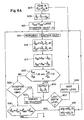
- Fig.s 6A and 6B placed one below another, illustrate a routine for programming a processor in accordance with an embodiment of the invention.
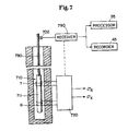
- Fig. 7 is a simplified diagram, partially in block form, of an induction logging apparatus that can be utilized in an embodiment of the invention.
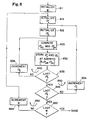
- Fig. 8 is a flow diagram of a routine for programming a processor to generate and store a look-up table useful in an embodiment of the invention.
- Fig. 9 is a flow diagram of a routine for programming a processor to use the look-up table in accordance with an embodiment of the invention.
- Drilling fluid or mud 26 is contained in a pit 27 in the earth.
- a pump 29 pumps the drilling fluid into the drill string via a port in the swivel 19 to flow downward through the center of drill string 12, as indicated by flow arrow 30.
- the drilling fluid exits the drill string via ports in the drill bit 15 and then circulates upward in the region between the outside of the drill string and the periphery of the borehole, as indicated by flow arrows 32.
- the drilling fluid thereby lubricates the bit and carries formation cuttings to the surface of the earth.
- the drilling fluid is returned to the pit 27 for recirculation.
- a bottom hole assembly 100 Mounted in conjunction with the drill bit 15 is a bottom hole assembly 100 that may include an optional directional drilling assembly 400 with a mud motor having a bent housing or an offset sub (not separately represented). Mounted above optional subassembly 400 is a formation resistivity (or conductivity) measuring apparatus 200 which is described further hereinbelow.
- a measurement and communications subassembly 500 is also provided and includes means, known in the art, for measuring and/or computing the direction and inclination of the bottom hole assembly, the rotational orientation of the bottom hole assembly ("tool face"), and, typically, other measurements which need not be summarized herein.
- the communications portion of the subassembly 500 may typically be a mud pulse telemetry system that includes a downhole transmitter for sending coded information, including measurement signals, uphole and surface instrumentation for detecting and decoding the information.
- a mud pulse telemetry system has an acoustic transmitter which employs a device known as a "mud siren” which includes a slotted stator and a slotted rotor that rotates and repeatedly interrupts the flow of drilling fluid to establish a desired acoustic wave signal in the drilling fluid.
- Driving electronics in subassembly 500 may typically include a suitable modulator, such as a phase shift keying (PSK) modulator, which conventionally produces driving signals for application to the mud transmitter.
- PSK phase shift keying
- Fig. 2 is a simplified representation of the formation resistivity (or conductivity) measuring subassembly 200 of the Fig. 1 apparatus.
- This subassembly known in the art, may be in accordance with apparatus described in U.S. Patent No. 4,899,112, which is incorporated herein by reference.
- the apparatus includes spaced apart transmitting antennas T 1 and T 2 mounted on a section of drill collar 210, and spaced apart receiving antennas R 1 and R 2 mounted between the transmitting antennas.
- the antennas are coils supported in insulating media in recesses in the drill collar.
- the downhole electronics typically contained in the drill collar 210 and represented in Fig.
- the block 220 include, inter alia, means for alternately energizing the transmitters with a signal having a frequency in the range about 0.1 MHz to 10 MHz, and typically about 2 MHz. Electromagnetic energy is transmitted into the formation and propagates therein. Energy shed back into the borehole is measured at the receiver pair, in a so-called differential receiver arrangement, to obtain a phase shift measurement and an attenuation measurement.
- the downhole subsystem further includes processor electronics, including a microprocessor with associated memory, timing, and interface circuitry, as described in the referenced U.S. Patent No. 4,899,112.] Also, the use of two transmitters provides borehole compensation, but measurements could be obtained using a single transmitter.
- Fig 3 represents the relationship between the measured attenuation and the attenuation-dependent resistivity, R ad , as described in the above-referenced U.S. Patent No. 4,899,112.
- Fig. 4 represents the relationship between the measured phase shift and the phase-shift-dependent resistivity, R ps as described in said referenced Patent.
- the illustrated exemplary graphs are for an embodiment with the receivers mounted on a 6.5 inch diameter drill collar, receiver spacings of 25 and 31 inches, and a transmitter frequency of 2 MHz.
- the plot of Fig. 3 can be utilized, for example, by entering the measured attenuation (minus a factor due to geometrical spreading loss) to read a corresponding value of R ad as determined by the curve.
- the plot of Fig. 4 can be utilized in similar fashion to obtain a value of R ps from a phase shift measurement.
- the referenced Patent indicates that a stored look-up table or stored polynomial curves can be used to automatically obtain values of R ad and/or R ps , and that correction for permittivity can also be implemented.
- the processor 95 can be programmed in the manner described in the referenced patent to obtain these values (and/or their inverses, the conductivities ⁇ ad and ⁇ ps ), or they can be computed downhole.
- the magnetic dipole 511 is oriented in the vertical direction and the magnetic dipole 512 is oriented in a direction in the horizontal plane (arbitrarily, the x direction, in this case).
- the voltages at the receivers can be derived as being equal to i ⁇ 2 ⁇ r 2 R R H ⁇ ⁇ n ⁇ where n ⁇ is the direction along the axis of the tool, r R is the radius of the receiver coil and R is the number of turns on the receiver.
- M ⁇ R 2 T TI where R T is the radius of the transmitter coil, T is the number of turns on the transmitter coil and I is the current.
- H i,j the magnetic field in the i direction due to the component of the source in the j direction. This gives:
- the total measurement can be determined by adding the voltages in the case of an induction tool, or by taking the complex ratio of the voltages in the case of a propagation tool. For example, for the propagation logging device of Fig.
- the absolute value of the voltage at each receiver can be obtained as the square root of the sum of squares of the real and imaginary parts of the complex voltage [equation (14)], and the ratio of the absolute values provides the attenuation, from which the attenuation-determined resistivity R ad can be obtained (e.g. Fig. 3 above).
- the phase for each receiver is obtained from the arc tangent of the ratio of the imaginary and real parts of the complex voltage, and the phase shift is the difference in phase at the two receivers.
- the phase-shift-determined resistivity R ps can then be obtained (e.g. Fig.s 3 and 4 above).
- formation conductivity values are obtained from measurements, as described in conjunction with Fig.s 1-4. From the two measurements ⁇ ad and ⁇ ps , an initial guess is made for the formation horizontal and vertical model conductivities ⁇ h and ⁇ v and . The value(s) of the initial guess is not critical, and both can be taken to be equal to one of the measured values. Since the attenuation is generally less affected by the anisotropy, it can serve as a good starting point. Since both horizontal and vertical conductivities are equal for a starting point, the apparent values of ⁇ ad and ⁇ ps , corresponding to these values of formation conductivity are simply equal to this value regardless of tool design or relative angle. If this agrees well with the observed values ⁇ ad and ⁇ ps , then the formation may be judged to be isotropic and no further calculations are performed.
- the next step involves computing the four partial derivatives ⁇ ad / ⁇ h , ⁇ ad / ⁇ v , ⁇ ps / ⁇ h , and ⁇ ps / ⁇ v . These can be computed either analytically by taking the derivatives of the equations above, or more easily by computing the finite differences between the values of ⁇ ad and ⁇ ps at slightly different values of ⁇ h and ⁇ v .
- a step size and direction is chosen such that the step in ⁇ h and ⁇ v will be along the direction to minimize the errors in the calculated values of ⁇ ad and ⁇ ps .
- the direction should be proportional to: d ⁇ h ⁇ ⁇ ⁇ ⁇ ps ⁇ v ⁇ ad - ⁇ ⁇ ⁇ ad ⁇ v ⁇ ps d ⁇ v ⁇ ⁇ ⁇ ⁇ ps ⁇ h ⁇ ad - ⁇ ⁇ ⁇ ad ⁇ h ⁇ ps Due to the extreme nonlinearity of the calculated values ⁇ ad and ⁇ ps upon the formation model values ⁇ h and ⁇ v , it is important that the step size not be too large. It has been found that a good rule of thumb is that the maximum ratio d ⁇ / ⁇ should be less than 0.1.
- FIG. 6 there is shown a flow diagram of a routine for programming a processor (e.g. 85, Fig. 1) to implement an embodiment of the invention.
- a processor e.g. 85, Fig. 1
- the block 605 represents the reading in of the actual values ⁇ ad and ⁇ ps determined from measurements at a particular depth level, and of a value for ⁇ , such as from measured inclination obtained from measurement subassembly 500 of Fig. 1, and/or from local knowledge.
- the block 608 represents the initalizing of the horizontal conductivity and vertical conductivity model values.
- the initial values for both ⁇ h and ⁇ v are selected as being the measured conductivity value ⁇ ad for the present depth level, although it will be understood that other initial values can be utilized.
- the block 610 is then entered, this block representing initalizing of "previous error values", ⁇ ado and ⁇ pso , at an arbitrarily high initial value, for purposes which will become understood. Also, an iteration counter is initialized at zero. Block 612 is next entered, and represents the incrementing of the iteration count.
- the block 615 is then entered, this block representing the computation of the attenuation-determined conductivity and the phase-shift-determined conductivity, as a function of the model conductivity values and the dip, using equation (14) in the manner previously described.
- the block 617 is then entered, this block representing the computation of the error component values ⁇ ad and ⁇ ps as the differences between the derived conductivity values and the computed conductivity values.
- Inquiry is then made (diamond 620) as to whether both error values are less than 1 percent of the respective derived conductivity values. If not, inquiry is made (diamond 622) as to whether a predetermined maximum iteration count (for example, 200 iterations) has been exceeded.
- step sizes are proportionally reduced (blocks 652 and 654), so that the test of diamond 648 would now be met.
- So-called "old” model conductivity values are set equal to the present model conductivity values, as represented by block 668.
- the "old” conductivity model values are then incremented (block 672), and the "old” error values are set to the present error values (block 674).
- the block 612 is then re-entered for the next iteration.
- condition of diamond 620 the error size condition is met, the values of ⁇ v and ⁇ h are read out for the present depth level (block 640), e.g. to disc storage and recorder 45 (Fig. 1), and the decision diamond 627 is entered. If the maximum iteration count is exceeded, an indication of no solution is read out (block 625) and decision diamond 627 is entered. If the last depth level to be processed has not been reached, the depth level index is incremented (block 629) and block 605 is re-entered to begin the process for the next depth level.
- Fig. 7 there is shown an embodiment of the invention wherein the derived conductivity measurement values are obtained from an induction logging device 710 suspended from a wireline cable 780.
- the wireline cable is coupled with above-ground equipment that may include, for example, depth indicator 702, a receiver subsystem 790, and processor 95 and recorder 45 as in Fig. 1.
- the subsurface induction logging equipment is of a well known type, and only a simplified representation is set forth, showing a sonde 711 and transmitter and receiver coils T and R wound on insulating media on the sonde.
- the downhole electronics are represented by the block 720.
- one or more transmitter coils are energized by an AC signal.
- the resultant Oscillating magnetic field causes induction of currents in the formations which are approximately proportional to the formation conductivity. These currents, in turn, cause a voltage to be induced in one or more receiver coils (one of which is shown).
- the transmitter coil is energized by a signal generator, and the receiver coil is coupled to a circuit that includes phase sensitive detectors which respectively receive reference phase signals that are in phase with the current in the transmitter coil and in phase quadrature with the current in the transmitter coil. Using these phase reference signals, the phase sensitive detectors respectively generate output signals which are proportional to the in-phase or "resistive component" of the induced receiver signal and the phase quadrature or "reactive" component of the induced receiver signal.
- ⁇ R and ⁇ X conductivity values obtained from an induction logging device are similar to that set forth in the flow diagram of Fig. 6 for the embodiment utilizing conductivity values obtained from a propagation logging device.
- the values read in will be ⁇ R , the conductivity obtained from an in-phase induction logging measurement, and ⁇ X , the conductivity obtained from a phase quadrature induction logging measurement.
- the voltage at the receiver(s) is determined from equation (14), and ⁇ R is then obtained from the real part, with ⁇ X being obtained from the imaginary part.
- the receiver voltages attributable to each transmitter-receiver pair are added.
- the real part of the sum of voltages provides ⁇ R
- the imaginary part of the sum of voltages provides ⁇ X .
- the present values of ⁇ , ⁇ h and ⁇ v are then stored at a memory location determined by the computed values ⁇ ad and ⁇ ps , and by ⁇ , as represented by the block 830. Inquiry is then made (diamond 835) as to whether the last ⁇ h or the table has been reached. If not, ⁇ h is incremented (block 838), the block 825 is re-entered, and the loop 840 continues until all ⁇ h have been considered. When this occurs, inquiry is made (diamond 845) as to whether the last ⁇ v in the range of interest has been considered.
- ⁇ v is incremented (block 854)
- ⁇ h is re-initialized (block 818), and the nested loops 860 and 840 continue until all pairs of values of ⁇ h and ⁇ v are considered for the present ⁇ .
- table values will have been stored with regard to all pairs ( ⁇ h , ⁇ v ) for the present value of dip angle, ⁇ . Inquiry is then made (diamond 862) as to whether the last ⁇ to be considered has been reached. If not, block 815 is re-entered, ⁇ v and ⁇ h are again initialized, and the nested loops 840, 860, and 880 are repeated as table values are stored for each conductivity pair at each ⁇ .
- FIG. 9 there is shown a flow diagram of a routine for controlling a processor, for example processor 95, loaded with the previously computed look-up table information, to determine horizontal conductivity and vertical conductivity for particular derived values of ⁇ ad , ⁇ ps , and ⁇ .
- the block 915 represents the reading in of the derived values of ⁇ ad , ⁇ ps , and ⁇ for a particular depth level.
- the closest address location in the data base is then determined (block 920).
- An interpolation is then performed (block 925) from said closest point (address), with respect to adjacent points in the three dimensions of the address space (block 925) to locate values of ⁇ h and ⁇ v .
- the derived measurements which respectively have different dependence on the formation horizontal and vertical conductivities, can be from other types of logging devices, such as devices employing electrodes.
- the measurements can be from different devices, for example one measurement from a propagation logging device and another measurement from a logging device that utilizes electrodes.
- the respective measurements can be taken at different frequencies, different spacings, or with other parameter variations.
- two conductivity measurements are utilized in the illustrated embodiment, more than two such measurements can be utilized at a particular depth level, if desired.
Landscapes
- Life Sciences & Earth Sciences (AREA)
- Engineering & Computer Science (AREA)
- Physics & Mathematics (AREA)
- Remote Sensing (AREA)
- Geology (AREA)
- Environmental & Geological Engineering (AREA)
- General Life Sciences & Earth Sciences (AREA)
- General Physics & Mathematics (AREA)
- Geophysics (AREA)
- Electromagnetism (AREA)
- Geophysics And Detection Of Objects (AREA)
- Investigating Or Analyzing Materials By The Use Of Electric Means (AREA)
- Measurement Of Resistance Or Impedance (AREA)
Claims (17)
- Ein Verfahren zum Bestimmen der horizontalen Leitfähigkeit und der vertikalen Leitfähigkeit von ein Bohrloch umgebenden Erdformationen, welches Verfahren den Schritt umfaßt (a) des Ableitens erster und zweiter Formationsleitfähigkeitswerte aus Messungen, die in dem Bohrloch vorgenommen werden, und gekennzeichnet durch die Schritte:b) Auswählen eines horizontalen Leitfähigkeitsmodellwertes und eines vertikalen Leitfähigkeitsmodellwertes;c) Berechnen von Fehlerwerten aus den Differenzen zwischen: (i) ersten und zweiten zusamnmengesetzten Leitfähigkeitswerten, berechnet als eine Funktion des horizontalen und des vertikalen Leitfähigkeitsmodellwertes; und (ii) den genannten ersten und zweiten abgeleiteten Formationsleitfähigkeitswerten;d) Modifizieren der horizontalen und vertikalen Leitfähigkeitsmodellwerte;e) Wiederholen der Schritte (c) und (d), bis vorbestimmte Kriterien der Fehlerwerte erfüllt sind, undf) Ausgeben der modifizierten horizontalen und vertikalen Leitfähigkeitsmodellwerte.
- Das Verfahren nach Anspruch 1, bei dem der abgeleitete erste und zweite Formationsleitfähigkeitswert von jeweils unterschiedlichen Messungen herrühren, vorgenommen an einem gegebenen Tiefenniveau in dem Bohrloch.
- Das Verfahren nach Anspruch 2, bei dem der abgeleitete erste und zweite Formationsleitfähigkeitswert aus Messungen erhalten werden, die unterschiedlich durch die vertikale und horizontale Leitfähigkeit der Formationen beeinflußt werden.
- Das Verfahren nach Anspruch 2, bei dem der abgeleitete erste und zweite Formationsleitfähigkeitswert von Dämpfungs- bzw. Phasenmessungen erhalten werden.
- Das Verfahren nach Anspruch 2, bei dem der erste Leitfähigkeitswert von einer phasengleichen Induktionslogmessung in dem Bohrloch abgeleitet ist und der zweite Leitfähigkeitswert von einer Phasenquadraturinduktionslogmessung in dem Bohrloch abgeleitet wird.
- Das Verfahren nach Anspruch 5, ferner umfassend
Ableiten eines Neigungswinkels des Bohrlochs relativ zur Formation, und bei dem der Schritt (c) das Berechnen eines phasengleichen Leitfähigkeitswertes und eines Phasenquadraturleitfähigkeitswertes als Funktionen der horizontalen und vertikalen Leitfähigkeitsmodellwerte und des Neigungswinkels umfaßt, sowie das Berechnen eines Fehlers als eine Funktion der abgeleiteten ersten und zweiten Leitfähigkeitswerte und der berechneten Leitfähigkeitswerte. - Das Verfahren nach einem der Ansprüche 1 bis 4, bei dem die horizontalen und vertikalen Leitfähigkeitsmodellwerte modifiziert werden als eine Funktion der genannten Fehlerwerte.
- Das Verfahren nach einem der Ansprüche 1 bis 4 und 7, ferner umfassend das Ableiten eines Formationsneigungswinkels, und worin die erste und zweite zusammengesetzte Leitfähigkeit berechnet werden als eine Funktion der horizontalen und vertikalen Leitfähigkeitsmodellwerte und des Neigungswinkels.
- Das Verfahren nach einem der Ansprüche 1 bis 4, bei dem zumindest die Schritte (c) bis (e) durch einen Rechner ausgeführt werden.
- Das Verfahren nach Anspruch 2, bei dem die horizontalen und vertikalen Leitfähigkeitsmodelle modifiziert werden als eine Funktion der Fehlerwerte, und bei dem die Fehlerwerte einen ersten Fehlerwert umfassen, der abhängt von der Differenz zwischen dem ersten zusammengesetzten Leitfähigkeitswert und dem ersten abgeleiteten Formationsleitfähigkeitswert, und der zweite Fehlerwert abhängt von der Differenz zwischen dem zweiten zusammengesetzten Leitfähigkeitswert und dem zweiten abgeleiteten Formationsleitfähigkeitswert.
- Das Verfahren nach Anspruch 10, bei dem die vorbestimmten Kriterien der Fehlerwerte erfordern, daß sowohl der erste als auch der zweite Fehlerwert kleiner als vorgeschriebene Maxima sind.
- Das Verfahren nach einem der Ansprüche 1 bis 4, bei dem die Schritte (c) bis (e) wiederholt werden, bis die Fehlerwerte kleiner sind als vorgeschriebene Maxima oder bis die Schritte eine vorgegebene Anzahl von Malen wiederholt worden sind.
- Das Verfahren nach einem der Ansprüche 1 bis 4, ferner umfassend das Wiederholen der Schritte (a) bis (f) für weitere Tiefenniveaus in dem Bohrloch und Erzeugen einer Aufzeichnung der ausgegebenen Leitfähigkeitsmodellwerte.
- Vorrichtung für das Bestimmen der horizontalen Leitfähigkeit und der vertikalen Leitfähigkeit von ein Bohrloch umgebenden Erdformationen, umfassend Mittel für das Ableiten erster und zweiter Formationsleitfähigkeitswerte aus Messungen, die in dem Bohrloch vorgenommen werden, und gekennzeichnet durch:Mittel für das Auswählen eines horizontalen Leitfähigkeitsmodellwertes und eines vertikalen Leitfähigkeitsmodellwertes;Mittel für das Berechnen von Fehlerwerten aus den Differenzen zwischen: (i) ersten und zweiten zusammengesetzten Leitfähigkeitswerten, berechnet als eine Funktion der horizontalen und vertikalen Leitfähigkeitsmodellwerte; und (ii) den ersten und zweiten abgeleiteten Formationsleitfähigkeitswerten;Mittel für das Modifizieren der horizontalen und vertikalen Leitfähigkeitsmodellwerte;Mittel für das Wiederholen der Implementierung durch die Berechnungsmittel und die Modifizierungsmittel, bis vorbestimmte Kriterien der Fehlerwerte erfüllt sind; undMittel für das Ausgeben modifizierter horizontaler und vertikaler Leitfähigkeitsmodellwerte.
- Vorrichtung nach Anspruch 14, bei der die abgeleiteten ersten und zweiten Formationsleitfähigkeitswerte von jeweils unterschiedlichen Messungen herrühren, vorgenommen an einem gegebenen Tiefenniveau in dem Bohrloch.
- Vorrichtung nach Anspruch 15, bei der die abgeleiteten ersten und zweiten Formationsleitfähigkeitswerte aus Messungen erhalten werden, die unterschiedlich durch die vertikalen und horizontalen Leitfähigkeiten der Formationen beeinflußt sind.
- Vorrichtung nach einem der Ansprüche 14 bis 16, ferner umfassend die Ableitung eines Formationsneigungswinkels, und bei der die erste und die zweite zusammengesetzte Leitfähigkeit berechnet werden als eine Funktion der horizontalen und vertikalen Leitfähigkeitsmodellwerte und des Neigungswinkels.
Applications Claiming Priority (2)
| Application Number | Priority Date | Filing Date | Title |
|---|---|---|---|
| US741858 | 1985-06-06 | ||
| US07/741,858 US5329448A (en) | 1991-08-07 | 1991-08-07 | Method and apparatus for determining horizontal conductivity and vertical conductivity of earth formations |
Publications (3)
| Publication Number | Publication Date |
|---|---|
| EP0527089A2 EP0527089A2 (de) | 1993-02-10 |
| EP0527089A3 EP0527089A3 (en) | 1993-07-28 |
| EP0527089B1 true EP0527089B1 (de) | 1996-09-25 |
Family
ID=24982503
Family Applications (1)
| Application Number | Title | Priority Date | Filing Date |
|---|---|---|---|
| EP92402243A Expired - Lifetime EP0527089B1 (de) | 1991-08-07 | 1992-08-06 | Verfahren und Gerät zur Bestimmung der horizontalen Leitfähigkeit und der vertikalen Leitfähigkeit von Erdformationen |
Country Status (7)
| Country | Link |
|---|---|
| US (1) | US5329448A (de) |
| EP (1) | EP0527089B1 (de) |
| CA (1) | CA2075439C (de) |
| DE (1) | DE69214061T2 (de) |
| ID (1) | ID20508A (de) |
| MX (1) | MX9204552A (de) |
| NO (1) | NO305417B1 (de) |
Cited By (6)
| Publication number | Priority date | Publication date | Assignee | Title |
|---|---|---|---|---|
| US7659722B2 (en) | 1999-01-28 | 2010-02-09 | Halliburton Energy Services, Inc. | Method for azimuthal resistivity measurement and bed boundary detection |
| US8085050B2 (en) | 2007-03-16 | 2011-12-27 | Halliburton Energy Services, Inc. | Robust inversion systems and methods for azimuthally sensitive resistivity logging tools |
| US8222902B2 (en) | 2006-07-11 | 2012-07-17 | Halliburton Energy Services, Inc. | Modular geosteering tool assembly |
| US8264228B2 (en) | 2006-07-12 | 2012-09-11 | Halliburton Energy Services, Inc. | Method and apparatus for building a tilted antenna |
| US8274289B2 (en) | 2006-12-15 | 2012-09-25 | Halliburton Energy Services, Inc. | Antenna coupling component measurement tool having rotating antenna configuration |
| US8593147B2 (en) | 2006-08-08 | 2013-11-26 | Halliburton Energy Services, Inc. | Resistivity logging with reduced dip artifacts |
Families Citing this family (60)
| Publication number | Priority date | Publication date | Assignee | Title |
|---|---|---|---|---|
| EP0665958B1 (de) * | 1993-07-21 | 1999-01-13 | Western Atlas International, Inc. | Verfahren zur formationwiderstandsbestimmung unter verwendung von kombinierten messungen mit induktiven und galvanischen bohrlochmessgeräten |
| US5585727A (en) * | 1995-01-17 | 1996-12-17 | Western Atlas International, Inc. | Apparatus for measuring resistivity of an earth formation using delta-sigma digital signal generation and sigma-delta digital detection system |
| US5656930A (en) * | 1995-02-06 | 1997-08-12 | Halliburton Company | Method for determining the anisotropic properties of a subterranean formation consisting of a thinly laminated sand/shale sequence using an induction type logging tool |
| US5900733A (en) * | 1996-02-07 | 1999-05-04 | Schlumberger Technology Corporation | Well logging method and apparatus for determining downhole Borehole fluid resistivity, borehole diameter, and borehole corrected formation resistivity |
| US5966013A (en) * | 1996-06-12 | 1999-10-12 | Halliburton Energy Services, Inc. | Determination of horizontal resistivity of formations utilizing induction-type logging measurements in deviated borehole |
| US5886526A (en) * | 1996-06-19 | 1999-03-23 | Schlumberger Technology Corporation | Apparatus and method for determining properties of anisotropic earth formations |
| NO319504B1 (no) * | 1996-10-30 | 2005-08-22 | Baker Hughes Inc | Fremgangsmate og anordning for a bestemme fallvinkel og horisontale og vertikale konduktiviteter ved bronnlogging |
| US6092024A (en) * | 1997-04-03 | 2000-07-18 | Baker Hughes Incorporated | Method and apparatus for determining resistivity and dielectric anisotropy parameters of earth formations by using multifrequency and/or multispacing measurements |
| US6493632B1 (en) | 1998-12-30 | 2002-12-10 | Baker Hughes Incorporated | Water saturation and sand fraction determination from borehole resistivity imaging tool, transverse induction logging and a tensorial water saturation model |
| US6163155A (en) * | 1999-01-28 | 2000-12-19 | Dresser Industries, Inc. | Electromagnetic wave resistivity tool having a tilted antenna for determining the horizontal and vertical resistivities and relative dip angle in anisotropic earth formations |
| US6476609B1 (en) | 1999-01-28 | 2002-11-05 | Dresser Industries, Inc. | Electromagnetic wave resistivity tool having a tilted antenna for geosteering within a desired payzone |
| US6181138B1 (en) * | 1999-02-22 | 2001-01-30 | Halliburton Energy Services, Inc. | Directional resistivity measurements for azimuthal proximity detection of bed boundaries |
| US6442488B2 (en) | 1999-03-08 | 2002-08-27 | Baker Hughes Incorporated | Inhomogeneous background based focusing method for multiarray induction measurements in a deviated well |
| GB2354852B (en) * | 1999-10-01 | 2001-11-28 | Schlumberger Holdings | Method for updating an earth model using measurements gathered during borehole construction |
| US6393364B1 (en) * | 2000-05-30 | 2002-05-21 | Halliburton Energy Services, Inc. | Determination of conductivity in anisotropic dipping formations from magnetic coupling measurements |
| US7027967B1 (en) * | 2000-06-02 | 2006-04-11 | Schlumberger Technology Corporation | Method and system for indicating anisotropic resistivity in an earth formation |
| US6591194B1 (en) | 2001-02-27 | 2003-07-08 | Baker Hughes Incorporated | Vertical 1-D inversion with thin layers of equal thickness |
| US6618676B2 (en) * | 2001-03-01 | 2003-09-09 | Baker Hughes Incorporated | Efficient and accurate pseudo 2-D inversion scheme for multicomponent induction log data |
| US6643589B2 (en) * | 2001-03-08 | 2003-11-04 | Baker Hughes Incorporated | Simultaneous determination of formation angles and anisotropic resistivity using multi-component induction logging data |
| US6574562B2 (en) | 2001-04-03 | 2003-06-03 | Baker Hughes Incorporated | Determination of formation anisotropy using multi-frequency processing of induction measurements with transverse induction coils |
| US6636045B2 (en) | 2001-04-03 | 2003-10-21 | Baker Hughes Incorporated | Method of determining formation anisotropy in deviated wells using separation of induction mode |
| US8296113B2 (en) * | 2001-05-18 | 2012-10-23 | Halliburton Energy Services, Inc. | Virtual steering of induction tool attenuation and phase difference measurements |
| US7227363B2 (en) | 2001-06-03 | 2007-06-05 | Gianzero Stanley C | Determining formation anisotropy based in part on lateral current flow measurements |
| US6958610B2 (en) | 2001-06-03 | 2005-10-25 | Halliburton Energy Services, Inc. | Method and apparatus measuring electrical anisotropy in formations surrounding a wellbore |
| US6584408B2 (en) * | 2001-06-26 | 2003-06-24 | Schlumberger Technology Corporation | Subsurface formation parameters from tri-axial measurements |
| US6556016B2 (en) | 2001-08-10 | 2003-04-29 | Halliburton Energy Services, Inc. | Induction method for determining dip angle in subterranean earth formations |
| US6541975B2 (en) * | 2001-08-23 | 2003-04-01 | Kjt Enterprises, Inc. | Integrated borehole system for reservoir detection and monitoring |
| WO2003048813A1 (en) * | 2001-12-03 | 2003-06-12 | Shell Internationale Research Maatschappij B.V. | Method for determining anisotropic resistivity and dip angle in an earth formation |
| CA2500340A1 (en) * | 2002-09-27 | 2004-04-08 | Baker Hughes Incorporated | A method for resistivity anisotropy determination in conductive borehole environments |
| US6795774B2 (en) | 2002-10-30 | 2004-09-21 | Halliburton Energy Services, Inc. | Method for asymptotic dipping correction |
| WO2004099817A2 (en) | 2003-05-02 | 2004-11-18 | Halliburton Energy Services, Inc. | Systems and methods for nmr logging |
| US7199580B2 (en) | 2003-10-03 | 2007-04-03 | Halliburton Energy Services, Inc. | System and methods for T1-based logging |
| US7224162B2 (en) * | 2003-10-04 | 2007-05-29 | Halliburton Energy Services Group, Inc. | System and methods for upscaling petrophysical data |
| US20050083061A1 (en) * | 2003-10-17 | 2005-04-21 | Tabanou Jacques R. | Methods and systems for estimating formation resistivity that are less sensitive to skin effects, shoulder-bed effects and formation dips |
| US7336080B2 (en) * | 2003-12-03 | 2008-02-26 | Baker Hughes Incorporated | Method and apparatus for use of the real component of a magnetic field of multicomponent resistivity measurements |
| US7737697B2 (en) * | 2003-12-03 | 2010-06-15 | Baker Hughes Incorporated | Method and apparatus for use of the real component of a magnetic field of multicomponent resistivity measurements |
| US7392137B2 (en) | 2004-06-15 | 2008-06-24 | Baker Hughes Incorporated | Determination of formation anistrophy, dip and azimuth |
| US7269515B2 (en) * | 2004-06-15 | 2007-09-11 | Baker Hughes Incorporated | Geosteering in anisotropic formations using multicomponent induction measurements |
| US8112227B2 (en) * | 2004-06-15 | 2012-02-07 | Baker Hughes Incorporated | Processing of multi-component induction measurements in a biaxially anisotropic formation |
| US7274991B2 (en) * | 2004-06-15 | 2007-09-25 | Baker Hughes Incorporated | Geosteering in anisotropic formations using multicomponent induction measurements |
| US8060310B2 (en) * | 2004-06-15 | 2011-11-15 | Baker Hughes Incorporated | Geosteering in earth formations using multicomponent induction measurements |
| US8030935B2 (en) * | 2004-10-15 | 2011-10-04 | Halliburton Energy Services, Inc. | Minimizing the effect of borehole current in tensor induction logging tools |
| CA2652624C (en) | 2006-06-19 | 2013-09-03 | Halliburton Energy Services, Inc. | Antenna cutout in a downhole tubular |
| KR100837910B1 (ko) * | 2006-12-05 | 2008-06-13 | 현대자동차주식회사 | 액티브 헤드 레스트의 높이 유지 장치 |
| GB2449497A (en) * | 2007-05-25 | 2008-11-26 | Statoil Asa | Method and apparatus for processing electromagnetic response data |
| AU2008348131B2 (en) | 2008-01-18 | 2011-08-04 | Halliburton Energy Services, Inc. | EM-guided drilling relative to an existing borehole |
| WO2010074678A2 (en) | 2008-12-16 | 2010-07-01 | Halliburton Energy Services, Inc. | Azimuthal at-bit resistivity and geosteering methods and systems |
| US8089268B2 (en) * | 2009-03-24 | 2012-01-03 | Smith International, Inc. | Apparatus and method for removing anisotropy effect from directional resistivity measurements |
| US8466682B2 (en) * | 2009-09-29 | 2013-06-18 | Schlumberger Technology Corporation | Apparatus and method for downhole electromagnetic measurement while drilling |
| US8433518B2 (en) * | 2009-10-05 | 2013-04-30 | Schlumberger Technology Corporation | Multilevel workflow method to extract resistivity anisotropy data from 3D induction measurements |
| MY177675A (en) | 2010-01-22 | 2020-09-23 | Halliburton Energy Services Inc | Method and apparatus for resistivity measurements |
| US9759831B2 (en) | 2011-03-07 | 2017-09-12 | Halliburton Energy Services, Inc. | Signal processing methods for steering to an underground target |
| AU2011361786B2 (en) * | 2011-03-07 | 2014-12-18 | Halliburton Energy Services, Inc. | Signal processing methods for steering to an underground target |
| WO2014003702A1 (en) | 2012-06-25 | 2014-01-03 | Halliburton Energy Services, Inc. | Tilted antenna logging systems and methods yielding robust measurement signals |
| AU2013408734B2 (en) * | 2013-12-27 | 2017-06-22 | Halliburton Energy Services, Inc. | Drilling collision avoidance apparatus, methods, and systems |
| WO2015142328A1 (en) * | 2014-03-19 | 2015-09-24 | Halliburton Energy Services, Inc. | Enhanced formation evaluation using high-frequency dielectric and array induction tools |
| CN106285655B (zh) * | 2015-06-05 | 2020-03-10 | 中国石油天然气股份有限公司 | 砂岩地层测井评估方法 |
| WO2019132936A1 (en) * | 2017-12-28 | 2019-07-04 | Halliburton Energy Services, Inc. | Electromagnetic waves resistivity computation using accelerated segmented lookup table |
| US10557345B2 (en) | 2018-05-21 | 2020-02-11 | Saudi Arabian Oil Company | Systems and methods to predict and inhibit broken-out drilling-induced fractures in hydrocarbon wells |
| US10753203B2 (en) | 2018-07-10 | 2020-08-25 | Saudi Arabian Oil Company | Systems and methods to identify and inhibit spider web borehole failure in hydrocarbon wells |
Family Cites Families (6)
| Publication number | Priority date | Publication date | Assignee | Title |
|---|---|---|---|---|
| US4302723A (en) * | 1979-06-15 | 1981-11-24 | Schlumberger Technology Corporation | Apparatus and method for determining dip and/or anisotropy of formations surrounding a borehole |
| US4636731A (en) * | 1984-12-31 | 1987-01-13 | Texaco Inc. | Propagation anisotropic well logging system and method |
| US4794572A (en) * | 1986-09-30 | 1988-12-27 | Amoco Corporation | Acoustic well logging method and system for obtaining a measure of formation anisotropy |
| US4832148A (en) * | 1987-09-08 | 1989-05-23 | Exxon Production Research Company | Method and system for measuring azimuthal anisotropy effects using acoustic multipole transducers |
| US5115198A (en) * | 1989-09-14 | 1992-05-19 | Halliburton Logging Services, Inc. | Pulsed electromagnetic dipmeter method and apparatus employing coils with finite spacing |
| US5045795A (en) * | 1990-07-10 | 1991-09-03 | Halliburton Logging Services Inc. | Azimuthally oriented coil array for MWD resistivity logging |
-
1991
- 1991-08-07 US US07/741,858 patent/US5329448A/en not_active Expired - Lifetime
-
1992
- 1992-07-23 NO NO922937A patent/NO305417B1/no not_active IP Right Cessation
- 1992-08-05 MX MX9204552A patent/MX9204552A/es unknown
- 1992-08-06 CA CA002075439A patent/CA2075439C/en not_active Expired - Lifetime
- 1992-08-06 ID IDP98135392A patent/ID20508A/id unknown
- 1992-08-06 DE DE69214061T patent/DE69214061T2/de not_active Expired - Fee Related
- 1992-08-06 EP EP92402243A patent/EP0527089B1/de not_active Expired - Lifetime
Cited By (8)
| Publication number | Priority date | Publication date | Assignee | Title |
|---|---|---|---|---|
| US7659722B2 (en) | 1999-01-28 | 2010-02-09 | Halliburton Energy Services, Inc. | Method for azimuthal resistivity measurement and bed boundary detection |
| US9465132B2 (en) | 1999-01-28 | 2016-10-11 | Halliburton Energy Services, Inc. | Tool for azimuthal resistivity measurement and bed boundary detection |
| US8222902B2 (en) | 2006-07-11 | 2012-07-17 | Halliburton Energy Services, Inc. | Modular geosteering tool assembly |
| US8264228B2 (en) | 2006-07-12 | 2012-09-11 | Halliburton Energy Services, Inc. | Method and apparatus for building a tilted antenna |
| US8593147B2 (en) | 2006-08-08 | 2013-11-26 | Halliburton Energy Services, Inc. | Resistivity logging with reduced dip artifacts |
| US8274289B2 (en) | 2006-12-15 | 2012-09-25 | Halliburton Energy Services, Inc. | Antenna coupling component measurement tool having rotating antenna configuration |
| US9157315B2 (en) | 2006-12-15 | 2015-10-13 | Halliburton Energy Services, Inc. | Antenna coupling component measurement tool having a rotating antenna configuration |
| US8085050B2 (en) | 2007-03-16 | 2011-12-27 | Halliburton Energy Services, Inc. | Robust inversion systems and methods for azimuthally sensitive resistivity logging tools |
Also Published As
| Publication number | Publication date |
|---|---|
| EP0527089A2 (de) | 1993-02-10 |
| DE69214061T2 (de) | 1997-04-17 |
| US5329448A (en) | 1994-07-12 |
| ID20508A (id) | 1999-01-07 |
| CA2075439A1 (en) | 1993-02-08 |
| NO922937L (no) | 1993-02-08 |
| NO305417B1 (no) | 1999-05-25 |
| DE69214061D1 (de) | 1996-10-31 |
| EP0527089A3 (en) | 1993-07-28 |
| MX9204552A (es) | 1993-02-01 |
| NO922937D0 (no) | 1992-07-23 |
| CA2075439C (en) | 1997-11-18 |
Similar Documents
| Publication | Publication Date | Title |
|---|---|---|
| EP0527089B1 (de) | Verfahren und Gerät zur Bestimmung der horizontalen Leitfähigkeit und der vertikalen Leitfähigkeit von Erdformationen | |
| US5966013A (en) | Determination of horizontal resistivity of formations utilizing induction-type logging measurements in deviated borehole | |
| EP0814349B1 (de) | Gerät und Verfahren zur Bestimmung der Eigenschaften von anisotropen Erdformationen | |
| US5656930A (en) | Method for determining the anisotropic properties of a subterranean formation consisting of a thinly laminated sand/shale sequence using an induction type logging tool | |
| US7202670B2 (en) | Method for characterizing a subsurface formation with a logging instrument disposed in a borehole penetrating the formation | |
| EP2515146B1 (de) | Verfahren und Vorrichtung zur Verwendung eines Mehrkomponenteninduktionswerkzeugs zur Geolenkung | |
| US6760666B2 (en) | Method for determining anisotropic resistivity and dip angle in an earth formation | |
| US9002649B2 (en) | Efficient inversion systems and methods for directionally-sensitive resistivity logging tools | |
| US5241273A (en) | Method for controlling directional drilling in response to horns detected by electromagnetic energy propagation resistivity measurements | |
| EP0105801A2 (de) | Verwendung der transversalen magnetischen Komponente in einem Bohrlochmessgerät | |
| US20050140373A1 (en) | Directional electromagnetic wave resistivity apparatus and method | |
| US20180003853A1 (en) | Formation logging using multicomponent signal-based measurement of anisotropic permittivity and resistivity | |
| WO2002071100A1 (en) | '2-d inversion of multi-component induction logging data to resolve anisotropic resistivity structure' | |
| CA2423927A1 (en) | Method for determination of apparent resistivities of anisotropic reservoirs | |
| WO2009076183A2 (en) | Apparatus and system for well placement and reservoir characterization | |
| AU2003203754A1 (en) | System and method for evaluation of thinly laminated earth formations | |
| US7043370B2 (en) | Real time processing of multicomponent induction tool data in highly deviated and horizontal wells | |
| US10365395B2 (en) | Multi-component induction logging systems and methods using blended-model inversion | |
| US7471088B2 (en) | Elimination of the anisotropy effect in LWD azimuthal resistivity tool data | |
| EP1483602B1 (de) | Verwendung eines mehrfachkomponenten-induktionsmessgerätes für geosteuerung und interpretation der formationswiderstandsdaten in horizontalen bohrlöchern | |
| US7336080B2 (en) | Method and apparatus for use of the real component of a magnetic field of multicomponent resistivity measurements | |
| US20130113490A1 (en) | Apparatus and method for directional resistivity measurement while drilling using incomplete circular antenna | |
| GB2417783A (en) | Method for characterising a subsurface formation |
Legal Events
| Date | Code | Title | Description |
|---|---|---|---|
| PUAI | Public reference made under article 153(3) epc to a published international application that has entered the european phase |
Free format text: ORIGINAL CODE: 0009012 |
|
| AK | Designated contracting states |
Kind code of ref document: A2 Designated state(s): DE DK FR GB IT NL |
|
| PUAL | Search report despatched |
Free format text: ORIGINAL CODE: 0009013 |
|
| AK | Designated contracting states |
Kind code of ref document: A3 Designated state(s): DE DK FR GB IT NL |
|
| RHK1 | Main classification (correction) |
Ipc: G01V 3/30 |
|
| 17P | Request for examination filed |
Effective date: 19940118 |
|
| 17Q | First examination report despatched |
Effective date: 19950524 |
|
| GRAG | Despatch of communication of intention to grant |
Free format text: ORIGINAL CODE: EPIDOS AGRA |
|
| GRAH | Despatch of communication of intention to grant a patent |
Free format text: ORIGINAL CODE: EPIDOS IGRA |
|
| GRAH | Despatch of communication of intention to grant a patent |
Free format text: ORIGINAL CODE: EPIDOS IGRA |
|
| GRAA | (expected) grant |
Free format text: ORIGINAL CODE: 0009210 |
|
| ITF | It: translation for a ep patent filed | ||
| AK | Designated contracting states |
Kind code of ref document: B1 Designated state(s): DE DK FR GB IT NL |
|
| PG25 | Lapsed in a contracting state [announced via postgrant information from national office to epo] |
Ref country code: FR Effective date: 19960925 Ref country code: DK Effective date: 19960925 |
|
| REF | Corresponds to: |
Ref document number: 69214061 Country of ref document: DE Date of ref document: 19961031 |
|
| EN | Fr: translation not filed | ||
| PLBE | No opposition filed within time limit |
Free format text: ORIGINAL CODE: 0009261 |
|
| STAA | Information on the status of an ep patent application or granted ep patent |
Free format text: STATUS: NO OPPOSITION FILED WITHIN TIME LIMIT |
|
| 26N | No opposition filed | ||
| REG | Reference to a national code |
Ref country code: GB Ref legal event code: IF02 |
|
| PGFP | Annual fee paid to national office [announced via postgrant information from national office to epo] |
Ref country code: NL Payment date: 20040803 Year of fee payment: 13 |
|
| PGFP | Annual fee paid to national office [announced via postgrant information from national office to epo] |
Ref country code: DE Payment date: 20040819 Year of fee payment: 13 |
|
| PG25 | Lapsed in a contracting state [announced via postgrant information from national office to epo] |
Ref country code: IT Free format text: LAPSE BECAUSE OF NON-PAYMENT OF DUE FEES;WARNING: LAPSES OF ITALIAN PATENTS WITH EFFECTIVE DATE BEFORE 2007 MAY HAVE OCCURRED AT ANY TIME BEFORE 2007. THE CORRECT EFFECTIVE DATE MAY BE DIFFERENT FROM THE ONE RECORDED. Effective date: 20050806 |
|
| PG25 | Lapsed in a contracting state [announced via postgrant information from national office to epo] |
Ref country code: NL Free format text: LAPSE BECAUSE OF NON-PAYMENT OF DUE FEES Effective date: 20060301 Ref country code: DE Free format text: LAPSE BECAUSE OF NON-PAYMENT OF DUE FEES Effective date: 20060301 |
|
| NLV4 | Nl: lapsed or anulled due to non-payment of the annual fee |
Effective date: 20060301 |
|
| PGFP | Annual fee paid to national office [announced via postgrant information from national office to epo] |
Ref country code: GB Payment date: 20110803 Year of fee payment: 20 |
|
| REG | Reference to a national code |
Ref country code: GB Ref legal event code: PE20 Expiry date: 20120805 |
|
| PG25 | Lapsed in a contracting state [announced via postgrant information from national office to epo] |
Ref country code: GB Free format text: LAPSE BECAUSE OF EXPIRATION OF PROTECTION Effective date: 20120805 |